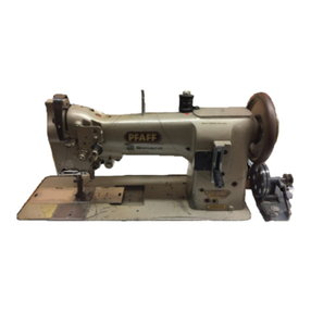
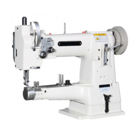
Pfaff 487 User manual

296-12-17 454
Justieranleitung engl. 06.99
Service manual
487

The reprinting, copying or translation of PFAFF instruction manuals, whether in whole or in
part, is only permitted with our previous consent and with written reference to the source.
G.M. PFAFF
Aktiengesellschaft
Postfach 3020
D-67653 Kaiserslautern
Königstr. 154
D-67655 Kaiserslautern
Editing/Illustrations
PFAFF
Dept. TES

Contents
Contents ...............................................................................Chapter - Page
1Safety......................................................................................................................... 1- 1
1.01 General notes on safety............................................................................................. 1-1
1.02 Safety symbols .......................................................................................................... 1 - 2
1.03 Danger warnings........................................................................................................ 1 - 2
2Adjustments .............................................................................................................. 2- 1
2.01 Notes on adjustment ................................................................................................. 2 - 1
2.02 Tools, gauges and other equipment........................................................................... 2 - 1
2.03 Abbreviations ............................................................................................................. 2 - 1
2.04 Explanation of symbols .............................................................................................. 2 - 1
2.05 Checking and adjusting aid ........................................................................................ 2 - 2
2.06 Preliminary adjustment of needle height ................................................................... 2 - 3
2.07 Needle in needle-hole centre ..................................................................................... 2 - 4
2.08 Neutral position of drop feed ..................................................................................... 2 - 5
2.09 Actuating lever under the reverse-feed control.......................................................... 2 - 7
2.10 Feeding motion of drop feed ..................................................................................... 2 - 8
2.11 Lifting motion of drop feed ........................................................................................ 2 - 9
2.12 Height of drop feed dog............................................................................................. 2 -10
2.13 Clearance between presser foot and needle plate..................................................... 2 - 11
2.14 Top feed actuating link............................................................................................... 2 -12
2.15 Neutral position of vibrating presser .......................................................................... 2 - 13
2.16 Vibrating presser clearance........................................................................................ 2 - 15
2.17 Lifting motion of vibrating presser ............................................................................. 2 - 16
2.18 Top feed lifting motion............................................................................................... 2 - 17
2.19 Position of lifting presser ........................................................................................... 2 - 18
2.20 Synchronizing the top feed ........................................................................................ 2 - 19
2.21 Stitch length alignment .............................................................................................. 2 -20
2.22 Eccentric hook shaft bearing...................................................................................... 2 -21
2.23 Final adjustment of needle rise, needle height, and bobbin case position finger ....... 2 - 22
2.24 Bobbin case opener height ........................................................................................ 2 - 23
2.25 Position of bobbin case opener.................................................................................. 2 - 24
2.26 Bobbin case opener motion ....................................................................................... 2 -25
2.27 Needle thread tension release ................................................................................... 2 -26
2.28 Thread check spring and thread regulator.................................................................. 2 -27
2.29 Bobbin winder............................................................................................................ 2 - 28
2.30 Knee lever resting position ........................................................................................ 2 - 29
2.31 Knee lever play........................................................................................................... 2 -30
2.32 Knee lever stroke limitation ....................................................................................... 2 - 31
2.33 Position of vibrating presser in relation to lifting presser ........................................... 2 - 32
2.34 Pressure of the vibrating- and lifting pressers............................................................ 2 -33
2.35 Stitch length limitation ............................................................................................... 2 - 34
Safety
1 Safety
1.01 General notes on safety
●The machine must only be operated by adequately trained operators and only when the
instruction manual has been fully read and understood!
●All notices on safety and the instruction manual of the motor manufacturer are to be
read before the machine is put into operation!
●All notes on the machine concerning danger and safety must be observed!
●The machine must be used for the purpose for which it is intended and must not be
operated without its safety devices; all regulations relevant to safety must be adhered
to.
●When part sets are changed (e.g. needle, presser foot, needle plate, feed dog or
bobbin), during threading, when the workplace is left unattended and during
maintenance work, the machine must be isolated from the power supply by turning off
the on/off switch or removing the plug from the mains!
●Daily maintenance work must only be carried out by appropriately trained persons!
●Repairs and special maintenance work must only be carried out by qualified technical
staff or persons with appropriate training!
●During maintenance or repairs on the pneumatic system the machine must be isolated
from the compressed air supply! The only exception to this is when adjustments or
function checks are carried out by appropriately trained technical staff!
●Work on the electrical equipment must only be carried out by technical staff who are
qualified to do so!
●Work on parts or equipment connected to the power supply is not permitted! The only
exceptions to this are specified in regulations EN 50110.
●Conversion or modification of the machine must only be carried out under observation of
all relevant safety regulations!
●Only spare parts which have been approved by us are to be used for repairs! We draw
special attention to the fact that spare parts and accessories not supplied by us have not
been subjected to testing nor approval by us. Fitting and/or use of any such parts may
cause negative changes to the design characteristics of the machine. We shall not ac-
cept any liability for damage caused by the use of non-original parts.
1 - 1

Safety
1.02 Safety symbols
Danger!
Special points to observe.
Danger of injury to operating or technical staff!
1.03 Danger warnings
Never put your hands in the sewing area during sewing!
Danger of injury by the needle!
While setting or adjusting the machine do not leave any objects on the
table nor in the needle plate area! Objects may be trapped or flung out of the
machine!
To adjust this mechanism the machine must be tilted backwards.
When setting the machine upright again, use both hands.
Danger of crushing between sewing head and table top!"
1 - 2

Adjustment
2 - 1
2 Adjustment
Before any servicing or adjustment work is carried out, the notes on safety in
this service manual and the safety notes in the instruction book have to be
observed!
Do not use a screw-clamp on the needle bar of the PFAFF 487, because this
will damage the special coating of the needle bar.
2.01 Notes on adjustment
All adjustments in this service manual refer to a fully assembled machine. Machine covers
which have to be removed for checking and adjustment work and refitted afterwards are not
mentioned in the text.
The screws or nuts indicated in brackets () are for fixation of parts of the machine and have
to be loosened before an adjustment and tightened again afterwards.
2.02 Tools, gauges and other equipment
●Set of screwdrivers with blade widths from 2 to 10 mm
●Set of open-ended spanners, 7 to 14 mm across-flats

●Set of allen keys, 1.5 to 6 mm
●Metal rule, part No. 08-880218-00
●Adjustment pin (5 mm dia.), part No. 13-030341-05
●Adjustment gauge, part. No. 61-111642-49
●Adjustment link, part No. 91-069375-15
●Adjustment foot, part No. 61-111639-20
2.03 Abbreviations
t.d.c. = top dead centre
b.d.c. = bottom dead centre
2.04 Explanation of symbols
Note, information
Service, repair,
adjustment, maintenance


2 - 2
Adjustment
●Turn the balance wheel until the needle bar is roughly in the required position.
●Insert the blocking pin in the required hole and press against it.
●Turn the balance wheel slightly back and forth so that the pin enters the cutout in the
bearing plate behind and thus blocks the machine.
Hole 1 ==
==
= 0.6 mm past top dead centre of the needle bar (0.6 past t.d.c.)
Hole 3 ==
==
= 0.6 mm past bottom dead centre of the needle bar (0.6 past b.d.c.)
Hole 4 ==
==
= 1.8 mm past bottom dead centre of the needle bar (needle rise position)
Hole 5 ==
==
= top dead centre of the needle bar (t.d.c.)
Hole 6 ==
==
= 4 mm past bottom dead centre of the needle bar (4 past b.d.c.)
2.05 Checking and adjusting aid
By blocking holes 1
to
6with a pin it is possible to accurately fix the required
needle bar positions.
15
346
Fig. 2 - 01

Adjustment
2 - 3
2.06 Preliminary adjustment of needle height
Requirement
With the needle bar at b.d.c. the underside of the needle bar must be at a distance of
approx. 16.5 mm from the needle plate.
Fig. 2 - 02
1
2
●Re-position needle bar 1(screws 2) according to Requirement.
16,5 mm

2 - 4
Adjustment
●Set the needle immediately above the needle hole.
●Loosen screws 1, 2
and 3.
●Reposition needle bar frame 4according to the Requirement
both crosswise and
lengthwise of the feeding direction.
●Tighten screw 3firmly and screw 2just a little.
●Turn screw 1to take up the guide pin behind it against the eye of the needle bar frame
and tighten it.
●Take out the needle.
●Loosen screw 2, turn the balance wheel a few turns (to remove any binding) and tighten
screw 2firmly.
Fig. 2 - 03
2.07 Needle in needle-hole centre
Requirement
The needle must enter exactly in the centre of the needle hole.
1
4
2
3

Adjustment
2 - 5
●Set feed regulator lever 1in its lowest position.
●Turn bush 2(screw 3) so that mark 4is facing downwards and the edge of the milled
surface is at an angle of approx. 45° to the front side of the machine.
●(For the final adjustment, see Chapter 2.20 "Top feed synchronization".)
●Insert a suitable pin or allen key in hole 5of tensioning ring 6and hold shaft 7with it
firmly.
●Turn shaft 7
(screw 8) according to Requirement.
2.08 Neutral position of drop feed
2.08.01 Adjustment with the gearcase closed
Requirement
At stitch length setting "O" the drop feed must not make any feeding movement when the
balance wheel is turned.
Fig. 2 - 04
56
8
7
45°
23
4
1

2 - 6
Adjustment
●Set feed regulator lever 1in its lowest position.
●Turn bush 2(screw 3) so that mark 4is facing downwards and the edge of the milled
surface is at an angle of approx. 45° to the front side of the machine.
(For the final adjustment, see Chapter 2.20 "Top feed synchronization".)
●Turn crank 5(screw 6) according to Requirement.
Fig. 2 - 05
56
2.08.02 Adjustment with the gearcase opened
45°
23
4
1

Adjustment
2 - 7
●Loosen screws 1and 2.
●Make sure that reverse-feed control lever 3is resting on stop 4, move actuating lever 5
lightly against the reverse-feed control and tighten screw 1again.
Leave screw 2loose until the top-feed neutral position is adjusted
(Chapter 2.15).
2.09 Actuating lever under the reverse-feed control
Requirement
At the longest stitch length setting, reverse-feed control lever 3must have a slight play
(approx. 0.3 mm)
when pressed lightly.
Fig. 2 - 06
1
2
3
5
4

2 - 8
Adjustment
●Turn feed eccentric 1(screws 2) according to Requirement. Make sure that the cutout
in the feed eccentric is visible.
2.10 Feeding motion of drop feed
Requirement
At the longest stitch length setting and with the needle bar in position 0.6 past t.d.c.
(blocking hole 1) the feed dog must not move when the reverse-feed control is operated.
Fig. 2 - 07
2
1
1

Adjustment
2 - 9
●Turn lifting eccentric 1(screws 2) according to Requirement.
Make sure that there is slight play between lifting eccentric 1and the crank
lever behind it.
Fig. 2 - 08
2.11 Lifting motion of drop feed
Requirement
At stitch length setting "0" and with the needle bar in position 0.6 past t.d.c. (blocking hole
1) the feed dog must be at t.d.c.
The cutout in lifting eccentric 1must face roughly vertically downwards.
1
2
1

2 - 10
Adjustment
●Reposition feed bar 1(screws 2) according to Requirement 1.
●Lower presser foot onto gauge.
●Turn eccentric 3(screws 4) and eccentric 5(screws 6) according to Requirement 2.
2.12 Height of drop feed dog
Requirement
At stitch length setting "0" and with the needle bar in position 0.6 mm past t.d.c.
(blocking hole 1) the feed dog must:
1. be centred in the feed slots of the needle plate both crosswise and lengthwise,
2. be at top dead centre and resting against the adjustment gauge throughout its length.
Fig. 2 - 09
3
4
5
6
2
11

Adjustment
2 - 11
12
11
7
6
2
1
3
13
2.13 Clearance between presser foot and needle plate
Requirement
When lifting lever 1is raised there must be a clearance of 5 mm between the presser foot
and the needle plate.
●Lower presser foot onto needle plate using lifting lever 1.
●Reduce pressure on the presser bar by unscrewing regulating screw 2(knurled nut 3).
●Loosen screw 4, push pin 5out and swing link 6out of the fork of lever 7.
●Set lever 8at its outermost position by turning the balance wheel.
●Place the feed-dog adjustment gauge, cutout facing downwards, under the presser foot.
●Loosen screw 10
and push pin
11 out.
●Loosen screw 12.
●Position the presser foot crosswise so that its edge is parallel with the needle plate
cutout
●Move lifting piece 13 fully down and tighten screw 12.
Leave screws 4and 10 loose for the next adjustment.
Fig. 2 - 10
86
7
4
7
11
10
5

2 - 12
Adjustment
Fig. 2 - 11
●Lower the presser foot using lifting lever 1.
●Loosen screw 2.
●Swing link 3
into the fork of lever 4, insert pin 5and tighten screw 6(check for free
movement and set lever 4if necessary).
●Set stitch length at "0".
●Position vibrating presser at centre of lifting presser cutout and tighten screw 2.
●Loosen screw 7.
●Align the hole in lever 8with the elongated hole of lever 9,,
,,
, without any lateral play, if
necessary re-position or set lever 8.
●Insert pin 10 with its eccentric lobe facing downwards into the holes of levers 9and 8
and tighten screw 11.
●Move lever 12 to its outermost position.
●Push lever 8in feeding direction until you feel it move into contact, and tighten screw 7.
●Position the vibrating presser crosswise so that it does not touch the lifting presser
(screw 13).
8
9
11
4
6
7
2
1
10
13
2.14 Top feed actuating link
Requirement
1. All moving parts of the top feed must move freely but without any play.
2. The vibrating presser must not contact the lifting presser.
12
3
4
5

Adjustment
2 - 13
2.15 Neutral position of top feed
Requirement
With the stitch length and top feed set at "0" and with adjustment link 99
99
9 fitted, drive lever 22
22
2
must not make any movement when the balance wheel is turned.
1
910 2
54
17
18
●Raise the presser foot.
●Loosen screws 1, 2 and 3.
●Set crank 4parallel with crank 5and tighten screw 2.
Fig. 2 - 12
14
13
16
22
8
7
6
21 20
19 3
Other manuals for 487
4
Table of contents
Other Pfaff Sewing Machine manuals

Pfaff
Pfaff 138 User manual

Pfaff
Pfaff 141 User manual

Pfaff
Pfaff 3307-1 SERIES User manual

Pfaff
Pfaff 421E1 User manual

Pfaff
Pfaff creative 1.5 User manual

Pfaff
Pfaff Creative 7550 User manual

Pfaff
Pfaff QUILT EXPRESSION 4 User manual

Pfaff
Pfaff 3588-04/020 User manual

Pfaff
Pfaff hobby 4240 User manual

Pfaff
Pfaff 1181 User manual