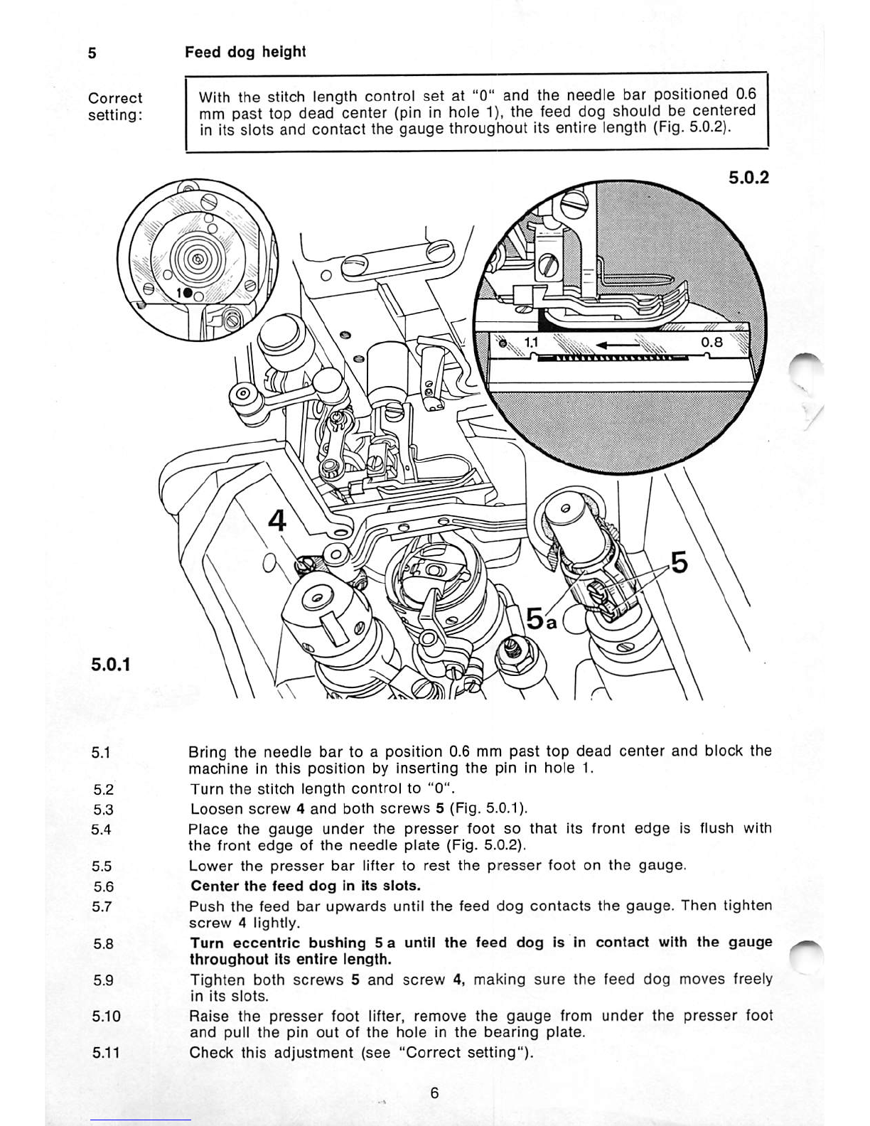
Pfaff 487 User manual

Service
Manual
PFAFF
INDUSTRIEMASCHINEN
GMBH
KAISERSLAUTERN
From the library of: Superior Sewing Machine & Supply LLC

Instructions
for
adjusting
the
Pfaff 487
Important
note
Never use a C-clamp on the needle bar of Pfaff 480
series
machines
because
this
would
damage
its
special
coating.
On machines which
are
put into operation for the first time or which have been idle
for a longer period of time
(1
or 2 months) make absolutely sure to check the hook
lubrication
system
(Section
14).
Important
note
for
version
N
machines
All
adjustments described In this book also apply to version N machines (6.0 mm maximum ~ -
stitch length). An exception
are
machines supplied earlier whose stitch length control Is
knurled
all
the
way
around.
If
on
these
machines
the
reverse-feed
control
can
be
moved
when
the
stitch
length
control
Is
set
at "0", all adjustments which are carried out with the stitch length
set
at "0" must
be
made
with
the
reverse-feed
control
depressed.
If on machines having a stitch length control which Is knurled all the way around the
reverse-feed control
cannot
be moved, all
adjustments
which have to be
carried
out
with
the stitch length
set
at "0" must be
made
with the stitch length
set
at "1.5" and the
reverse-feed
control
depressed.
Tools,
gauges
and
other
equipment
needed
for
adjusting
the
Pfaff 487:
1
set
of
screwdrivers
with
blades
from
2
to
10
mm
wide
1
set
of
spanners
from
7
to
14 mm
wide
1
22-mm
spanner
1
set
of
alien
keys
ranging
from
1.5
to 6.0 mm
1
metal
rule
1
adjusting
pin, 5 mm dia.. No. 13-030 341-05
1
gauge.
No. 61-111
642-19
(gauge
foot
No. 61-111 639-20)
1
wrapper
with
System
134
needles
1
strip
of
white
paper,
sewing
thread
and
material
for
testing
purposes.
From the library of: Superior Sewing Machine & Supply LLC

1
1.1
Note:
Preparations
for
adjustment
Take
out
both
screws
of
the
face
cover
and
remove
the
cover.
The rnachlne can be blocked with the needle bar at different positions by
inserting a pin in one of the five holes of the bearing plate (Fig.
1.0.1).
After positioning the needie bar, push the pin into the appropriate hole
untii it enters the recess behind the bearing plate, thus blocking the
machine.
The
function
of
each
of
the
five
holes
is
as
follows:
Hole
1 (0.6 n.o.T.) = 0.6 mm
past
the
top
of
the
needle
bar
stroke.
This
hole
is
used
for
timing
the
feed
eccentrics
and
adjusting
the
feed
dog
height.
Hole
2(o.T.F.) =
top
of
take-up
lever
stroke.
(On
subcl.
-900
machines,
this
hole
Is
used
for
timing
the
synchronizer.)
Hole
3 (0.6 n.u.T.) = 0.6 mm
past
the
bottom
of
the
needle
bar
stroke.
(This
hole
is
needed
on
Pfaff 481
and
485
machines.)
Hole
4(Schl-H 1.8) =
1.8
mm
past
the
bottom
of
the
needle
bar
stroke.
This
hole
serves
to
time
the
sewing
hook
and
the
bobbin
case
opener.
Hole
5(o.T.N.) =
top
of
needle
bar
stroke.
1
From the library of: Superior Sewing Machine & Supply LLC

Correct
setting:
Note:
2.1
2.2
2.3
2.4
2.4.1
2.4.2
2.4.3
2.4.4
2.4.5
2.4.6
2.4.7
2.4.8
Zeroing
the
bottom
feed
motion
With the stitch length
set
at "0", the feed dog must not move when the
balance
wheel
Is
turned.
The
bottom
feed
motion
can
also
be
zeroed
with
the
gearcase
closed
(see
Fig. 2.0.2).
1
Remove
the
needle
from
the
needle
holder.
Raise
the
presser
bar
lifter.
Remove
the
knee
lever
together
with Its
joint
and
tilt
the
machine
back.
Adjustment
procedure
to
be
applied
when
the
gearcase
Is
open.
Turn
the
stitch
length
control
to
"0".
Take
out
the
16
screws
of
the
gearcase
cover
and
remove
the
cover
with Its
gasket,
making
sure
that
the
oil, If any, Is
drained
off into a container.
Take
the
oil
sponge
out
of
the
gearcase.
Loosen
screw
2 of
feed
crank
1
just
sufficiently to allow
the
crank
to
be
turned
on
Its
shaft
against
resistance.
To
facilitate
adjustment.
Insert
a
screwdriver
In
the
slot
of
feed
rock
shaft
crank
3.
Rotate
the
balance
wheel
and
at
the
same
time
adjust
feed
crank
1
on
its
shaft
until
the
feed
dog
(or
rather
the
screwdriver
in
feed
rock
shaft
crank
3) no
longer
moves.
In
this
position,
tighten
screw
2 of
feed
crank
1.
Check
this
adjustment
(see
"Correct
setting").
From the library of: Superior Sewing Machine & Supply LLC

2.5
Adjustment
procedure
to
be
applied
when
the
gearcase
cover
Is
closed.
2.0.2
2.5.1
Turn
the
stitch
length
control
to
"0".
2.5.2
Loosen
screw
6 of
the
feed
regulator
crank.
2.5.3 To
facilitate
adjustment,
Insert
a
screwdriver
In
the
slot
of
feed
rock
shaft
crank
3 (Fig. 2.0.1).
2.5.4 With
the
aid
of a
spanner
pushed
over
hexagon
tension
nut
4
turn
feed
regulator
shaft
5
until
the
feed
dog
(or
rather
the
screwdriver
In
the
feed
rock
shaft
crank)
remains
absolutely
still
when
the
balance
wheel
Is
turned.
2.5.5 In
this
position,
hold
the
feed
regulator
shaft
fast
with
the
spanner
and
tighten
screw
6.
2.5.6
Check
this
adjustment
(see
"Correct
setting").
3
From the library of: Superior Sewing Machine & Supply LLC

Bottom
feed
driving
motion
Correct
With
the
machine
set
for its
longest
stitch
and
the
needle
bar
positioned
setting: 0.6
mm
past top dead center
(pin
in hole 1), the feed dog should not
move
when
the
reverse-feed
control
is
operated.
m
3.1
Loosen
both
screws
2 in
feed
driving
eccentric
1.
3.2 Bring
the
needle
bar
to a position 0.6 mm
past
top
dead
center
and
block
the
machine
in
this
position
by
inserting
the
pin in
hole
1.
3.3
Set
the
machine
for
its
longest
stitch.
3.4 To facilitate
adjustment,
insert
the
screwdriver
in
the
slot
of feed rock
shaft
crank
3.
3.5 Move
the
reverse-feed
control
up
and
down
and
simultaneously
turn
feed
driving
eccentric
1until its
notch
Is
visible
and
the
feed
dog
(or
rather
the
screwdriver
in
feed
rock
shaft
crank
3) is
compieteiy
motionless.
3.6 In this position, tighten
the
accessible
screw
2 in
feed
driving
eccentric
1.
3.7 Pull
the
pin
out
of
the
hole in
the
bearing
plate
and
tighten
the
second
screw
2 in
feed
driving
eccentric
1.
3.8
Check
this
adjustment
(see
"Correct
setting").
3.9
Pull
the
screwdriver
out
of
the
slot
in
feed
rock
shaft
crank
3.
From the library of: Superior Sewing Machine & Supply LLC

Correct
setting:
Bottom
feed
lifting motion
With the stitch length control
set
at "0" and the needle bar positioned
0.6 mm
past
top
dead
center
(pin hole 1), the feed dog should
be
at Its
highest point. The notch in feed lifting
eccentric
1should then be positioned
perpendicularly
below
the
center
of
the
shaft
(Fig. 4.0.2).
4.0.2
4.1
Turn
the
stitch
length
control
to "0"
and
remove
the
bedplate
cover.
4.2
Loosen
both
screws
2 In
feed
lifting
eccentric
1 (Fig. 4.0.1).
4.3 Bring
the
needle
bar
to a
position
0.6 mm
past
top
dead
center
and
block
the
machine
in
this
position
by
inserting
the
pin in
hole
1.
4.4 Turn feed lifting
eccentric
1 until the feed dog is at its highest point
and
the
notch in
feed
lifting
eccentric
1 is
positioned
perpendicularly
below
the
center
of
the
shaft
(Fig. 4.0.2).
4.5 In this position, tighten
the
accessible
screw
2, making
sure
there
is a smali
amount
of play
between
feed
lifting
eccentric
1
and
the
bearing.
4.6 Pull
the
pin
out
of
the
hole in
the
bearing
plate
and
tighten
the
second
screw
2
too.
4.7 Check this
adjustment
(see
"Correct
setting").
From the library of: Superior Sewing Machine & Supply LLC

Feed
dog
height
With the stitch length control
set
at "0" and the needle bar positioned 0.6
mm past lop dead center (pin in hole 1), the feed dog should be centered
in its slots and
contact
the
gauge
throughout its entire length (Fig. 5.0.2).
Bring the needle bar to a position 0.6 mm
past
top
dead
center
and block the
machine
in
this
position
by
inserting
the
pin in
hole
1.
Turn
the
stitch
length
control
to
"0".
Loosen
screw
4
and
both
screws
5(Fig. 5.0.1).
Place
the
gauge
under
the
presser
foot
so
that
its
front
edge
is
flush
with
the
front
edge
of
the
needle
plate
(Fig.
5.0.2).
Lower
the
presser
bar
lifter
to
rest
the
presser
foot
on
the
gauge.
Center
the
feed
dog
In
its
slots.
Push
the
feed
bar
upwards
until
the
feed
dog
contacts
the
gauge.
Then
tighten
screw
4
lightly.
Turn
eccentric
bushing
5 a until
the
feed
dog
Is In
contact
with
the
gauge
throughout
Its
entire
length.
Tighten
both
screws
5
and
screw
4,
making
sure
the
feed
dog
moves
freely
in
its
slots.
Raise
the
presser
foot lifter,
remove
the
gauge
from
under
the
presser
foot
and
pull
the
pin
out
of
the
hole
in
the
bearing
plate.
Check
this
adjustment
(see
"Correct
setting").
From the library of: Superior Sewing Machine & Supply LLC

6
Centering
the
needle
In
the
needle
hole
Correct
A
straight
needle
should
be
positioned
exactly
In
the
middle of
the
needle
setting:
hole
(Fig. 6.0.2).
i
i8i
Bring
the
needle
bar
to its
highest
point
and
remove
the
presser
foot.
Insert
a
new
needle
(system
134 kk) into
the
needle
bar.
Take
out
screw
6 in
the
eye
of
the
needle
bar
frame
(Fig.
6.0.1).
Loosen
screw
7
of
the
eccentric
stud.
Loosen
screw
8 of
the
needle
bar
frame
hinge
stud.
Turn
the
balance
wheel
while
moving
the
needle
bar
frame
sideways,
and
turn
the
eccentric
stud
until
the
needle
is
centered
In
the
needle
hole
(Fig. 6.0.2).
In
this
position,
tighten
screw
8.
Pull
out
the
eccentric
stud
until
it
contacts
the
needle
bar
frame
and
tighten
screw
7.
Replace
screw
6
with
its
washer
on
the
eccentric
stud
and
tighten
the
screw.
Loosen
screw
7
again
and
turn
the
balance
wheel
a
few
turns
to
ensure
that
the
needle
bar
frame
is
not
under
stress.
Then
tighten
screw
7
securely
again.
Check
this
adjustment
(see
"Correct
setting").
From the library of: Superior Sewing Machine & Supply LLC

Correct
setting:
7.0.1
7.1
7.2
7.3
7.4
7.5
7.6
7.7
7.8
7.9
7.10
7.11
7.12
7.13
Eccentric
hook
shaft
bearing
There
should
be
a
clearance
of 0.4 mm
between
hook
point
and
the
middle
of
the
clearance
cut
of
the
needle
when the sewing hook is up
against
oil
distributor
ring 3 (Fig. 7.0.2). Also
there
should
be
aminimum
amount
of
play
between
the
gears.
-Q
rmirn
m
Remove
the
needle
plate
and
the
feed
dog.
Loose
screw
1 of oil
regulating
valve
2
and
swivel
the
oil
tube
out
of oil
distributor
ring 3.
Loosen
screw
4
on
the
surface
of
the
bedplate
(Fig. 7.0.2).
Turn
eccentric
hook
shaft
bearing
5
so
that
the
recess
Is
visible
from
below
(see
arrow
In
Fig.
7.0.1)
and
the
two
spur
gears
have
neither
too
much
play
nor
stand
too
close
together.
Loosen
both
screws
6 of
the
sewing
hook.
Push
the
sewing
hook
up
against
oil
distributor
ring 3.
Turn
the
sewing
hook
and
reposition
the
needle
bar
until
the
hook
point
is
positioned
in
the
middle
of
the
clearance
cut
of
the
needle.
Reposition
hook
shaft
bearing
5
until
there
Is a
clearance
of 0.4
mm
betw
een
hook
point
and
the
middle
of
the
clearance
cut
of
the
needle,
making
sure
however
that
the
bearing
Is
not
turned
and
that
the
hook
remains
In
contact
with
oil
distributor
ring
3.
In
this
position,
securely
tighten
screw
4.
Loosen
both
screws
8.
Reposition
gear
7 on its
shaft
until it is
exactly
in line with
the
small
gear.
Tighten
both
screws
8
securely,
making
sure
that
the
second
screw
of
spur
gear
7 —
as
seen
in its
direction
of
rotation
— is
positioned
in
the
groove
of
the
shaft
and
both
gears
have
enough
play.
Do
not
tighten
screws
6
as
yet
and
leave
the
oil
tube
swivelled
away
for
the
following
adjustment.
8
From the library of: Superior Sewing Machine & Supply LLC

Correct
setting:
Needle
bar
height,
hook
timing
and
hook-to-needie
clearance
When
the needle bar is positioned 1.8
mm
past
bottom
dead center
(pin
in hole 4), the top edge of the needle eye should be positioned 0.8
mm
below the bottom edge of the hook point
(Fig.
8.0.3).
In this position, there
should be a clearance of
0.1
mm
between hook point and needle
(Fig.
8.0.2).
s
oo
o
8.0.2
8.1 Bring the needle
bar
to a point 1.8 mm
past
bottom
dead
center, making
sure
that
the
needle
does
not
strike
the
sewing
hook. Block
the
machine
In
this
position
by
inserting
the
pin in
hole
4.
8.2 Loosen both
screws
1 in
the
needle
bar
connection
stud
(Fig. 8.0.1).
8.3 Turn
the
sewing hook on its ^haft until its point is exactly opposite
the
center
line
of
the
needle.
8.4 Move
the
needle
bar
up
or
down
until
there
Is a
clearance
of 0.8 mm
between
the
top
edge
of
the
needle
eye
and
the
bottom
edge
of the sewing hook
(Fig. 8.0.3).
8.5 In
this
position,
tighten
both
screws
1, making
sure
that
the
needle
bar
is not
turned
(Fig. 8.0.1).
8.6
Adjust
the
sewing
hook
laterally
until
there
is a
clearance
of 0.1 mm
between
its point
and
the
needle
(center
of scarf), making
sure
the
hook point Is op
posite
the
center
line of
the
needle
and
the
position finger Is In
the
slot
of
the
bobbin
case.
8.7 In
this
position,
tighten
the
accessible
screw
2.
'8.8
Pull the pin out of the hole in the bearing plate and tighten the second
screw
2.
8.9
Check
this
adjustment
(see
"Correct
setting").
9
From the library of: Superior Sewing Machine & Supply LLC

Correct
setting:
9.1
9.2
9.3
9.4
9.5
Eccentric
bobbin
case
opener
shaft
bushing
When at Its left point of reversal, bobbin
case
opener finger 3 should be
positioned vertically so that it Is exactly opposite the lug of bobbin case
base
4 (Fig. 9.0.2).
9.0.1
Loosen
screw
1 of
eccentric
bobbin
case
opener
shaft
bushing
2 (Fig. 9.0.1).
Turn
the
balance
wheel to bring
the
opener
finger to Its left point of reversal.
Turn bushing 2 until
opener
finger 3 is exactly opposite
the
lug of bobbin
case
base
4. (Fig. 9.0.2). Make
sure
the bobbin
case
can
be easily removed
from
the
sewing
hook.
In
this
position,
tighten
screw
1.
Check
this
adjustment
(see
"Correct
setting").
10
From the library of: Superior Sewing Machine & Supply LLC

10
Correct
setting:
10.1
10.2
10.3
10.4
10.5
10.6
10.7
10.8
10.9
Position of
bobbin
case
opener
There
should
be a clearance of abt. 0.8
mm
between
bobbin
case opener
finger 1 and
bobbin
case base 5
(Fig.
10.0.2).
When
opener finger 1 is on
the
left of its stroke,
there
should be a
clearance
of abt. 0.3 mm between
bobbin case base 5 and position finger 6
(Fig.
10.0.3),
In this position, the
lug on collar4 should be up against the stop ofopenerfinger1
(Fig.
10.0.1).
10.0.1
0.3
mm
10.0.2
10.0.3
Loosen
screw
3
of
collar
4.
Loosen
clamp
screw
2 of
opener
finger 1
just
sufficiently to allow it to be
turned
on
its
shaft
against
resistance.
Reposition
opener
finger
1
on
its
shaft
untii
there
is
a
clearance
of
0.8
mm
between
it
and
bobbin
case
base
5 (Fig. 10.0.2).
Rotate
the
balance
wheel
until
opener
finger
1 is
on
the
left of its
stroke.
Turn
opener
finger
1untii
there
is a
thread
ciearance
of 0.3 mm
between
position
finger
6
and
the
right
waii
of
the
position
slot
in
the
bobbin
case
base
when
opener
finger 1
contacts
the
iug of
bobbin
case
base
5 (Fig. 10.0.3).
In
this
position,
securely
tighten
screw
2.
Push
collar 4 up
against
opener
finger 1
and
turn it
so
that its iug is up
against
the
stop
of
opener
finger
1.
In
this
position,
tighten
screw
3.
Check
this
adjustment
(see
"Correct
setting").
11
From the library of: Superior Sewing Machine & Supply LLC

Timing
Ihe
bobbin
case
opener
When the needle bar is positioned 1.8 mm past bottom dead center (pin
in hole 4), opener finger 3 should be at its right point of reversal (Fig.
11.0.2).
11.0.1
.s
h"! lA'-
. V
11.0.2
Loosen
booth
screws
2 (Fig. 11.0.1).
Bring the needle bar to a point 1.8 mm past bottom
dead
center
and block
the
machine
in
this
position
by
inserting
the
pin in
hole
4.
To
facilitate
determining
the
exact
point
of
reversal
insert
a
small
screw
driver
in
the
slot
of
the
clamp
of
opener
finger
3.
Turn
opener
eccentric
1 until
opener
finger 3 Is at Its right point of reversal
(Fig. 11.0.2).
in this position, tighten the
accessible
screw
2 of
opener
eccentric
1 (Fig.
11.0.1), making
sure
there is sufficient play between
opener
eccentric
1 and
the
lifting
eccentric.
Puii the pin out of the hole In the bearing plate and tighten the
second
screw
2
also.
Pull
the
screwdriver
out
of
the
clamp
slot
and
check
this
adjustment
(see
"Correct
setting").
From the library of: Superior Sewing Machine & Supply LLC

12
Correct
setting;
12.1
Note:
12.2
Oil
tube
In oil
distributor
ring
Oil
tube
1should be positioned In the hole of oil distributor ring 2 (Fig.
12.0.2).
12.0.2
gnnr
12.0.1
Insert
oil
tube
1 Into
the
hole
of oil distributor ring 2
(see
arrow
In Fig.
12.0.2); If
necessary,
turn oil distributor ring 2 accordingly.
On
subcl.
-900
machines
the
oil
distributor
ring
cannot
be
turned
until you
have
loosened
the
three
screws
on
the
front
side
of
the
hook
shaft
bearing.
Tighten
screw
3 of oil regulating valve 4 (Fig. 12.0.1).
13
From the library of: Superior Sewing Machine & Supply LLC

13
Correct
setting;
Oil
check
valve
There
should
be
a
clearance
of 1.0 mm
between
actuating
rod
3 of
the
centrifugal governor and push rod 4 of the oil check valve (Fig. 13.0.2).
13.0.2
13.0.1
13.1
Loosen
screw
1 of oil
check
valve
2 (Fig. 13.0.1).
13.2
Push
actuating
rod 3 Into
the
centrifugal
governor.
13.3
Press
push
rod 4 Into oil check valve 2 until a
noticeable
resistance
Is felt.
13.4
Reposition
oil
check
valve 2 until
there
Is a
clearance
of 1.0 mm
between
actuating
rod
3
and
push
rod
4(Fig. 13.0.2).
13.5 In
this
position,
tighten
screw
1.
13.6
Check
this
adjustment
(see
"Correct
setting").
13.7
Soak
the
oil
sponge
with oil
and
replace
It In
the
gearcase
so
that
Its
large
recess
is
at
the
bottom
left
and
the
oil
tube
is
placed
on
top
of It.
13.8
Clean
the
gasket
face
on
the
gearcase
and
the
gasket
of
the
gearcase
cover.
13.9
Replace
the
gearcase
cover
and
simultaneously
screw
on
the
two machine
legs,
tightening
the
screws
of
the
cover
crosswise.
14
From the library of: Superior Sewing Machine & Supply LLC

14
Correct
setting:
Hook
lubrication
After
the
machine
has
run at full
speed
for
about
ten
seconds,
a fine
trace
of oil should
appear
on a piece of
paper
placed over the needle plate
cutout
above
the
hook
raceway.
14
14.1
Check
the
oil level
and,
if
necessary,
top
up
the
reservoir
until
the
oil level
is in
line
with
the
upper
mark.
Use
oil No.
280-1-120144.
14.2
Turn
in
regulating
screw
1 of oil
regulating
valve 2
as
far
as
it will go,
and
then
back
about
three
turns.
14.3
Start
the
machine
and
run it until
the
sewing
hook
starts
emitting
oil.
14.4
Turn
regulating
screw
1 in
completely
and
then
out
half
a
turn.
14.5
Let
the
machine
run
about
1
minute.
14.6
Place
a
piece
of
white
paper
over
the
needle
plate
cutout.
14.7
Let
the
machine
run
about
ten
seconds.
Then
check
to
see
if a
fine
trace
of
oil
has
appeared
on
the
paper
opposite
the
hook
raceway.
14.8 If
too
much
oil Is
emitted,
turn
regulating
screw
1 in a
little;
or
If
too
little oil
Is
emitted,
turn
It
out
somewhat.
14.9
Check
this
adjustment
(see
"Correct
setting").
15
From the library of: Superior Sewing Machine & Supply LLC

15
Correct
setting:
15.1
15.2
15.3
15.4
15.5
(S)
Zeroing
the
top
feed
motion
To
determine
whether
the
following
setting
Is
correct,
adjustments
15.1 to
15.5
must
be
carried
out
first.
With
the
stitch
length
set
at
"0",
feed
driving
lever
7 (Fig. 15.0.4)
must
not
move
when
the
balance
wheel
Is
turned.
i
lllil
15.0.1
Turn
regulating
screw
1
out
a
few
turns.
Turn
out
stop
screw
2until a
resistance
Is felt.
Q
o
Set
the
machine
for
Its
longest
stitch
and
move
the
reverse-feed
control
to
Its
upper
position.
Turn
in
regulating
screw
1until
the
reverse-feed
control
begins
to
move
downwards.
Turn
regulating
screw
1
back
half
a
turn.
16
From the library of: Superior Sewing Machine & Supply LLC

Not©:
For information on version N machines supplied earlier
see
inside front cover.
15.6
15.7
15.8
15.9
15.10
15.11
15.12
15.13
15.0.2
m/
liiiiii
15.0.3 15.0.4
Turn
the
stitch
length
control
to "0"
and
loosen
screw
3.
Adjust
scale
4
so
that
the
zero
mark
is
positioned
above
the
tip of
the
pointer.
Retain
the
scaie
in
this
position
and
tighten
screw
3.
Repiace
and
screw
on
the
belt
guard
and
the
rear
arm
cover.
Loosen
screw.
5.
Adjust
crank
6
so
that
feed
driving
lever
7
does
not
move
when
the
balance
wheel
Is
turned.
In
this
position
tighten
screw
5.
Check
this
adjustment
(see
"Correct
setting").
17
From the library of: Superior Sewing Machine & Supply LLC

With
the presser bar lifter raised, there should be a clearance of 7.0 mm
between
presser
foot and needle plate (Fig. 16.0.2).
From the library of: Superior Sewing Machine & Supply LLC
Other manuals for 487
4
Table of contents
Other Pfaff Sewing Machine manuals

Pfaff
Pfaff 1245 User manual

Pfaff
Pfaff 1445 User manual

Pfaff
Pfaff hobbylock 2.0 User manual

Pfaff
Pfaff Creative Vision User manual

Pfaff
Pfaff 1183-712/02 Guide

Pfaff
Pfaff hobbylock 4764 User manual

Pfaff
Pfaff hobby GrandQuilter 1200 User manual

Pfaff
Pfaff 1295 User manual

Pfaff
Pfaff 3519-4/01 User manual

Pfaff
Pfaff hobbylock 4762 User manual
Popular Sewing Machine manuals by other brands

Baby Lock
Baby Lock Tiara Features and specifications

Hohner
Hohner ORION 4 operating instructions

UnionSpecial
UnionSpecial 80800R INSTRUCTIONS, ENGINEER'S AND ILLUSTRATED PARTS MANUAL

JUKI
JUKI LBH-1790 Series instruction manual

Baby Lock
Baby Lock Solaris 2 Instruction and reference guide

JUKI
JUKI IP-100 instruction manual