Pfeuffer Milomat User manual

Translation
If the system is being supplied or subsequently sold to countries of the EEA, the Operating Instructions must be
translated into the language of the country of use accordingly. If there are any discrepancies with the translated
text, then use the original Operating Instructions (German version) or contact the manufacturer.
Operating Instructions in electronic format
PDFs of the original Operating Instructions (German version) and translations of the original Operating Instructions
can be requested by e-mail. Ensure the correct type designation and serial number is stated!
© Copyright
The passing on or reproduction of this document, and use and disclosure of its contents are prohibited unless
expressly permitted. We will claim compensation for damages. All rights reserved with regard to the granting of
patents, utility models or designs.
(DIN ISO 16016)
2 | 30
Operating instructions Milomat | Revision 1.2
These Operating Instructions are a constituent part of the MILOMAT laboratory mill and must be
available to all operating personnel at all times. They are intended for the operating company of the
system, the operating personnel and the specialists who are responsible for the transport, assembly,
installation, operation, maintenance, cleaning, disassembly and disposal.
The Pfeuffer GmbH has prepared and reviewed these Operating Instructions with the greatest care.
However, no guarantee is made for its completeness or accuracy.
Subject to technical modifications.

Table of contents
Revision 1.2 | Operating instructions Milomat
3 | 30
1 Introduction ............................................................................................................................... 4
1.1 Intendend use ....................................................................................................................................................... 4
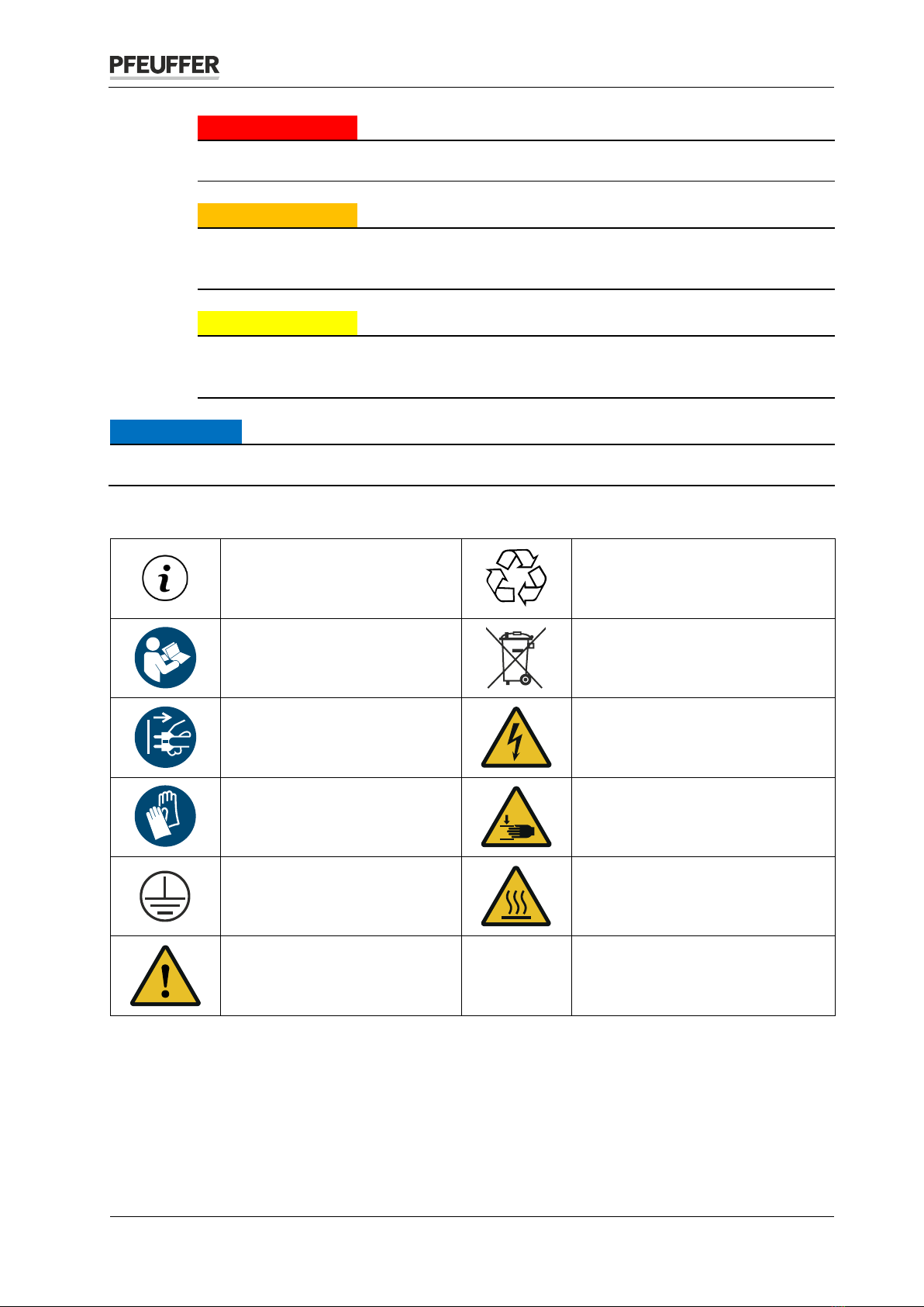
1.2 Design characteristics of hazard warnings ............................................................................................................ 4
1.3 Pictograms in the Operating Instructions ............................................................................................................. 5
1.4 Designation ........................................................................................................................................................... 5
1.5 Declaration of conformity ..................................................................................................................................... 6
2 Safety......................................................................................................................................... 7
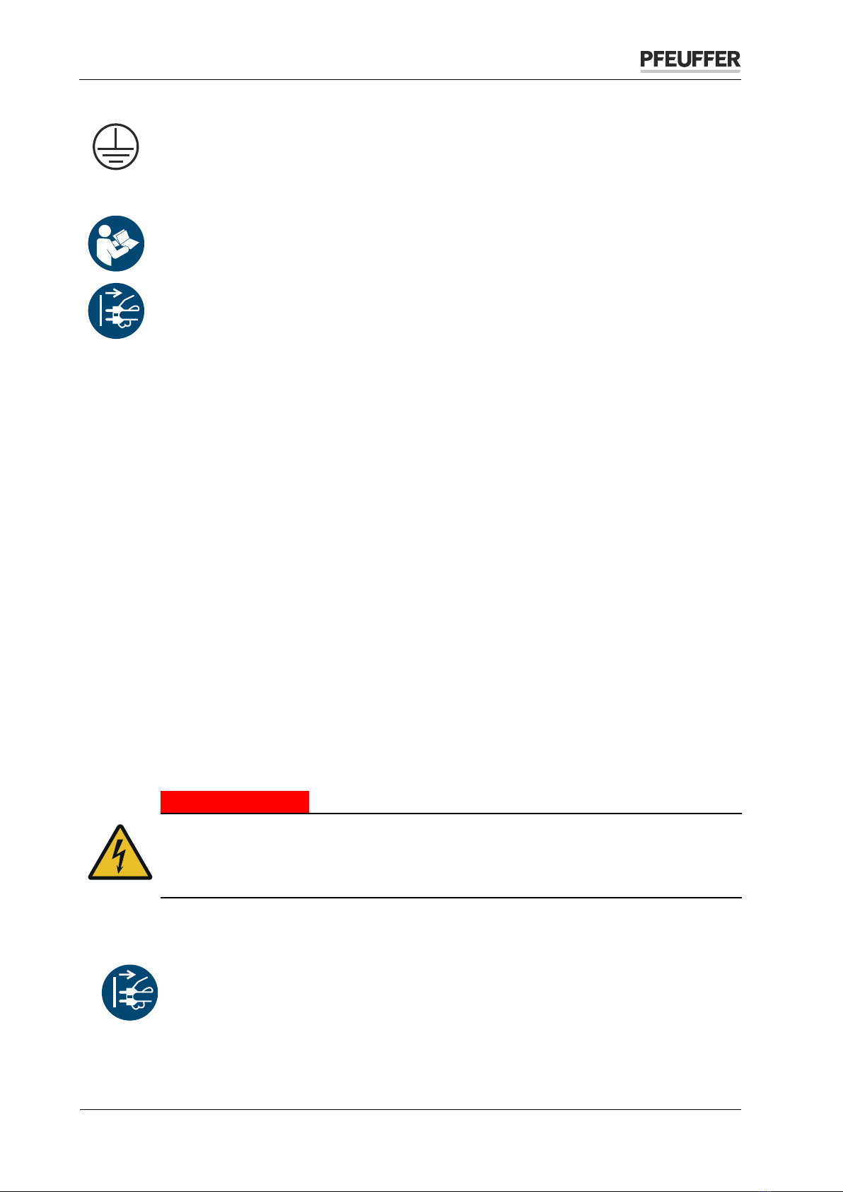
2.1 Installed safety systems ........................................................................................................................................ 7
2.1.1 Mains disconnector in a portable device..................................................................................................... 7
2.1.2 Protective covers ......................................................................................................................................... 7
2.1.3 Safety switch................................................................................................................................................ 8
2.2 Operating and danger areas.................................................................................................................................. 8
2.3 Operating and maintenance personnel ................................................................................................................ 8
2.4 Safety measures (to be carried out by the owner) ............................................................................................... 9
2.5 General safety notes ........................................................................................................................................... 10
2.6 Safety tests.......................................................................................................................................................... 10
2.7 Residual dangers in connection with the MILOMAT........................................................................................... 10
2.8 Switch-off procedure .......................................................................................................................................... 10
3 Technical data .......................................................................................................................... 11
3.1 Dimensions and weight....................................................................................................................................... 11
3.2 Power supply....................................................................................................................................................... 11
3.3 General data........................................................................................................................................................ 11
4 Delivery, transport and storage................................................................................................. 11
4.1 Scope of delivery ................................................................................................................................................. 11
4.2 Transport and packaging..................................................................................................................................... 11
4.3 Intermediate storage .......................................................................................................................................... 12
4.4 Transport to the installation site (by the customer) ........................................................................................... 12
5 Installation and commissioning ................................................................................................. 12
6 Function ................................................................................................................................... 13
6.1 Overview ............................................................................................................................................................. 13
6.2 Sequence of functions......................................................................................................................................... 13
7 Operation................................................................................................................................. 14
7.1 Sample preparation............................................................................................................................................. 14
7.2 Carrying out a milling process ............................................................................................................................. 14
7.3 Milling process of inhomogeneous milling material with a sample dividing cup (option).................................. 17
8 Maintenance and cleaning ........................................................................................................ 18
8.1Cleaning............................................................................................................................................................... 18
8.2 Maintenance ....................................................................................................................................................... 19
8.3 Inspection interval and function test .................................................................................................................. 19
8.4 Working inside the housing................................................................................................................................. 20
8.5 Opening the housing ........................................................................................................................................... 21
8.6 Changing the V-belt............................................................................................................................................. 24
8.7 Changing the impact wheel................................................................................................................................. 26
8.8 Changing the outlet............................................................................................................................................. 27
8.9 Checks ................................................................................................................................................................. 27
9 Malfunctions – causes and rectification..................................................................................... 28
10 Spare parts and accessories ...................................................................................................... 29
11 Emergency................................................................................................................................ 30
12 Dismantling and disposal .......................................................................................................... 30

Introduction
4 | 30
Operating instructions Milomat | Revision 1.2
1Introduction
1.1 Intendend use
The laboratory mill MILOMAT is used to mill agricultural cereals. The impact mill is perfect for pre-crushing
and fine crushing from soft to medium-hard products. Even dry and tough samples can be milled without
difficulties. The milling material is used for the moisture determination with the Pfeuffer moisture meter
HE 60 and HE 90. The outlet nozzle of the MILOMAT is therefore adapted to the measuring cells of these
two moisture meters. The MILOMAT should only be operated with a measuring cell under the outlet
nozzle. During the milling process, strong air flows and heating are avoided in order not to influence the
actual moisture content. The MILOMAT is therefore used for the sample preparation and to be seen as
accessory for the moisture meter.
The MILOMAT is designed as a portable machine with a power plug for interiors. The laboratory mill may
not be used as a production machine or put into continuous operation.
Private use of the MILOMAT laboratory mill is prohibited.
NOTICE
The
MILOMAT laboratory mill was designed solely for the aforementioned purpose.
Using it for any other purpose or modifying it without the written consent of the Pfeuffer GmbH is not
considered to be in compliance with the intended use.
The Pfeuffer GmbH shall not be liable for the
resulting damage. Damage caused by such an unintended
use is at the sole risk of the operator.
The
MILOMAT is allowed to be operated only if it is ensured that all the safety devices are functional.
The MILOMAT
may not be used for milling material containing solid and massive objects made of
metal, stone, concrete, plastic or other foreign components.
The
MILOMAT is not suitable for liquid and sticky products.
The samples to be used for the correct operation of the
MILOMAT are provided by the operator.
The
operator bears sole responsibility for the proper handling of these materials and the associated
dangers.
Hazard notes and instructions for disposal must be provided by the operator
.
Intended use includes also the compliance with the Instruction Manual and User´s Guide as well as the
maintenance and servicing conditions, as specified in these Operating Instructions.
These Operating Instructions do not relieve the operating company of the obligation to develop and to
apply independent health and/or safety regulations or safe working processes which are aimed at the
requirements of the overall machine, as well as the obligation to monitor their compliance.
1.2 Design characteristics of hazard warnings
The Pfeuffer GmbH Operating Instructions contain information which must be observed for the sake of
your personal safety and to avoid damage to property. Information concerning your personal safety is
shown by means of a triangle.
Note the following categories of hazard warnings and explanation of symbols:
Pictogram
SIGNAL WORD
Type of hazard and its source.
Possible result of its disregard.
Measure to ward off the hazard.

Introduction
Revision 1.2 | Operating instructions Milomat
5 | 30
DANGER
warns against a very dangerous situation that results in death or serious injuries.
WARNING
warns against a dangerous situation that can potentially result in death or serious
injuries.
CAUTION
warns against a potentially dangerous situation that results in minor or moderate
injuries.
NOTICE
warns against situations that are dangerous for the product
and/or the environment.
1.3 Pictograms in the Operating Instructions
Remarks of special importance
and/or additional information
Recycling marking – Supply refuse
for recycling
Follow the Operating
Instructions
Disposal with the household
garbage is forbidden!
Pull the mains plug
Warning – Electrical Voltage
Use hand protection
Warning – Hand injuries
Earth conductor
Warning – Hot surfaces
Warning Warnung
1.4 Designation
The information provided in these Operating Instructions applies only for the machine whose type
designation is specified on the title page. The identification plate with the type designation is located on
the machine housing (rear wall). Correct information of type designation, serial number and year of
manufacture is important for all queries. This ensures fast processing.

Introduction
6 | 30
Operating instructions Milomat | Revision 1.2
1.5 Declaration of conformity
EC/EU Declaration of conformity
im Sinne der EG-/EU-Richtlinien:
-Maschinen 2006/42/EG
-Elektromagnetische Verträglichkeit (EMV) 2014/30/EU
-Beschränkung der Verwendung bestimmter gefährlicher Stoffe in Elektro- und Elektronikgeräten
(RoHS) 2011/65/EU
Manufacturer:
Pfeuffer GmbH Phone: +49 9321 9369-0
97318 Kitzingen www.pfeuffer.com
GERMANY
The manufacturer bears sole responsibility for issuing this declaration of conformity.
Person authorized to compile technical documents: Lothar Pfeuffer, General Manager
Product: Milomat laboratory mill
Serial number: _________________________
The above product complies with the requirements of the following harmonized standards:
DIN EN ISO 12100:2011-03+A1:2013
DIN EN 60204-1:2006
DIN EN 61000-6-2:2019-11
DIN EN 61000-6-3:2011-09+A1: 2012-11
This declaration shall become null and void should any alterations be made to the MILOMAT laboratory
mill without our approval.
Kitzingen, ________________________ _________________________________________
Lothar Pfeuffer, General Manager

Safety
Revision 1.2 | Operating instructions Milomat
7 | 30
2Safety
NOTICE
It is strictly prohibited to deactivate the safety devices or modify their mode of effect
.
2.1 Installed safety systems
The installed safety systems must be checked with corresponding test methods at regular testing
intervals; refer to the following table:
Test intervals
Test methods
d= daily
w= weekly
m= monthly
¼ y = quarterly
½ y = half-yearly
y = yearly
VI = visual inspection
FT = functional test
M= measurement
2.1.1 Mains disconnector in a portable device
Test
The main switch I/0 is the mains disconnector, and also serves as the
EMERGENCY OFF function. It is located on the front of the device.
Interval
Interval
m
m
The connection (IEC socket) for the mains cable (IEC plug) is located on the rear of the housing (see
Figure 1) = IEC 60320 C13/C14.
NOTICE
Detachable mains cables must not be replaced by inadequately dimensioned mains cables. Only the
specified mains
cables may be used!
In an emergency, switch off the MILOMAT using the main switch in position 0.
Disconnect the mains cable from the power supply or unplug the IEC 60320 C13
connector.
Secure the mains cable appropriately against unauthorized reconnection by placing it in a
location where it can be kept under constant supervision.
Make sure that the mains cable never becomes a tripping hazard or that someone can get
caught or step on it.
Arrange the plug/socket combination at the place of installation so that it can be observed
clearly and reached quickly in an emergency.
2.1.2 Protective covers
Test
During the operation, laboratory mill MILOMAT is protected against inter-
ference affecting the machine using protective covers.
Interval
Method
m
VI

Safety
8 | 30
Operating instructions Milomat | Revision 1.2
2.1.3 Safety switch
For protection of the motor and the setting the following safety switches have been installed:
Thermal overcurrent protection switch
Test
The motor of the MILOMAT laboratory mill is protected by a thermal
overcurrent protection switch, which interrupts the motor circuit when
the device is overloaded.
Interval
Method
see DGUV regulation 3
1 2
Figure 1: Rear panel MILOMAT laboratory mill
To restart the MILOMAT, allow the motor to cool
down sufficiently (approximately 10 minutes).
Then press the black reset button (item 2) on the
rear panel.
Item
Designation
1
Plug connection
2
Reset button
Micro switch
Test
The cover of the milling chamber is protected by two micro switches.
These prevent opening during operation and starting with open milling
chamber.
Interval
Method
see DGUV regulation 3
2.2 Operating and danger areas
Operating area
Make sure the installation height is sufficient (according to the stature of the operating personnel). A
suitable base (e. g. table) is required for this.
Danger area
The entire area one meter around the MILOMAT is a danger area during maintenance and repair work.
Keep the area around the MILOMAT clear of objects.
2.3 Operating and maintenance personnel
Operating and maintenance personnel are people who are responsible for transport, assembly,
installation, operation, setup and cleaning of the MILOMAT, and for eliminating malfunctions.
1. The MILOMAT is only allowed to be operated by authorized and instructed people.
2. The responsibilities for operating the MILOMAT must be clearly defined and complied with so that no
unclear competencies arise with regard to the aspect of safety.
3. The switch-off procedures specified in the operating instructions must be complied with during all
work (operation, maintenance, repair, etc.), see chapter 2.8.
4. The operator must refrain from any working method that impairs safety on the MILOMAT.
5. The owner must ensure that only authorized people work on the MILOMAT.
6. The owner is obliged to report immediately to the owner any changes that take place on the MILOMAT
which impair safety.
7. The operating personnel must be provided by the owner with appropriate protective equipment in
accordance with legal requirements and the material to be processed.
8. The owner must issue regular instructions regarding the use of personal protective equipment, and
must check such equipment is being used.

Safety
Revision 1.2 | Operating instructions Milomat
9 | 30
2.4 Safety measures (to be carried out by the owner)
It should be noted that the owner is responsible for the following aspects with regard to the operating
and maintenance personnel
Providing instruction in the protective devices for the MILOMAT
Monitoring compliance with the safety measures.
The frequency of the function tests described in chapter 8.38.2 must be complied with.
The work described in these operating instructions is configured in such a way that
it is explained in the chapters Function and Operation for the operating personnel
it is explained in the chapters Delivery, Transport and storage, Installation and commissioning, Main-
tenance and cleaning, Malfunctions – causes and rectification and Dismantling and disposal for a
specialist operator.
The chapters Delivery, Transport and storage, Installation and commissioning, Maintenance and cleaning,
Malfunctions – causes and rectification and Dismantling and disposal are only intended for specialist
operators. Work described in this chapter is only to be carried out by specialist operators.
Instructed person
A person who has been instructed and, if necessary, trained by a specialist operator regarding the tasks
assigned to him/her and the possible dangers in the event of incorrect conduct, and who has also been
instructed regarding the necessary protective devices and protective measures.
Specialist operator
An individual who, due to his/her relevant specialist training and/or experience, is capable of recognizing
risks and avoiding dangers that may occur during use of the product.
(Definition according to DIN EN 82079-1:2013-06)
Qualified electrician
Individual who is able to carry out work on electrical systems and independently recognize potential
hazards due to their professional training, knowledge and experience as well as knowledge of the relevant
standards and regulations. The qualified electrician is specially trained for the working environment in
which they work and knows the relevant standards and regulations.
Obligations of the operator
In the European Economic Area (EEA), national implementation of the framework directive
89/391/EEC and corresponding individual directives, in particular the directive
2009/104/EC "concerning the minimum health and safety requirements for the use of
work equipment by workers at work", as amended, are to be observed and adhered to.
In addition, he/she must comply with the local legal requirements on:
Safety of personnel (accident prevention regulations)
Accident prevention regulation DGUV 1Regulation 3 (previously BGV A 3) " Electrical systems and
equipment"
Safety of work equipment (protective equipment and maintenance)
The permissible noise load, depending on the location and the time of day (in Germany, TRLV 2 apply)
Product and material disposal (waste legislation)
Cleaning (cleaning agents and disposal)
Hazardous substances (in Germany, TRGS3555 apply)
Environmental protection regulations.
1DGUV = Verband der Deutschen Gesetzlichen Unfallversicherung = Association of German statutory insurance
2TRLV = Technische Regel zur Lärm- und Vibrations-Arbeitsschutzverordnung = Technical rule for the noise and vibration
occupational health and safety ordinance
3TRGS = Technische Regel für Gefahrstoffe = Technical rule for hazardous substances

Safety
10 | 30
Operating instructions Milomat | Revision 1.2
Electrical connections
The MILOMAT laboratory mill may only be operated with the specified voltages and may
only be connected to a properly earthed socket with a protective earth conductor.
2.5 General safety notes
The safety equipment and safety notes described in these operating instructions must be
complied with.
1. Disconnect the MILOMAT from the mains if there are malfunctions.
2. Disconnect the MILOMAT from the mains before cleaning work.
3. Do not allow the MILOMAT to get wet during transport, storage, cleaning and operation.
4. Make sure that the MILOMAT is only operated when in correct working order.
5. Never touch the mains cable with moist hands.
6. Only use genuine spare parts and accessories.
2.6 Safety tests
Pfeuffer GmbH carried out the following safety tests at the factory:
Testing and checking according to DIN EN 60204-1:
•Check that the electrical equipment is in compliance with the technical documentation.
•Continuous connection of the protective earth system
•Insulation resistance tests
•Voltage tests
•Protection against residual voltages
•Function tests
The functions of the electrical equipment, in particular those relating to safety and protective measures,
have been tested.
2.7 Residual dangers in connection with the MILOMAT
During all work on electrically operated components, pay attention to dangers from electrical current.
2.8 Switch-off procedure
DANGER
Touching live parts can be fatal!
It is essential to comply with the following switch-
off procedure prior to cleaning,
maintenance or repair work (only by specialist personnel):
Empty the MILOMAT laboratory mill.
Switch off the MILOMAT using the main switch, position 0.
Disconnect the mains cable from the electrical power supply, or pull out the coupler.
The mains cable must be able to be kept under the direct supervision of the person in the danger area.
During cleaning, make sure that no water, steam or dust can penetrate the electronics area.

Technical data
Revision 1.2 | Operating instructions Milomat
11 | 30
3Technical data
MILOMAT
Laboratory mill
Sample amount
0.02 liters
Products
Cereals, maize, sunflower seeds, beans, peas and seeds
3.1 Dimensions and weight
Height
300 mm
Width
160 mm
Length
280 mm
Weight
10 kg
3.2 Power supply
Operating voltage/frequency
230 VAC, 50 Hz
Power consumption
70 VA
Number of phases
1-ph / PE
Protective earth conductor
PE (yellow/green) in the mains cable
Internal fuse
315 mA slow-blow glass microfuse 5x20 mm
Mains cable
With removable supply cable (IEC 60320 C13
power cable); 10 A, 250 V
Installation regulation
Configured according to VDE4
3.3 General data
Ambient temperature storage and transport
-10 °C to +60 °C
Ambient temperature in operation
+15 °C to +40 °C
Atmospheric humidity
20 % – 80 % non-condensing
4Delivery, transport and storage
The Delivery, transport and storage chapter is only intended for specialist operators.
4.1 Scope of delivery
The standard scope of delivery to the owner comprises: MILOMAT laboratory mill, Mains cable (IEC 60320
C13 power cable), cleaning brush, Operating Instructions
4.2 Transport and packaging
Systems, machines and devices from Pfeuffer GmbH are carefully tested and packaged prior to dispatch,
however it is not possible to exclude the risk of damage during transport.
Incoming check
Check for completeness with reference to the delivery note.
In case of damage
Check the delivery for damage (visual inspection).
In case of complaints
If the delivery suffered damage in transit:
4VDE = Verband der Elektrotechnik, Elektronik und Informationstechnik (Deutschland)

Installation and commissioning
12 | 30
Operating instructions Milomat | Revision 1.2
Keep the packaging (to allow it to be checked subsequently by the forwarding company, or for sending
back).
Immediately inform the supplier or Pfeuffer GmbH.
4.3 Intermediate storage
The freight packaging of the MILOMAT and the accessory/replacement parts is configured for a storage
duration of up to six months from delivery.
Do not place any heavy objects on the packaging.
Storage conditions
Enclosed, dry room with a room temperature between min. -10 °C and max. +60 °C.
4.4 Transport to the installation site (by the customer)
The transport is only allowed to be untertaken by specialist personnel according to the local
conditions and any information indicated on the packaging material.
Unpacking
To avoid damage to the housing and other components,
open the packaging
remove the packaging elements
lift the MILOMAT carefully out of the box
note that the unit weighs 10 kg
move the MILOMAT to the installation location.
Keep the original packaging in case you need to send the equipment back.
Packaging for return delivery
If possible, use the original packaging and the original packaging material. If neither is available any
longer, request new packaging from Pfeuffer GmbH.
5Installation and commissioning
The installation and commissioning chapter is only intended for specialist operators.
Installation
Carefully unpack the laboratory mill MILOMAT (see chapter 4.4).
Place the MILOMAT level on a solid table with a smooth and clean surface.
Make sure there is an adequate distance to all sides so that no heat buildup can occur.
Do not set up the MILOMAT close to apparatus/devices that are sensitive to dust.
Avoid exposure to direct sunlight and extreme ambient conditions.
Make sure that the installation height is ergonomic according to the stature of the operating personnel.
Connect the supplied mains cable to the MILOMAT using the connector (IEC 60320 C13 power cable).
Make sure that the mains cable never becomes a tripping hazard or that someone can get caught in it
or step on it.
Connect the plug of the mains cable to a suitably earthed socked with protective earth
conductor.
Take the MILOMAT into operation according to the instructions in chapter 7.

Function
Revision 1.2 | Operating instructions Milomat
13 | 30
6Function
6.1 Overview
8 9 10
Figure 2: Overview MILOMAT laboratory mill Rear panel
Item
Designation
Item
Designation
1
Milling chamber with cover
6
Outlet
2
Filling hopper
7
Main switch (I/0)
3
Dosing knob
8
Plug connection
4
Dosing feed
9
Reset button (Overcurrent protection switch)
5
Locking spindle
10
Air filter
6.2 Sequence of functions
The laboratory mill MILOMAT is an impact mill for agricultural cereals. Fill a measuring beaker (0.02 l,
accessory moisture meter HE 60/90) with the cleaned sample. Place the contents in the filling hopper. The
product trickles into the milling chamber by rotating the dosing knob. The product is smashed between a
standing and a rotating metal pin collar (impact effect). The milling material falls into the bottom part of
the measuring cell of the moisture meter HE 60/90 via the outlet nozzle.
For precise information about operation, refer to chapter 7.
For detailed information on the product quantity and the measuring method, please refer
to the respective Operating Instructions of the moisture meter HE 60/90.
1
2
3
4
5
6
7

Operation
14 | 30
Operating instructions Milomat | Revision 1.2
7Operation
The MILOMAT laboratory mill is only allowed to be operated by personnel who have been
qualified and trained in its operation.
7.1 Sample preparation
NOTICE
Foreign bodies
must be removed prior to the milling!
Select a representative and cleaned sample for the milling.
Larger
products (e. g. large bean seeds) can damage the MILOMAT!
Figure 3: Maximum grain size
7.2 Carrying out a milling process
Figure 4: Close the cover
Close the cover of the milling chamber.
Pull the locking spindle forward and swing it to the
left over the tab.
Figure 5: Put on outlet nozzle
Place the bottom part of the measuring cell of the
moisture meter HE 60/90 under the outlet.
Push the outlet nozzle downwards on the bottom of
the measuring cell by turning it about 20 ° to the left.
The sealing rubber must rest on the measuring cell
rim. The integrated spindle protection prevents the
spindle from being soiled.

Operation
Revision 1.2 | Operating instructions Milomat
15 | 30
Figure 6: Switch on the MILOMAT
Switch on the MILOMAT by pressing the main
switch, position I.
The motor starts and the impact wheel turns.
Wait, until the MILOMAT has reached their speed
after some seconds.
Figure 7: Fill in product
Fill in a measuring beaker (0.02
l) into the filling
hopper.
Figure 8: Empty filling hopper
Slowly turn the dosing knob on the dosing feed
backwards until the filling hopper is completely
emptied.
Let the MILOMAT run until all grains are milled.
Switch off the MILOMAT
by pressing the main
switch, position 0.
Wait for the shutdown of the MILOMAT.
Figure 9: Open milling chamber
Open the milling chamber by swinging the locking
spindle.

Operation
16 | 30
Operating instructions Milomat | Revision 1.2
Figure 10: Clean milling chamber
Clean the milling chamber and the outlet with the
supplied cleaning brush.
Close the cover of the milling chamber.
Figure 11: Push the outlet upwards
Push the outlet nozzle upwards.
Fix the outlet by turning it briefly to the upper right.
Figure 12: Remove bottom part of the measuring cell
Remove the bottom part of the measuring cell.
For detailed information on the product quantity and the measuring method, please refer
to the respective Operating Instructions of the moisture meter HE 60/90.
CAUTION
Overheating hazard!
The laboratory mill may not be used as a production machine or put into continuous
operation!
To avoid bending the metal pins in the milling chamber, allow the MILOMAT to cool
down sufficiently after each milling.

Operation
Revision 1.2 | Operating instructions Milomat
17 | 30
7.3 Milling process of inhomogeneous milling material with a sample dividing cup (option)
The sample dividing cup is used to increase the measuring accuracy by using a larger sample quantity. We
recommend the use of the sample dividing cup especially for sample preparation for the moisture
determination of humid maize.
For products where a moisture balance has already taken place (through storage), there is no
improvement for the measurement result.
Figure 13: Sample dividing cup
Instead of one measuring beaker, mill for maize two
measuring beaker (2 x 0.02 l) of the sample.
Then divide the sample halfway through the sample
dividing cup.
This results in an average pattern.
Pull out the separating sheet completely.
Place instead of the bottom part of the measuring
cell the sample dividing cup under the outlet of the
MILOMAT.
Push the outlet nozzle downwards.
Carry out
the milling process with two filled
measuring beaker, as described in chapter 7.2.
Push the outlet nozzle upwards after the milling
process has finished.
Figure 14: Place the sample dividing cup under outlet
Remove the sample dividing cup.
Mix the sample thoroughly with the stirring rod.
Straighten the sample surface by gently shaking.
Insert the separating sheet into
the guide of the
sample dividing cup. This divides the sample into two
equally sized halves.
Then fill in the sample into the bottom part of the
measuring cell and carry out a measurement in
accordance with the Operating Instructions for the
moisture meters HE 60/90.
The second half of the sample remaining behind the
separating sheet can then be used for further
measurements.
Figure 15: Fill in the sample into the bottom part of the measuring cell

Maintenance and cleaning
18 | 30
Operating instructions Milomat | Revision 1.2
8Maintenance and cleaning
The Maintenance and cleaning chapter is only intended for specialist operators.
NOTICE
Opening the housing and inappropriate operation will invalidate the warranty.
To ensure trouble-free operation, it is essential for the MILOMAT to be cleaned and maintained at regular
intervals.
DANGER
Touching live parts can be fatal!
It is essential to comply with the switch-off procedure before cleaning, maintenance or
repair work! (See chapter 2.8)
During all work that is required, wear personal protective equipment according to the company health
and safety regulations.
Pay attention to local statutory accident prevention regulations!
The times for carrying out cleaning and maintenance work are based on one-shift working
(8 hour/day, 22 days/month, 12 months/year).
d = daily ¼ y = every three months
w = weekly ½ y = every six months
m = monthly y = yearly
ar = as required
NOTICE
The operating
company must provide hazard and disposal information.
NOTICE
Following cleaning, maintenance or exchanging wearing parts, check that all safety devices are
functioning correctly.
8.1 Cleaning
NOTICE
Do not use any sharp objects or tools
for cleaning. Only use objects that are expressly intended for this
purpose.
During cleaning, make sure that no water, steam or dust can penetrate the electronics area.
Cleaning
Rectification
Interval
Housing surface
With a clean, dry and lint-free cloth. Clean with a
damp cloth in case of heavy contamination.
w
Milling chamber and
pen ring in the cover
With the included cleaning brush. After each milling
Filling hopper
With the included cleaning brush.
After each milling
Outlet
With the included cleaning brush.
After each milling

Maintenance and cleaning
Revision 1.2 | Operating instructions Milomat
19 | 30
Renewing the air filter
The air filter at the backside of the housing has to be cleaned depending on the environmental conditions.
Figure 16: Rear panel air filter
Turn the slotted screw a quarter turn to remove the
air filter housing.
Renew the air filter.
8.2 Maintenance
Maintenance is a part of servicing and refers to the scheduled cleaning, checking and replacement of
wearing parts. The aim of maintenance is to maintain the full functionality of the instrument over its
lifetime.
The MILOMAT should therefore be checked for wear and tear at regular intervals. The inspection intervals
depend on the frequency of use and the ambient conditions to which the MILOMAT is exposed. Only
through regular checks (visual inspection) can damage to the instrument caused during use be detected
early and reliably.
If you are unsure whether your instrument is still completely ready for use, Pfeuffer GmbH's professional
service team will be pleased to assist you.
8.3 Inspection interval and function test
Sub-assembly Interval in one-shift working
Normal function test w m ¼ y ½ y y
Main switch 0/I X
Locking spindle for tight fit X
Metal pins in the cover and on the impact wheel for
breakage and wear
X
Mains cable and connection X
Labels and warning notes in place and legible (by visual
inspection)
X
Check the correctness and firm fit of the entire machine X
Check all cables for damage and aging X
Check protective covers for defects, as well as for correct
and tight fit
X
Check all plug-in, screw-in and clamp connections for firm
fit, tighten if necessary
X
Electrical safety switches See DGUV5regulation 3
Electrical test according to VDE6See DGUV regulation 3
5DGUV = Verband der Deutschen Gesetzlichen Unfallversicherung = Association of German statutory insurance
6VDE = Verband der Elektrotechnik, Elektronik und Informationstechnik (Deutschland) = Association of Electrical Engineering,
Electronics and Information Technology (Germany)

Maintenance and cleaning
20 | 30
Operating instructions Milomat | Revision 1.2
DANGER
Damaged cables increase the risk of getting an electric shock!
Never touch a damaged cable (e.g. cable that has been cut into, insulation damaged
etc.).
Disconnect the cable from the electrical power supply immediately.
Replace the cable with a new one.
NOTICE
Removable mains cables must not be replaced by inadequately dimensioned mains cables.
Only the
specified mains cables may be used!
8.4 Working inside the housing
NOTICE
The warranty offered by Pfeuffer
GmbH will be invalidated if the housing is opened.
Pfeuffer
GmbH expressly points out that fitting spare parts and renewing wearing parts are procedures
which require a certain level of
experience! This work should only be carried out by a specialist if it is
not possible to send the
MILOMAT to Pfeuffer GmbH customer service.
DANGER
Touching live parts can be fatal!
It is essential to comply with the switch-off procedure before cleaning, maintenance or
repair work! (See chapter 2.8)
The owner-operator must then ensure that a safety check is carried out according to
DIN VDE 0701-0702 before the MILOMAT is taken back into operation.
CAUTION
Cutting injuries to hands and fingers!
The sheet metal parts of the housing may have sharp corners and edges.
Wear protective gloves.
Burns to hands and fingers!
The motor temperature increases during operation, reaching in excess of 40 °C!
Allow the MILOMAT
(motor) to cool down adequately after operation, or wear
protective gloves.
NOTICE
Keep all screws and removed small parts carefully.
Metallic housing parts must be connected to the protective earth conductor.
In this connection, make sure that
all original parts are reinstalled in the location intended for them. No excessively long screws are
used, since these can cause short circuits or damage components inside the housing.
all grounding cables are reconnected and all screws are firmly tightened.
Other manuals for Milomat
1
Table of contents