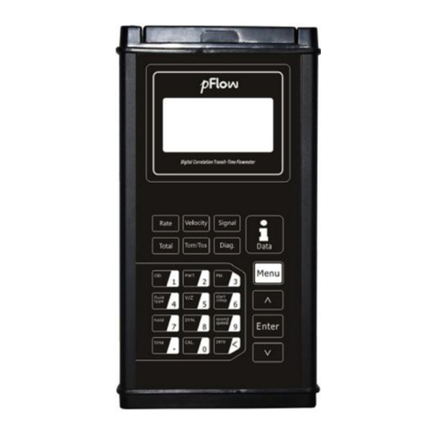
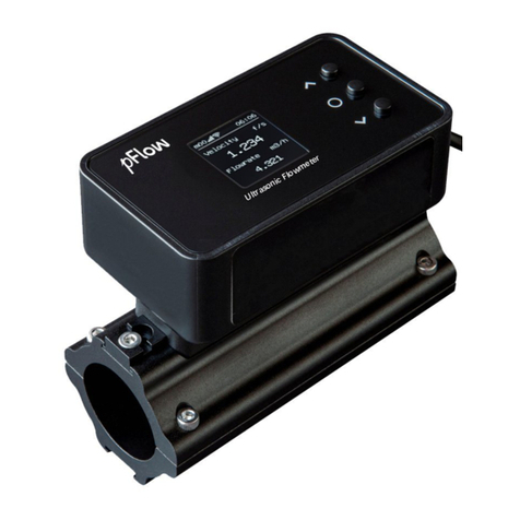
PFlow Industries P117 User manual

Reversion:3.0.0
Ultrasonic Flowmet
Model:
Update
Record
P117
Ultrasonic Flowmeter
Ultrasonic Flowmet
er Instruction M
anual
Model:
P117
Revision
3.0.0
Date 06 . 2019
Ultrasonic Flowmeter
Page1of51
anual

Reversion:3.0.0
Notice
Thankyou forchoosing the P117
Ultrasonic Flowmeter
sending technology.
Thisinstruction manualcontainsimportantinformation. Pleaseread
thusavoiding damage to the flowmeter
from
Thisinstruction manualwill advise
howto use the flowmeterstep
description, installation, wiring and
quick setupetc. to make it easierto operate.
Aworking knowledgeofthemenu settings
willassist
function.
Warning
Maycause injury.
Attention
Maydamage the flowmeter
Some ofthe instructionsmaybe different
from
the configuration requirements
. It also maybe due to changesin productdesign, modification and upgrade .You
will find the flowmeterdisplayinterface intuitive and easyto understand and it shall prevail when t
indication ofthe instructions.P
lease referto the version number
P117
Ultrasonic Flowmeter
and Analyzerwith ARMchip and low-
voltage wide
Thisinstruction manualcontainsimportantinformation. Pleaseread
it
carefullybefore operation the flowmeter
from
improperuse.
howto use the flowmeterstep
-by-step manner
, including productcomponent
quick setupetc. to make it easierto operate.
willassist
you in understanding the
flowmeters powerfuland output
Maydamage the flowmeter
.
from
the flowmeterand analyzeryou havepurchased
. That
. It also maybe due to changesin productdesign, modification and upgrade .You
will find the flowmeterdisplayinterface intuitive and easyto understand and it shall prevail when t
lease referto the version number
and the appendix
formore information
Ultrasonic Flowmeter
Page2of51
voltage wide
-pulse
carefullybefore operation the flowmeter
, including productcomponent
flowmeters powerfuland output
. That
dependson
. It also maybe due to changesin productdesign, modification and upgrade .You
will find the flowmeterdisplayinterface intuitive and easyto understand and it shall prevail when t
here isno
formore information
.

Reversion:3.0.0
ProductComponents
Inspection should be made before installing the
the packing list
. Make sure thatthere isno damage to theenclosure due to loose screworwire
thatmayhave occurred during transportation. Anyquestions, please contactyourrepresentative assoon as
possible.
Transmitter
Accessories
Cable
Carrying Case
SignalCable
PipeStraps
Software
CouplingCompound
Charger
OD.12 3
4 5 6
7 8 9
0
.
PWT. PM.
fluid
type V/Z star
/stop
hold DYN. sound
speed
time CAL. zero
Rate Velocity Signal
GraphTotal Diagnostics Data
Enter
P117
Ultrasonic Flowmeterand Analyzer
P117
Ultrasonic Flowmeter
Inspection should be made before installing the
f
lowmeter. Check to see if the spareparts are in accordance with
. Make sure thatthere isno damage to theenclosure due to loose screworwire
s
orotherdamage
thatmayhave occurred during transportation. Anyquestions, please contactyourrepresentative assoon as
Transducer
Documents
SignalCable
PipeStraps
Charger
1.Instruction
2.PackingList
3.
Certified FactoryCalibration
Ultrasonic Flowmeter
Page3of51
lowmeter. Check to see if the spareparts are in accordance with
orotherdamage
thatmayhave occurred during transportation. Anyquestions, please contactyourrepresentative assoon as
Certified FactoryCalibration

Reversion:3.0.0
1
Transmitter Installationand Connection
1.1 Power SupplyConnections
................................
1.1.1 TypeofPower Supply
................................
1.1.2 Wiring................................
................................
1.1.3 Data OutputWiring
................................
1.2 Powering On................................
................................
1.3 KeypadFunctions
................................
1.4 KeypadOperation
................................
1.5 Flowmeter Menu Descriptions
................................
2TheQuickSetupDescription
................................
2.1
Double FunctionKeysMenuDescription
2.2 For example................................
................................
2.3 MeasurementSite Selection
................................
3Transducer Installation
................................
3.1 InstallingtheTransducer
................................
3.1.1
Transducer Mounting Methods
3.1.2 VMethod................................
................................
3.1.3 ZMethod ................................
................................
3.1.4
NMethod (notcommonlyused)
3.2 Transducer InstallationandFixing
................................
3.3 Transducer Mounting Inspection
................................
3.3.1 Signal Strength
................................
3.3.2 Signal Quality(Qvalue)
................................
3.3.3 Total TimeandDelta Time
................................
3.3.4 Transit TimeRatio
................................
3.3.5 Warnings................................
................................
4Operating Instructions
................................
4.1 SystemNormal Identification
................................
4.2 LowFlowCutoff Value
................................
4.3 Zero Settings................................
................................
4.4 Scale Factor................................
................................
4.5 4~20mACurrentLoop Output
................................
4.6
4~20mAAnalogOutputCalibration
4.7 TFCard Operation
................................
4.7.1 Specifications
................................
4.7.2 ReadingtheTFData Offline
................................
4.7.3
TFCard StorageOperationGuide
P117
Ultrasonic Flowmeter
Content
Transmitter Installationand Connection
................................
................................
................................
................................................................
................................
................................
................................................................
...............................
................................
................................
................................
................................
................................................................
................................
................................
................................
................................
................................
................................................................
................................
................................
................................................................
................................
................................
................................................................
.........................
................................
................................
................................
Double FunctionKeysMenuDescription
................................................................
................................
................................
................................
................................
................................
................................................................
.............................
................................
................................
................................
................................
................................................................
................................
Transducer Mounting Methods
................................................................
................................
................................
................................
................................
................................
................................
................................
NMethod (notcommonlyused)
................................................................
................................
................................
................................
................................
................................
................................
................................
................................
................................................................
................................
................................
................................................................
..........................
................................
................................
................................
................................
................................................................
................................
................................
................................
................................
................................
................................
................................
................................
................................................................
..........................
................................
................................................................
................................
................................
................................
................................
................................
................................
................................
................................
................................
................................
4~20mAAnalogOutputCalibration
................................................................
................................
................................
................................................................
................................
................................
................................................................
................................
................................
................................
................................
TFCard StorageOperationGuide
................................................................
................................
Ultrasonic Flowmeter
Page4of51
................................
.................6
................................
6
...............................
6
................................
........................6
................................
...7
................................
......................8
................................
...............8
................................
..............9
.........................
10
................................
...11
................................
........11
................................
......................15
.............................
17
................................
............19
................................
..19
................................
................19
................................
.................19
................................
.................19
................................
..............20
................................
...................20
................................
......................20
................................
.........21
..........................
21
................................
......................21
................................
...21
................................
..................21
................................
.............23
..........................
23
................................
...23
................................
....................23
................................
......................23
................................
.......................23
................................
................24
................................
...........24
................................
...........24
................................
....................25
................................
...........25
Reversion:3.0.0
4.8 ESN................................
................................
5WindowDisplay Explanations
................................
5.1 WindowDisplayCodes
................................
5.2 DisplayExplanation
................................
6ErrorDiagnoses
................................
6.1
Table 1. Error CodesandSolutions(during operation)
6.2
FrequentlyAskedQuestionsandAnswers
7Product Overview
................................
7.1 Introduction................................
................................
7.2 FeaturesofFlowmeter
................................
7.3 TheoryofOperation
................................
7.4 Applications................................
................................
7.5 Specifications................................
................................
8Appendix 1 -
FlowApplicationData
8.1
SoundVelocityandViscosityfor FluidsCommonlyUsed
8.2
SoundVelocityfor VariousMaterialsCommonlyUsed
8.3
SoundVelocityInWater (1 atm)AtDifferentTemperatures
Update Information:
__________________________________________________________________________________________
__________________________________________________________________________________________
______________________________________
__________________________________________________________________________________________
P117
Ultrasonic Flowmeter
................................
................................................................
................................
................................
................................
................................
................................
................................................................
................................
................................
................................................................
................................
................................
................................................................
........................
Table 1. Error CodesandSolutions(during operation)
................................
................................
FrequentlyAskedQuestionsandAnswers
................................................................
................................
................................
................................................................
.....................
................................
................................
................................
................................
................................................................
................................
................................
................................................................
................................
................................
................................
................................
................................
................................
................................
FlowApplicationData
................................................................
.......................
SoundVelocityandViscosityfor FluidsCommonlyUsed
................................
................................
SoundVelocityfor VariousMaterialsCommonlyUsed
................................
................................
SoundVelocityInWater (1 atm)AtDifferentTemperatures
................................
................................
__________________________________________________________________________________________
__________________________________________________________________________________________
______________________________________
____________________________________________________
__________________________________________________________________________________________
Ultrasonic Flowmeter
Page5of51
................................
..26
................................
.27
................................
....27
................................
.........28
........................
46
................................
....................46
................................
.......47
.....................
48
................................
......................48
................................
......48
................................
.........48
................................
.....................49
................................
...................49
.......................
50
................................
.............50
................................
..................50
................................
..........51
__________________________________________________________________________________________
__________________________________________________________________________________________
____________________________________________________
__________________________________________________________________________________________

Reversion:3.0.0
1
TransmitterInstallation and Connection
1.1
PowerSupplyConnections
1.1.1 TypeofPower Supply
The factoryoffers one r
echargeable 11.1VLithiumbatteryand matching batterycharger.
1.1.2 Wiring
Openthe hinged top coverofthe electronics.
Downstreamtransducerconnector, upstreamtransducerconnector,SDcard s
connectorand batteryrecharge port.
Warning
Wiring
connectionsshould be made
P117
Ultrasonic Flowmeter
TransmitterInstallation and Connection
PowerSupplyConnections
echargeable 11.1VLithiumbatteryand matching batterycharger.
Openthe hinged top coverofthe electronics.
The wiring ports ofthe P117, fromleft to right, are
asfollows:
Downstreamtransducerconnector, upstreamtransducerconnector,SDcard s
lot, powerswitch, d
ata
connectionsshould be made
when powerisoff.
Ultrasonic Flowmeter
Page6of51
asfollows:
ata
output

Reversion:3.0.0
1.1.3 DataOutputWiring
Data outputwiring asshownbelow: Firstconnectthe 8
ABwith the RS485 Communication, finallygetthe Iwith the 4 ~20mAcurrentoutput.
ABI+ I-
RS485and4~20mA
Output
P117
Ultrasonic Flowmeter
Data outputwiring asshownbelow: Firstconnectthe 8
-pin plug with the data outputport;
afterthese connectthe
ABwith the RS485 Communication, finallygetthe Iwith the 4 ~20mAcurrentoutput.
OCT+OCT- RL1RL2
Dataoutputportto
thetransmitter(8
Ultrasonic Flowmeter
Page7of51
afterthese connectthe
Dataoutputportto
thetransmitter(8
-pin)

Reversion:3.0.0
1.2 PoweringOn
When the meterispowered on, it will start with the following screen, the Version NumberVer:
numberS/N:v5200355
will be shown atthe bottomrightcorner.
Ifitisthe firsttime ofuse oran installation
on a newsite,the customerneed
parameters. Anyparameters which are setby
user.
When the usermodifiesthe parameters or
removesthe transducers, the meterwill recalculate automatically, and
operate normallywith the newlyset
parameters.
1.3 KeypadFunctions
Followthese guidelineswhen using the fl
owmeterkeypad:
~and :Inputnumbers.
:
Backspace ordelete characters to the left.
and :Return to the last
Menu
open the nextMenu. Actsas"+"and "-"
are used to
enternumbers.
:Selecta Menu
.Press thiskeyfirst, inputa
two-digit Menu numberand the selected
Menu
will be displayed. Forexample, in orderto
inputa
pipe outside diameter, press
where "11"
isthe windowIDto displaythe
pipe outside diameter.
:Enter/Confirm.
:Enter/Exit SDcard storage interface.
Velocity, SignalQuality, POS Totalizer,
waveform
P117
Ultrasonic Flowmeter
When the meterispowered on, it will start with the following screen, the Version NumberVer:
1
.0
will be shown atthe bottomrightcorner.
on a newsite,the customerneed
s
to inputthe newinstallation site
parameters. Anyparameters which are setby
the userwillbe saved permanentl
yuntil theyare changed bythe
removesthe transducers, the meterwill recalculate automatically, and
parameters.
owmeterkeypad:
Backspace ordelete characters to the left.
Menu
or
are used to
.Press thiskeyfirst, inputa
Menu
data
inputa
isthe windowIDto displaythe
:Enter/Exit SDcard storage interface.
are shortcutstothe windowsfor
waveform
, and Diagnosis.
Ultrasonic Flowmeter
Page8of51
.0
1 andthe Serial
to inputthe newinstallation site
yuntil theyare changed bythe
removesthe transducers, the meterwill recalculate automatically, and
FlowRate,

Reversion:3.0.0
1.4 KeypadOperation
Th
e instrumentsetup and measurementdisplaysare subdivided into more than 100 independent
operatorcan i
nputparameters, modifysettingsordisplaymeasurementresultsby
These Menusarearranged by 2-
digit serialnumbers from00~99, then using +0, +1, etc. Each
defined meaning. Forexample, Menu 11
indicates
mounting spacing between the transducers.Each
1.To visit a specific Menu, press the
2-digit Menu IDcode and thatMenu
will be displayed.
press the
keysforwindowIDcode 11.
Anothermethod to visit a particularMenu
isto press the
Menus. Forexample, if the currentMenu is
30
again to enterMenu 30.
The Menusaredivided into three types:1)Data Type
DisplayType, such asM00, M01.
Visit Data Type Menusto check specific
parameters.
Ifparameterchange isneeded, justpress
first, then inputthe valuesand press
confirm.
Example 1:To enterapipe outerdiameterof
200mm, the procedure isasfollows:
Press to enterMenu
11 (
numericalvalue displayed currentlyisthe previous
pipe outerdiameter). Nowpress the
key. The
symbol">"and a flashing cursoris
displayed
screen.The newvalue can nowbe entered.
Visit Selection Type Menusto check the related
options. Ifneed to modifyit,press
first to
enterthe revised selection when the symbol
displayed on the screen;
orinputnumbers directlyto
selectthe option when the symbol">"and a flashing
cursorare displayed.
Example 2:Ifthe pipe materialis"
Carbon Steel",
press
to enterMenu 14,
then press to modifythe option.
Then,
select"0. Carbon Steel"fromthe drop-
down
(
you maycycle through the choicesbypressing the
and keys)and then press
to confirmthe selection.
P117
Ultrasonic Flowmeter
e instrumentsetup and measurementdisplaysare subdivided into more than 100 independent
Menu
nputparameters, modifysettingsordisplaymeasurementresultsby
"visiting"
a specific
digit serialnumbers from00~99, then using +0, +1, etc. Each
Menu
indicates
the pipe outside diameter, while Menu 25 i
ndicates
mounting spacing between the transducers.Each
Menu will be discussed laterin thismanual.
keyatanytime exceptthe
SDCard Storage Interface
will be displayed.
Forexample, to inputorcheck the pipe outside diameter,
keysforwindowIDcode 11.
isto press the
,and
keysto scroll through the
30
, press key to enterMenu 31, press the
The Menusaredivided into three types:1)Data Type
, such asM11, M12;2)Selection Type
, such
parameters.
to
Example 1:To enterapipe outerdiameterof
11 (
the
numericalvalue displayed currentlyisthe previous
key. The
displayed
on the
Visit Selection Type Menusto check the related
first to
">"is
orinputnumbers directlyto
selectthe option when the symbol">"and a flashing
Carbon Steel",
to enterMenu 14,
Then,
down
Menu
you maycycle through the choicesbypressing the
Ultrasonic Flowmeter
Page9of51
Menu
s.The
a specific
Menu.
Menu
IDcode hasa
ndicates
the
SDCard Storage Interface
, then inputthe
Forexample, to inputorcheck the pipe outside diameter,
keysto scroll through the
button
, such
asM14;3)

Reversion:3.0.0
1.5 FlowmeterMenu
Descriptions
These windowsareassigned asfollows:
00~09DisplayMenu
s:Usedtodisplay flowrate, positive total,negativetotal,nettotal, velocity,date
&timeetc.
10~29Setup Menu
s:Used to enterpipe outerdiameter, pipe wall thickness, f
type, transducermounting and spacing, etc.
30~38
Flowunitsselection and totalizeroperating
/resetthe varioustotalizermodes.
40~45Setup Menus:
Zero SetCalibration me
46~81Inputand outputsetup Menu
s:currentloop mode select, 4mAor
90~96
Diagnostics:signalstrength quality(
(Menu
92), totaltime anddelta time ofthe
Kfactor(Menu 94).
-04~20mAcorrection Menu.
Attention
"Hidden"Menu
sare forhardware adjustment(
P117
Ultrasonic Flowmeter
Descriptions
s:Usedtodisplay flowrate, positive total,negativetotal,nettotal, velocity,date
s:Used to enterpipe outerdiameter, pipe wall thickness, f
luid type, transducer
type, transducermounting and spacing, etc.
Flowunitsselection and totalizeroperating
Menus:Used to select
unitsofmeasurement. Other
Zero SetCalibration me
nu, Scale Factormenu, etc.
s:currentloop mode select, 4mAor
2
0mAoutputvalue, etc.
Diagnostics:signalstrength quality(
Menu 90), TOM/TOS*100 (Menu
91),sound velocity
92), totaltime anddelta time ofthe
measured signal(Menu
93), Reynoldsnumberand
sare forhardware adjustment(
retained bythe manufacturer).
Ultrasonic Flowmeter
Page10of51
s:Usedtodisplay flowrate, positive total,negativetotal,nettotal, velocity,date
luid type, transducer
unitsofmeasurement. Other
Menusset
0mAoutputvalue, etc.
91),sound velocity
93), Reynoldsnumberand

Reversion:3.0.0
2
TheQuickSetup Description
2.1 DoubleFunction KeysM
enu
Press to display FlowRate
with large font
Press to display V
elocitywith large font
Press to display SignalQuality
with large font
Press to displayPOS Total
with large font
P117
Ultrasonic Flowmeter
TheQuickSetup Description
enu
Description
with large font
.
elocitywith large font
.
with large font
.
with large font
.
Ultrasonic Flowmeter
Page11of51

Reversion:3.0.0
Press to displayMetric/English.
The function is
the same with .
Press to display
the CurrentState ofthe
System.
Press to displayPipe Outside D
iameter.
function isthe same with
Press to displayPipe
Wall Thickness
function isthe same with
Menu 30
P117
Ultrasonic Flowmeter
The function is
the CurrentState ofthe
iameter.
The
.
Wall Thickness
.The
.
Ultrasonic Flowmeter
Page12of51

Reversion:3.0.0
Press to displayPipe Material.
The function is
the same with .
Press to displayFluid Type.
The function is
the same with .
Press to display
TransducerMounting Methods
The function isthe same with
Press to
Start /Stop ManualAccumulation
Totalin turn.
P117
Ultrasonic Flowmeter
The function is
The function is
TransducerMounting Methods
.
.
Start /Stop ManualAccumulation
Ultrasonic Flowmeter
Page13of51

Reversion:3.0.0
Press toDisplay/Hold Total
in turn.
Press to displayTOM/TOS.
The function is
the same with .
Press to displayFluid Sound V
elocit
function isthe same with
Press to display
Date and Time. The function
isthe same with .
P117
Ultrasonic Flowmeter
in turn.
The function is
elocit
y. The
.
Date and Time. The function
Ultrasonic Flowmeter
Page14of51

Reversion:3.0.0
Press to enterManualCalibrate.
Afterthe flow
velocitybecomessteady, input
standard totalizerto get
the Kfactor. Then press
to complete the
calibration.
Press t
o inputthe password1234 to resetzero.
2.2 For example
ForExample:Letusassume you have a DN
150
with no liner. These parameters should be
operat
Step 1. Pipe OuterDiameter
Press
keysto enter
enterthe Pipe Outside D
iameter, then press the
key.
Step 2. Pipe Wall Thickness
Press the
keyto enter
12 the Pipe Wall Thickness,then press the
key.
P117
Ultrasonic Flowmeter
Afterthe flow
standard totalizerto get
to complete the
o inputthe password1234 to resetzero.
150
(6")pipe, measuring mediumis
water, Materialiscarbon steel
operat
ed asfollows:
keysto enter
Menu 11,
iameter, then press the
keyto enter
Menu
Ultrasonic Flowmeter
Page15of51
water, Materialiscarbon steel

Reversion:3.0.0
Step 3. Pipe Material
Press the keyto
enter
14, press the key, use the
or
keyto selectthe pipe materialfromthe drop
-
Menu, thenpress the key.
Step 4. Liner MaterialParameters
(including thickness and sound velocity, if needed
Press the
keyto enter
16, press the key, use the
or
keyto selectlinermaterialfromthe drop-
down
and then press the key.
Step 5. FluidType
Press the
keyto enter
20, press the key, use the
or
keyto selectfluid type fromthe drop-down
Men
press the key.
Step 6. Transducer Mounting
Press the
keyto enter
24, press the key, use the
or
keyto selecttransducer-
mounting fromthe drop
Menu, thenpress the key.
(Detailson Chapter3.1.1 ).
P117
Ultrasonic Flowmeter
enter
Menu
or
-down
(including thickness and sound velocity, if needed
):
keyto enter
Menu
or
down
Menu,
keyto enter
Menu
or
Men
u, then
keyto enter
Menu
or
mounting fromthe drop
-down
Ultrasonic Flowmeter
Page16of51

Reversion:3.0.0
Step 7. Transducer Spacing
Press the
keyto enter
25, accuratelyinstallthe transduceraccording to the
displayed transducermounting spacing and the selected
mounting method.
(Detailson Chapter2.3 ).
Step 8. Display MeasurementResults
Press
to enterMenu 01 to
displayflowrate. (Subjectto the realmeasurement. )
2.3
MeasurementSiteSelection
Compared with otherkindsofflowmeters, Ultrasonic Flowmeteristhe simplestone to install. Choose a proper
measurementsite, enterthe pipe
sparameters into the flowmeter.Install and fix the transducers on the pipe as
instructed bythe meterand start the measurement.
When selecting ameasurementsite, it isimportantto selectan area where thefluid flowprofile isfullydeveloped
to guar
antee a highlyaccurate measurement. Use the following guidelinesto selecta properinstallation site:
l
Choosea section ofpipe thatisalwaysfullofliquid, such asa verticalpipe with flowin the upwarddirection
ora full horizontalpipe.
lEnsure enou
gh straightpipe length atleastequalto the figure shown belowforthe upstreamand downstream
transducers installation.
l
On the horizontalpipe, thetransducershould be mounted on the
section, avoid the 6 o clock and 12 o
clock
sedimentatthe bottom, orair bubblesorcavitation.
lEnsure thatthe
pipe surface temperature atthe
lConside
rthe inside condition ofthe pipe carefully.Ifpossible, selecta section ofpipewhere the inside is
free ofexcessive corrosion orscaling.
l
Choosea section ofsound conducting pipe.
P117
Ultrasonic Flowmeter
keyto enter
Menu
25, accuratelyinstallthe transduceraccording to the
displayed transducermounting spacing and the selected
to enterMenu 01 to
displayflowrate. (Subjectto the realmeasurement. )
MeasurementSiteSelection
Compared with otherkindsofflowmeters, Ultrasonic Flowmeteristhe simplestone to install. Choose a proper
sparameters into the flowmeter.Install and fix the transducers on the pipe as
instructed bythe meterand start the measurement.
When selecting ameasurementsite, it isimportantto selectan area where thefluid flowprofile isfullydeveloped
antee a highlyaccurate measurement. Use the following guidelinesto selecta properinstallation site:
Choosea section ofpipe thatisalwaysfullofliquid, such asa verticalpipe with flowin the upwarddirection
gh straightpipe length atleastequalto the figure shown belowforthe upstreamand downstream
On the horizontalpipe, thetransducershould be mounted on the
3 o clock and 9 o
clock position
clock
position, in orderto avoid
the signalattenuation caused by
sedimentatthe bottom, orair bubblesorcavitation.
pipe surface temperature atthe
measuring pointiswithin
the transducertemperature limits.
rthe inside condition ofthe pipe carefully.Ifpossible, selecta section ofpipewhere the inside is
Choosea section ofsound conducting pipe.
Ultrasonic Flowmeter
Page17of51
Compared with otherkindsofflowmeters, Ultrasonic Flowmeteristhe simplestone to install. Choose a proper
sparameters into the flowmeter.Install and fix the transducers on the pipe as
When selecting ameasurementsite, it isimportantto selectan area where thefluid flowprofile isfullydeveloped
antee a highlyaccurate measurement. Use the following guidelinesto selecta properinstallation site:
Choosea section ofpipe thatisalwaysfullofliquid, such asa verticalpipe with flowin the upwarddirection
gh straightpipe length atleastequalto the figure shown belowforthe upstreamand downstream
clock position
ofthe pipe
the signalattenuation caused by
the
the transducertemperature limits.
rthe inside condition ofthe pipe carefully.Ifpossible, selecta section ofpipewhere the inside is

Reversion:3.0.0
Pump
Valve
Reduce
Diffuser
Tee
90
o
bend
Straightlengthofupstream
piping
Name
10Dmin
0.5D min 10D min
10Dmin
L
D
5Dmin
Flowcontrolledupstream
P
Stopvalve
P117
Ultrasonic Flowmeter
Straightlength of
downstreampiping
Straightlengthofupstream
Detector
L≥5D
L ≥5D
L≥10D
Flowcontrolleddownstream
L ≥10D
L ≥5D
L ≥10D
L ≥50D
L
≥30D
D
L≥10D
L≥30D
Flowcontrolledupstream
L≥50D
P
Check valve
Stopvalve
Ultrasonic Flowmeter
Page18of51
Flowcontrolleddownstream

Reversion:3.0.0
3TransducerInstallation
3.1 InstallingtheTransducer
Before install
ing the transducers, clean the pipe surface where the transducers are to be mounted. Remove anyrust,
scale orloose paintand make a smooth surface. Choose asection ofsound conductingpipe forinstalling the
transducers.Applya wide ban
d ofsonic coupl
well ason the pipe surface,
ensure there are no air bubblesbetween the transducers and the pipe wall,
attach the transducers to the pipe with the strapsprovided and tighten themsec
Note:
1.
The two transducers shouldbe mounted atthe pipe scenterline on horizontalpipes.Make sure thatthe
transducermounting direction isparallelwith the flow.
2.
During the installation, thereshould be no air bubblesorparticlesbetween the t
On horizontalpipes, the transducers shouldbe mounted in the 3 o clock and 9 o clockpositionsofthe pipe
section in orderto avoid anyair bubblesinside the top portion ofthe pipe.
3. Referto 2.15 forthe
TransducerMounting
4.
Ifthe transducers cannotbe mounted horizontallysymmetricallydue to limitation ofthe localinstallation
conditions, it maybe necessarytomountthe transducers ata location where there isa guarantee
condition (the pipe isalways
full ofliquid).
3.1.1 TransducerMountingMethods
Three
transducermounting methodsare available. Theyare respectively:Vmethod, Zmethod
The Vmethod isprimarilyused on small diameterpipes(DN100
ap
plicationswhere the Vmethod cannotwork due topoorsignalorno signaldetected. In addition, the Zmethod
generallyworksbetteron largerdiameterpipes(overDN300mm, 12
The Nmethod isan uncommonlyused method.
3.1.2 VMethod
The Vmethod isconsidered asthe standard method. Itusuallygivesa more accurate reading and isused on pipe
diameters ranging from25mmto 400mm(1
"~
properinstallation ofthe transducers
, contacton the pipe atthe pipe scenterline and equalspacing on eitherside
ofthe centerline.
3.1.3 ZMethod
The signaltransmitted in a Zmethod installation hasless attenuation than a signaltr
method
when the pipesaretoo large,there are some suspended solid in the fluid, orthe
Thisisbecausethe Zmethod utilizesa directlytransmitted (ratherthan reflected)signalwhich transversest
liquid onlyonce. TheZmethod isable to measure on pipediameters ranging from100mm
200"
)approximately. Therefore, we recommend the Zmethod forpipe diameters over300mm (12
DownstreamTransducer
UpstreamTransducer
Flow
SideView
P117
Ultrasonic Flowmeter
ing the transducers, clean the pipe surface where the transducers are to be mounted. Remove anyrust,
scale orloose paintand make a smooth surface. Choose asection ofsound conductingpipe forinstalling the
d ofsonic coupl
ing compound down thecenterofthe face ofeach transduceras
ensure there are no air bubblesbetween the transducers and the pipe wall,
attach the transducers to the pipe with the strapsprovided and tighten themsec
urely.
The two transducers shouldbe mounted atthe pipe scenterline on horizontalpipes.Make sure thatthe
transducermounting direction isparallelwith the flow.
During the installation, thereshould be no air bubblesorparticlesbetween the t
ransducerand the pipe wall.
On horizontalpipes, the transducers shouldbe mounted in the 3 o clock and 9 o clockpositionsofthe pipe
section in orderto avoid anyair bubblesinside the top portion ofthe pipe.
TransducerMounting
Spacing.
Ifthe transducers cannotbe mounted horizontallysymmetricallydue to limitation ofthe localinstallation
conditions, it maybe necessarytomountthe transducers ata location where there isa guarantee
full ofliquid).
transducermounting methodsare available. Theyare respectively:Vmethod, Zmethod
and
The Vmethod isprimarilyused on small diameterpipes(DN100
~300mm, 4"~12"
). The Zmethod isused in
plicationswhere the Vmethod cannotwork due topoorsignalorno signaldetected. In addition, the Zmethod
generallyworksbetteron largerdiameterpipes(overDN300mm, 12
")orcastiron pipes.
The Nmethod isan uncommonlyused method.
Itisused on
smallerdiameterpipes(belowDN50mm, 2
The Vmethod isconsidered asthe standard method. Itusuallygivesa more accurate reading and isused on pipe
"~
16")approximately. Also, it isconvenientto use
, butstill requires
, contacton the pipe atthe pipe scenterline and equalspacing on eitherside
The signaltransmitted in a Zmethod installation hasless attenuation than a signaltr
ansmitted with the V
when the pipesaretoo large,there are some suspended solid in the fluid, orthe
scaling
and linerare too thick
Thisisbecausethe Zmethod utilizesa directlytransmitted (ratherthan reflected)signalwhich transversest
liquid onlyonce. TheZmethod isable to measure on pipediameters ranging from100mm
to
5000
)approximately. Therefore, we recommend the Zmethod forpipe diameters over300mm (12
DownstreamTransducer
TransducerSpace
Flow
TopViewSection
PipeStrap
Transducer
Ultrasonic Flowmeter
Page19of51
ing the transducers, clean the pipe surface where the transducers are to be mounted. Remove anyrust,
scale orloose paintand make a smooth surface. Choose asection ofsound conductingpipe forinstalling the
ing compound down thecenterofthe face ofeach transduceras
ensure there are no air bubblesbetween the transducers and the pipe wall,
and then
The two transducers shouldbe mounted atthe pipe scenterline on horizontalpipes.Make sure thatthe
ransducerand the pipe wall.
On horizontalpipes, the transducers shouldbe mounted in the 3 o clock and 9 o clockpositionsofthe pipe
Ifthe transducers cannotbe mounted horizontallysymmetricallydue to limitation ofthe localinstallation
conditions, it maybe necessarytomountthe transducers ata location where there isa guarantee
d full pipe
and
Nmethod.
). The Zmethod isused in
plicationswhere the Vmethod cannotwork due topoorsignalorno signaldetected. In addition, the Zmethod
smallerdiameterpipes(belowDN50mm, 2
").
The Vmethod isconsidered asthe standard method. Itusuallygivesa more accurate reading and isused on pipe
, butstill requires
, contacton the pipe atthe pipe scenterline and equalspacing on eitherside
ansmitted with the V
and linerare too thick
.
Thisisbecausethe Zmethod utilizesa directlytransmitted (ratherthan reflected)signalwhich transversest
he
5000
mm(4"to
)approximately. Therefore, we recommend the Zmethod forpipe diameters over300mm (12
").
TransducerSpace

Reversion:3.0.0
3.1.4
NMethod (notcommonlyused)
With the Nmethod, the
sound wavestraverse the fluid
suitable forsmallpipe diametermeasurement.
transit distance with the Nmethod (
uncommonlyused
3.2 Transdu
cerInstallation andFixing
Transducers can be installed onto the pipe with itsmagnetic racks. Ifyou need to fasten them, then you can use
the chainsto make it firm. Showasbelow:
3.3
TransducerMounting Inspection
Confirmthe transducerisinstalled pr
operlybychecking the detected signalstrength,totaltransit time, delta time
aswell astransit time ratio Key9.
The "mounting"
condition directlyinfluencesthe flowvalue accuracyand system
Inmostinstancesit isonlynecessary
applya wide b
transducerand stick it to the outside pipe wall to getgood measurementresults. However, the following
still need to be carried outinorderto ensure
instrument.
DownstreamTransducer
UpstreamTransducer
Flow
SideView
DownstreamTransducer
UpstreamTransducer
Flow
SideView
P117
Ultrasonic Flowmeter
NMethod (notcommonlyused)
sound wavestraverse the fluid
three timesand bounce twice
offthe pipe walls. Itis
suitable forsmallpipe diametermeasurement.
The measurementaccuracycan be improved byextending the
uncommonlyused
).
cerInstallation andFixing
Transducers can be installed onto the pipe with itsmagnetic racks. Ifyou need to fasten them, then you can use
TransducerMounting Inspection
operlybychecking the detected signalstrength,totaltransit time, delta time
condition directlyinfluencesthe flowvalue accuracyand system
long-
termoperation
applya wide b
an
d ofsonic coupling compound lengthwise on the faceofthe
transducerand stick it to the outside pipe wall to getgood measurementresults. However, the following
still need to be carried outinorderto ensure
ahigh reliabilityofthe measurementand long-
termoperation ofthe
DownstreamTransducer
TransducerSpacing
Flow
TopViewSection
PipeStrap
Transducer
DownstreamTransducer
TransducerSpacing
Flow
TopViewSection
PipeStrap
Transducer
Ultrasonic Flowmeter
Page20of51
offthe pipe walls. Itis
The measurementaccuracycan be improved byextending the
Transducers can be installed onto the pipe with itsmagnetic racks. Ifyou need to fasten them, then you can use
operlybychecking the detected signalstrength,totaltransit time, delta time
termoperation
reliability.
d ofsonic coupling compound lengthwise on the faceofthe
transducerand stick it to the outside pipe wall to getgood measurementresults. However, the following
checks
termoperation ofthe
TransducerSpacing
TransducerSpacing
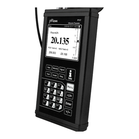
Other manuals for P117
2
Table of contents
Other PFlow Industries Measuring Instrument manuals

PFlow Industries
PFlow Industries P117 User manual

PFlow Industries
PFlow Industries D116 User manual

PFlow Industries
PFlow Industries P118i User manual

PFlow Industries
PFlow Industries D116 User manual

PFlow Industries
PFlow Industries P117 User manual

PFlow Industries
PFlow Industries D118 User manual

PFlow Industries
PFlow Industries P116 User manual

PFlow Industries
PFlow Industries F2 User manual