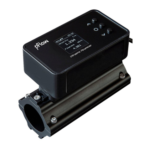
PFlow Industries P116 User manual

Ultrasonic Flowmeter Instruction Manual
Model: P116
Update
Record
Revision
3.0.0
Date 11. 2015

P116 UltrasonicFlowmeter
Version:3.0.0 Page2of49
Notice
ThankyouforchoosingtheP116 UltrasonicFlowmeterandAnalyzerwithARMchip andlow-voltagewide-pulse
sendingtechnology.
Thisinstructionmanualcontainsimportantinformation.Pleasereadit carefullybeforeoperationtheflowmeter
thusavoidingdamagetotheflowmeterfromimproperuse.
Thisinstructionmanualwilladvisehowtousetheflowmeterstep-by-stepmanner,includingproductcomponent
description, installation, wiringandquicksetupetc. tomakeiteasiertooperate.
Aworking knowledgeofthemenusettingswill assistyouinunderstandingtheflowmeters powerfulandoutput
function.
Warning
Maycauseinjury.
Attention
Maydamagetheflowmeter.
Someoftheinstructionsmaybedifferentfromtheflowmeterand analyzeryouhavepurchased.Thatdependson
theconfigurationrequirements.Italsomaybeduetochangesinproductdesign,modificationand upgrade.You
will findtheflowmeterdisplayinterfaceintuitiveandeasytounderstandandit shall prevail whenthereisno
indicationoftheinstructions. Pleaserefertotheversionnumberandtheappendix formoreinformation.

P116 UltrasonicFlowmeter
Version:3.0.0 Page3of49
ProductComponents
Inspectionshouldbemadebeforeinstallingtheflowmeter.Checktosee ifthesparepartsareinaccordance with
thepackinglist.Makesurethatthereisnodamagetotheenclosureduetoloosescreworwiresorotherdamage
thatmayhaveoccurredduringtransportation.Anyquestions,pleasecontactyourrepresentativeassoonas
possible.

P116 UltrasonicFlowmeter
Version:3.0.0 Page4of49
Content
1.TransmitterInstallationand Connection...............................................................................................................6
1.1WireConnecting................................................................................................................................................6
1.1.1PowerSupplyOption....................................................................................................................................6
1.1.2TransmitterWiring......................................................................................................................................6
1.2PoweringOn......................................................................................................................................................6
1.3KeypadFunctions...............................................................................................................................................7
1.4KeypadOperation..............................................................................................................................................7
1.5FlowmeterMenuDescriptions............................................................................................................................8
2.TheQuickSetupInstructions................................................................................................................................9
2.1Doublefunctionkeysmenudescription...............................................................................................................9
2.2Forexample.....................................................................................................................................................13
2.3MeasurementSiteSelection..............................................................................................................................15
3.TransducerInstallation.........................................................................................................................................16
3.1InstallingtheTransducer...................................................................................................................................16
3.1.1TransducerMountingMethods..................................................................................................................17
3.1.2VMethod ..................................................................................................................................................17
3.1.3ZMethod ..................................................................................................................................................17
3.1.4NMethod(notcommonlyused).................................................................................................................17
3.2TransducerInstallationand Fixing.....................................................................................................................18
3.3TransducerMounting Inspection.......................................................................................................................18
3.3.1SignalStrength..........................................................................................................................................18
3.3.2SignalQuality(Qvalue)............................................................................................................................18
3.3.3TotalTimeandDeltaTime..........................................................................................................................18
3.3.4TransitTimeRatio.....................................................................................................................................19
3.3.5Warnings....................................................................................................................................................19
4.OperatingInstructions .........................................................................................................................................19
4.1SystemNormalIdentification...........................................................................................................................19
4.2LowFlowCutoff Value....................................................................................................................................19
4.3ZeroSettings....................................................................................................................................................20
4.4ScaleFactor.....................................................................................................................................................20
4.54~20mACurrentLoopOutput........................................................................................................................20
4.64-20mAAnalogOutputCalibration..................................................................................................................20
4.7TFCardOperation............................................................................................................................................21
4.7.1Specifications.............................................................................................................................................21
4.7.2InstallorRemovetheSD card whilethemeterispoweredon.....................................................................21
4.7.3ReadingtheTFDataOffline......................................................................................................................22
4.7.4SDCard StorageOperation........................................................................................................................22

P116 UltrasonicFlowmeter
Version:3.0.0 Page5of49
4.8ESN.................................................................................................................................................................23
5.WindowDisplay Explanations.............................................................................................................................24
5.1WindowDisplayCodes....................................................................................................................................24
5.2DisplayExplanation.........................................................................................................................................25
6.ErrorDiagnoses....................................................................................................................................................43
6.1Table1. Self-diagnosisandErrorSolutions.......................................................................................................43
6.2FrequentlyAskedQuestionsandAnswers.........................................................................................................43
7. ProductOverview.................................................................................................................................................45
7.1Introduction......................................................................................................................................................45
7.2Featuresof P116...............................................................................................................................................45
7.3TheoryofOperation.........................................................................................................................................45
7.4Applications.....................................................................................................................................................46
7.5Specifications...................................................................................................................................................47
8.Appendix1-FlowApplicationData.....................................................................................................................48
8.1SoundVelocityandViscosityforFluidsCommonlyUsed.................................................................................48
8.2SoundVelocityforVariousMaterialsCommonlyUse.......................................................................................48
8.3SoundVelocityInWater(1atm)AtDifferentTemperatures..............................................................................49
Updateinformation:
__________________________________________________________________________________________
__________________________________________________________________________________________
__________________________________________________________________________________________
__________________________________________________________________________________________

P116 UltrasonicFlowmeter
Version:3.0.0 Page6of49
1.TransmitterInstallationandConnection
1.1Wire Connecting
1.1.1PowerSupplyOption
Thefactoryoffersonerechargeable11.1VLithiumbatteryandmatchingbatterycharger.
1.1.2TransmitterWiring
Openthehingedtopcoveroftheelectronics.ShownfromlefttorightonthepaneloftheP116 arethe
downstreamtransducerconnector,upstreamtransducerconnector,thebatteryrechargeport(chargethetransmitter
orconnecttoastandbypowersupply), and the4~20mAoutputconnector.
Refertothebelowdiagramforspecificconnectioninformation:
Warning
Wirewhenitispower-off.Reliablegroundingmustbetakenfortheinstrumentbeforeinstallation
and use
1.2 PoweringOn
Assoonastheflowmeterisswitchedon,theself-diagnosisprogramwillstarttorun.Ifany errorisdetected,an
errorcodewill displayedonthescreen(see ErrorDiagnostics).Afterthat,thesystemwill runautomaticallyusing
theprogrammedparameters.
If it isthefirsttimetouseorinstall on anewsite,thecustomerneedtoinputthenewinstallationsiteparameters.
Anyparameterswhicharesetbytheuserwill besavedpermanentlyuntil theyarechangedbytheuser.
Whentheusermodifiestheparametersorremovesthetransducers,themeterwillrecalculateautomatically,and
operatenormallywiththenewlysetparameters.

P116 UltrasonicFlowmeter
Version:3.0.0 Page7of49
1.3KeypadFunctions
Followtheseguidelineswhenusingtheflowmeterkeypad:
~ and toinputnumbers.
Backspace ordeletecharacterstotheleft.
and Returntothelastmenuoropenthenextmenu.Acts
as “+”and “-”areusedtoenternumbers.
Selectamenu.Press thiskeyfirst,inputatwo-digit menunumber
and theselectedmenudatawillbedisplayed.Forexample,toinputapipe
outsidediameter,press where “11”isthewindow
IDtodisplaythepipeoutsidediameter. Enter/Confirm
Enter/Exit SDcardstorageinterface.
.AreshortcutstothewindowsforFlowRate,POSTotalizer,
Velocity, FluidType, SignalQualityandDiagnosis.
1.4KeypadOperation
Theinstrumentsetupand measurementdisplaysaresubdividedintomorethan100 independentmenus.The
operatorcaninputparameters,modifysettingsordisplaymeasurementresultsby “visiting”aspecificmenu.
Thesemenusarearrangedby2-digit serialnumbersfrom00~99, thenusing+0, +1, etc.EachmenuIDcodehasa
definedmeaning.Forexample,menu11isthepipeoutsidediameter,whilemenu25 isthemountingspacing
betweenthetransducers. Eachmenuisdiscussedlaterinthismanual.
Tovisitaspecificmenu,press the keyatanytimeexceptthe SDCardStorageInterface,theninputthe
2-digitmenuIDcodeandthatmenuwill bedisplayed.Forexample,toinputorcheckthepipeoutsidediameter,
press the keysforwindowIDcode11.
Anothermethodtovisitaparticularmenu istopress the and keystoscroll throughthe
menus. Forexample, ifthecurrentmenuis30, press keytoentermenu31, press the buttonagain
toentermenu30.
Themenusaredividedintothree types:
1)DataType, suchasM11, M12;
2)SelectionType, suchasM14;
3)Display Type, suchasM00, M01.
VisitDataTypemenustocheckspecificparameters. If
parameterchangeisneeded,justinputthevaluesthen
press ;orpress first,theninputthe
valuesandpress toconfirm.
Example1:Toenterapipeouterdiameterof200mm,
theprocedureisasfollows:
Press toenterMenu11(the
numericalvaluedisplayedcurrentlyistheprevious
Menu
:
11
Pipe OuterDiameter
168.00 mm
14
:
53
:
30 Q=97R

P116 UltrasonicFlowmeter
Version:3.0.0 Page8of49
pipeouterdiameter).Nowpress the key.The
symbol “>”and aflashingcursorisdisplayedon the
leftsideofthethirdlineon thescreen.Thenewvalue
cannowbeentered.Orinputthevaluefirstthenpress
toconfirm .
VisitSelectionTypemenustochecktherelated
options.Ifneedtomodifyit,press enterfirsttoenter
therevisedselectionwhenthesymbol “>”and a
flashingcursoraredisplayedattheleftendofthe
thirdlineonthescreen;orinputnumbersdirectlyto
selecttheoptionwhenthesymbol “>”and aflashing
cursoraredisplayed.
Example2:Ifthepipematerialis “Stainless Steel”,
press toenterMenu14, then
press tomodifytheoption.Then,select “1.
Stainless Steel”fromthedrop-downmenu(youmay
cyclethroughthechoicesbypressingthe and
keys)and thenpress toconfirmthe
selection.Itisalsopossibletopress the key
tochangetheselection and wait until “1. Stainless
Steel”isdisplayedon thesecondlineofthescreen.
Menu
:
14
PipeMaterial[14
1.StainlessSteel
14
:
54
:
45 Q=97R
Thenpress the keytoconfirm.
1.5FlowmeterMenuDescriptions
00~09 Displaymenus:Usedtodisplayflowrate,positivetotal, negativetotal,nettotal,velocity,date
&timeetc.
10~29 Setupmenus:Usedtoenterpipeouterdiameter,pipewall thickness,fluidtype,transducer
type, transducermountingand spacing, etc.
30~38 Flowunitsselectionandtotalizeroperatingmenus:Usedtoselectunitsofmeasurement.Othermenus
set/resetthevarioustotalizermodes.
40~45 ZeroSetCalibration, ScaleFactor.
55~83 Inputandoutputsetupmenus:currentloopmodeselect, 4mAor0mAoutputvalue, etc.
90~94 Diagnostics:signalstrengthquality(menu90),TOM/TOS*100 (menu91),soundvelocity
(menu92),totaltimeanddeltatimeofthemeasuredsignal(menu93),ReynoldsnumberandK
factor(menu94).
+0~+4Appendix:Poweron/off time, totalworkinghours,on/offtimesetc.
-04~20mAcorrectionmenu.
Attention
“Hidden”menusareforhardwareadjustment(setbythemanufacturer).

P116 UltrasonicFlowmeter
Version:3.0.0 Page9of49
2. TheQuickSetupInstructions
2.1Doublefunctionkeysmenudescription
Press
Press thedisplayFlowRateofM02.
Menu
:
02
FLOW0
.
0000m3/h
POS 744x1m3
14
:
47
:
42 Q=97R
Press
Press thedisplayVelocityofM01.
Menu
:
01
FLOW0
.
0000m3/h
Vel0
.
0000 m/s
14
:
43
:
02 Q=97R
Press
Press thedisplaySignalStrengthofM90.
Menu
:
90
Strength+Quality[90
UP
:
90
.
5DN
:
90
.
0Q=97
15
:
08
:
25 Q=97R
Press
Press theTotalofM00.
Menu
:
00
FLOW0
.
0000m3/h
NET 744x1m3
14
:
42
:
42 Q=97R

P116 UltrasonicFlowmeter
Version:3.0.0 Page10of49
Press
Press theTOM/TOSofM91.
Menu
:
91
Tom/Tos*100[91
0
.
00%
15
:
08
:
45 Q=97R
Press
Press thedisplaySystemofM08.
Menu
:
08
* R-----------------
Instrument Working
Properly
14
:
51
:
24 Q=97 R
Press
EnterinputPipeOuterDiameterofM11.
Menu
:
11
Pipe OuterDiameter
168.00 mm
14
:
53
:
30 Q=97R
Press
EnterinputPipeWall Thickness ofM12.
Menu
:
12
Pipe Wall Thickness
6
.
00mm
14
:
54
:
00 Q=97R

P116 UltrasonicFlowmeter
Version:3.0.0 Page11of49
Press
EntertheselectPipeMaterialtypeofM14.
Menu
:
14
PipeMaterial[14
0.CarbonSteel
14
:
54
:
45 Q=97R
Press
EntertheselectFluidTypeofM20.
Menu
:
20
Fluid Type [20
0
.
Water
14
:
55
:
58 Q=97R
Press
EntertheselectTransducerMounting ofM24.
Menu
:
24
Transducer Mounting
0
.
V
14
:
56
:
20 Q=97R
Press
Start/stopmanualtotalizerinturn.
Menu
202 sec
OFF 2.125m3
14
:
20
:
30 Q=00R

P116 UltrasonicFlowmeter
Version:3.0.0 Page12of49
Press
Show/keeptotalizerinturn.
Menu
FLOW10
.
2546m3/h
POS 230x1m3
14
:
20
:
30 Q=00R
Press
Displaydynamic/normalmodeinstantaneousflow
and flowvelocityinturn.
Menu
FLOW10
.
2546m3/h Dyn
Vel1
.
0250m/s
14
:
20
:
30 Q=00R
Press
EntertheFluidSoundVelocityofM92.
Menu
:
92
FluidSoundVelocity
0
.
0m/s
15
:
08
:
56 Q=97R
Press
EntersetuptimeofM60.
Menu
:
60
YY-MM-DDHH
:
MM
:
SS
10-03-08 15
:
05
:
00
15
:
05
:
00 Q=97R

P116 UltrasonicFlowmeter
Version:3.0.0 Page13of49
Press
Press enterthemanualcalibration offlow
velocity,press tomanualaccumulation,
thenpress accumulatedover,press
inputcriteriacumulants,confirmreasonable
press storetocompletethecalibration
coefficientK.
Menu
Manual Calibrate
Press ENT When Ready
14
:
20
:
30 Q=97R
Press
EnterthepasswordtoSetzerotoremove1234.
2.2 Forexample
Example:LetusassumeyouhaveaDN150(6”)pipe,measuringwater, Materialiscarbonsteelwithno liner.
Theseparametersshouldbeenteredasfollows:
Step1. Pipeoutsidediameter
Press keystoentermenu11,
enterthepipeoutsidediameter,thenpress the
key.
Menu
:
11
Pipe Outer Diameter
168.00 mm
14
:
53
:
30 Q=97R
Step2. Pipewall thickness
Press the keytoentermenu
12, enterthepipewall thickness (wall thickness for
variouspipeschedulescanbefoundintheappendix),
thenpress the key.
Menu
:
12
Pipe Wall Thickness
6
.
00 mm
14
:
54
:
00 Q=97R

P116 UltrasonicFlowmeter
Version:3.0.0 Page14of49
Step3. Pipematerial
Press the keytoentermenu 14,
press the key,usethe or key
toselectthepipematerialfromthedrop-downmenu,
thenpress the key.
Menu
:
14
Pipe Material[14
0.CarbonSteel
14
:
54
:
45 Q=97R
Step4. Linermaterialparameters
(includingthickness andsoundvelocity, ifneeded)
Press the keytoentermenu
16, press the key,usethe or
keytoselectlinermaterialfromthedrop-downmenu,
and thenpress the key.
Menu
:
16
LinerMaterial[16
0.None,Liner
14
:
55
:
10 Q=97R
Step5. Fluidtype
Press the keytoentermenu
20, press the key,usethe or
keytoselectfluidtypefromthedrop-downmenu,
thenpress the key.
Menu
:
20
Fluid Type[20
0
.
Water
14
:
55
:
58 Q=97R
Step6. Transducermountingmethods
Press the keytoentermenu
24, press the key,usethe or
keytoselecttransducer-mountingfromthedrop-down
menu, thenpress the key.
(Detailson Chapter4.1)
Menu
:
24
TransducerMounting
0
.
V
14
:
56
:
20 Q=97R

P116 UltrasonicFlowmeter
Version:3.0.0 Page15of49
Step7. Transducerspacing
Press the keytoentermenu
25, accuratelyinstall thetransduceraccordingtothe
displayedtransducermounting spacingandthe
selectedmounting method.
(Detailson Chapter4).
Menu
:
25
Transducer Spacing
131
.
82 mm
14
:
56
:
40 Q=97R
Step8. DisplayMeasurementResults
Press toenterMenu01 to
displayflowrate. (Subjecttotherealmeasurement.)
Menu
:
01
FLOW0
.
0000 m3/h
Vel0
.
0000 m/s
14
:
43
:
02 Q=97R
2.3 MeasurementSiteSelection
Comparingwithotherkindsofflowmeters,UltrasonicFlowmeteristhesimplestonetoinstall.Chooseaproper
measurementsite,enterthepipe sparametersintotheflowmeter, install andfix thetransducersonthepipe,thenit
canstartthemeasurement.
Whenselectingameasurementsite,it isimportanttoselectanareawherethefluidflowprofileisfullydeveloped
toguarantee ahighlyaccuratemeasurement. Usethefollowing guidelinestoselectaproperinstallation site:
lChooseasectionofpipethatisalwaysfull ofliquid, such asaverticalpipewithflowintheupwarddirection
orafull horizontalpipe.
lEnsureenoughstraightpipelength atleastequalto thefigureshown belowfortheupstreamanddownstream
transducersinstallation.
lOnthehorizontalpipe,thetransducershouldbemountedonthe3o clockand9o clockpositionofthepipe
section,avoidthe6o clockand 12 o clockposition,inordertoavoidthesignalattenuationcausedbythe
sedimentatthebottom, orairbubblesorcavitation.
lEnsurethatthepipesurface temperatureatthemeasuringpointiswithinthetransducertemperaturelimits.
lConsidertheinsideconditionofthepipecarefully.Ifpossible, selectasectionofpipewheretheinsideisfree
ofexcessivecorrosionorscaling.
lChooseasection ofsoundconductingpipe.

P116 UltrasonicFlowmeter
Version:3.0.0 Page16of49
3.TransducerInstallation
3.1InstallingtheTransducer
Beforeinstallingthetransducers, cleanthepipesurface wherethetransducersaretobemounted. Removeanyrust,
scaleorloosepaintandmakeasmoothsurface.Chooseasectionofsoundconductingpipeforinstallingthe
transducers.Applyawidebandofsoniccouplingcompounddownthecenteroftheface ofeachtransduceras
well asonthepipesurface,ensurethereareno airbubblesbetweenthetransducersand thepipewall,and then
attachthetransducerstothepipewiththestrapsprovidedand tightenthemsecurely.
Note:
1. Thetwotransducersshouldbemountedatthepipe scenterlineonhorizontalpipes.Makesurethatthe
transducermountingdirectionisparallelwiththeflow.
2. During theinstallation,thereshouldbenoairbubblesorparticlesbetweenthetransducerandthepipewall.On
horizontalpipes,thetransducersshouldbemountedinthe3o clockand9o clockpositionsofthepipesection in
ordertoavoidany airbubblesinsidethetopportion ofthepipe.
3. Referto2.15 fortheTransducerMounting Spacing.

P116 UltrasonicFlowmeter
Version:3.0.0 Page17of49
4. If thetransducerscannotbemountedhorizontallysymmetricallyduetolimitationofthelocalinstallation
conditions,itmaybenecessarytomountthetransducersatalocationwherethereisaguaranteedfull pipe
condition(thepipeisalwaysfullofliquid).
3.1.1TransducerMountingMethods
Three transducermountingmethodsareavailable.Theyarerespectively:Vmethod,ZmethodandNmethod.
TheVmethodisprimarilyusedonsmall diameterpipes(DN100~300mm,4"~12").TheZmethod isusedin
applicationswheretheVmethodcannotworkduetopoorsignalorno signaldetected.Inaddition,theZmethod
generallyworksbetteronlargerdiameterpipes(overDN300mm, 12")orcastiron pipes.
TheNmethodisanuncommonlyusedmethod. Itisusedonsmallerdiameterpipes(belowDN50mm, 2").
3.1.2VMethod
TheVmethodisconsideredasthestandardmethod.Itusuallygivesamoreaccuratereadingandisusedonpipe
diametersrangingfrom25mmto400mm (1" ~16")approximately.Also,itisconvenienttouse,butstillrequires
properinstallation ofthetransducers,contactonthepipeatthepipe scenterlineandequalspacingoneitherside
ofthecenterline.
DownstreamTransducer
UpstreamTransducer
Flow
TransducerSpace
Flow
SideView TopViewSection
PipeStrap
Transducer
3.1.3ZMethod
ThesignaltransmittedinaZmethodinstallationhasless attenuationthanasignaltransmittedwiththeVmethod
whenthepipesaretoolarge, therearesomesuspendedsolidinthefluid,orthescaling andlineraretoothick.
ThisisbecausetheZmethodutilizesadirectlytransmitted(ratherthanreflected)signalwhichtransversesthe
liquidonlyonce.TheZmethodisabletomeasureonpipediametersrangingfrom100mmto 5000mm (4" to200")
approximately. Therefore,werecommend theZmethodforpipediametersover300mm (12" ).
3.1.4NMethod (notcommonlyused)
WiththeNmethod,thesoundwavestraversethefluidthreetimesandbouncetwiceoffthepipewalls.Itis
suitableforsmallpipediametermeasurement.Themeasurementaccuracycanbeimprovedby extending the
transit distancewiththeNmethod(uncommonlyused).

P116 UltrasonicFlowmeter
Version:3.0.0 Page18of49
3.2Transducer Installation andFixing
Transducerscanstickontothepipewithitsmagneticsteelracks.If needtofastenthem,thencanusethechainsto
makeit firm. See belowpicture.
3.3 Transducer MountingInspection
Checktoseeifthetransducerisinstalledproperlyand ifthereisanaccurateandstrongenoughultrasonicsignal
toensureproperoperationandhighreliabilityofthetransducer.Itcanbeconfirmedbychecking thedetected
signalstrength, totaltransit time,deltatimeaswell astransit timeratio.
The"mounting"condition directlyinfluencestheflowvalueaccuracyandsystemlong-termoperationreliability.
Inmostinstances,onlyapplyawidebandofsoniccouplingcompound lengthwiseontheface ofthetransducer
and stickittotheoutsidepipewall togetgoodmeasurementresults. However, thefollowing inspectionsstillneed
tobecarriedoutinordertoensureahighreliabilityofthemeasurementandlong-termoperationofthe
instrument.
3.3.1SignalStrength
Signalstrength(displayedinSignal)indicatesadetectedstrengthofthesignalbothfromupstreamand
downstreamdirections.Therelevantsignalstrengthisindicatedbynumbersfrom00.0 ~99.9. 00.0 representsno
signaldetectedwhile99.9 representsmaximumsignalstrength. Normally, thestrongerthesignalstrengthdetected,
thelongertheoperationoftheinstrumentreliably, aswellasthemorestablethemeasurementvalueobtained.
Adjustthetransducertothebestpositionandensureenough soniccoupling compound hasbeenapplied
adequatelyduringtheinstallationinordertoobtainthemaximumsignalstrength.
Systemnormaloperationrequiressignalstrengthover65.0, whichisdetectedfrombothupstreamand
downstreamdirections.If thesignalstrengthdetectedistoo low,thetransducerinstallationpositionand the
transducermountingspacingshouldbere-adjustedandthepipeshouldbere-inspected.If necessary,changethe
mountingmethodtobeZmethod.
3.3.2SignalQuality(Qvalue)
QvalueisshortforSignalQuality(displayedinSignal).Itindicatesthelevelofthesignaldetected.Qvalueis
indicatedby numbersfrom00 ~99. 00 representstheminimumsignaldetectedwhile99 representthemaximum.
Normally,thetransducerpositionshouldbeadjustedrepeatedlyandcouplingcompoundapplicationshouldbe
checkedfrequentlytoensurethesignalqualitycanbedetectedasstrongaspossible.
3.3.3TotalTimeandDeltaTime
"TotalTimeand DeltaTime", whichdisplaysinWindowM6.04, indicatestheconditionoftheinstallation.The
measurementcalculationsintheflowmeterarebaseduponthesetwoparameters.Therefore,when"DeltaTime"
fluctuateswidely,theflowandvelocitiesfluctuateaccordingly,thismeansthatthesignalqualitydetectedistoo
poor.Itmaybetheresultedofpoorpipe-installationconditions,inadequatetransducerinstallationorincorrect
parameterinput.
Generally,"DeltaTime"fluctuationshouldbeless than ±20%.Onlywhenthepipediameteristoosmallor

P116 UltrasonicFlowmeter
Version:3.0.0 Page19of49
velocityistoolowcanthefluctuationbewider.
3.3.4TransitTimeRatio
Transit TimeRatioindicatesifthetransducermountingspacingisaccurate.Thenormaltransit timeratioshould
be100+/-3 iftheinstallation isproper. Checkit in WindowM6.02.
Attention
If thetransit timeratioisover100±3, it isnecessarytocheck:
If theparameters(pipeoutsidediameter,wall thickness,pipematerial,liner,etc.)havebeen
enteredcorrectly,
If thetransducermountingspacingisaccordancewiththedisplayin WindowM25,
If thetransducerismountedatthepipe scenterlineonthesamediameter,
If thescaleistoothickorthepipemountingisdistortedin shape, etc.
3.3.5Warnings
(1)Pipeparametersenteredmustbeaccurate;otherwisetheflowmeterwill notworkproperly.
(2)During theinstallation,applyenoughcouplingcompoundsinordertostickthetransducersontothepipewall.
WhilecheckingthesignalstrengthandQvalue,movethetransducersslowlyaroundthemountingsiteuntil the
strongestsignaland maximumQvaluecanbeobtained. .
(3)ChecktobesurethemountingspacingisaccordancewiththedisplayinWindowM25 andthetransduceris
mountedatthepipe scenterlineon thesamediameter.
(4)If thesignalstrengthisalwaysdisplayed as0.00, thatmeansthereisnosignaldetected.Thus, it isnecessaryto
checkthattheparameters(includingall thepipeparameters)havebeenenteredaccurately.Checktobesurethe
transducermountingmethodhasbeenselectedproperly,thepipeisnotworn-out,andthelinerisnottoothick.
Makesurethereisindeedfluidinthepipeorthetransducerisnottooclosetoavalveorelbow,andtherearenot
toomanyairbubblesinthefluid,etc.Withtheexception ofthesereasons,ifthereisstill nosignaldetected,the
measurementsitehastobechanged.
(5)Keeptheflowmeterawayfromtheelectromagneticinterferenceareatoensureitsproperoperation..
(6)Aftercompletingtheinstallation,powerontheinstrumentandchecktheparametersandtheresult accordingly.
4. OperatingInstructions
4.1SystemNormalIdentification
Press the keys. Iftheletter “*R”displaysonthescreen, it indicatessystemnormal.
If theletter “G”isdisplayed,it indicatesthatsystemisadjustingthesignalgainpriortothemeasurement.Also,it
meanssystemnormal.Onlywhentheadjustmenttakestoolongwithoutstopping,cansystembeidentifiedas
abnormal.
Letter “I”indicatesnosignalisbeingdetected.Checktosee ifthetransducerwiringconnectionsarecorrect,the
transducersaresecurelyinstalled,etc.
Forfurtherinformation,pleasereferto “ErrorDiagnosis”.
4.2Low Flow CutoffValue
ThedatainM41 isLowFlowCutoff Value.If theflowratefallsbelowthelowflowcutoff value,theflow
indicationisdeemedtobeZERO.Thiscanpreventtheflowmeteraccumulatetheflowwhentheactualflow
is"0"afterapump wasshutdown. Generally, 0.03m/sisrecommendedtoenterasthelowflowcutoffpoint.
Thelowflowcutoffvaluehasnorelationtothemeasurementresultsonce thevelocityishigherthanthelowflow
cutoff value.

P116 UltrasonicFlowmeter
Version:3.0.0 Page20of49
4.3ZeroSettings
Whenzeroflowoccurs,any measuringinstrumentwill hasazeropointwhichshowsthemeasuringvalueisnot
equalto “0”,thisvalueindicates"Zero". Toanymeasuringinstrument,thesmallerthe"Zero"is,thebetterthe
qualityis.
If thezerosetpointisnotattruezeroflow,ameasurementdifference mayoccur.Thesmallerthemeasurement
flowis,thelargerthemeasurementdifferencecausedbythezeropointwill exist.Onlywhenzeropointreduced
toadefinitedegree themeasuringdifference causedbythezeropointcanbeignored.
Foranultrasonicflowmeter,themeasurementdifference causedbythezeropointcannotbeignoredunderlow
flowconditions.Itisnecessarytoperformastaticzerosetcalibration toimprovethelowflowmeasurement
accuracy.
SetZeroinMenu42 press ,and thenwait fortheprocessingindicationordisplayedComplete..Ifsetting
Zeroinflowingconditions, it maycausetheflowtobedisplayedas"0". If so, itcanberecoveredviaMenu43.
4.4ScaleFactor
Scalefactorreferstotheratiobetween"actualvalue"and "readingvalue". Forexample,whenthemeasurementis
2.00, and it isindicatedas1.98 on theinstrument,thescalefactorreadingis2/1.98. Thismeansthatthebestscale
factorconstantis1. However,it isdifficulttokeepthescalefactoras"1" on theinstrumentespeciallyinbatch
productions.Thedifference iscalled"consistency".
Duringoperation,therestill existspossibledifferenceinpipeparameters, etc.The"scalefactor"maybenecessary
whenusedondifferentpipes.Thus,scalefactorcalibrationisspeciallydesignedforcalibratingthedifferences
thatresult fromapplicationondifferentpipes.Thescalefactorenteredmustbeonethatresultsfromactualflow
calibration. Thescalefactorcanbeinputin WindowM45.
4.54~20mACurrentLoop Output
Withacurrentloopoutputexceedinganaccuracyof0.1%,theflowmeterisprogrammableandconfigurablewith
outputssuchas4~20mAselectedinMenu55. PleaserefertoMenu55 in"WindowDisplayExplanations"for
moreinformation.
InWindowM56, entera4mAflowvalue.Enterthe20mAflowvalueinWindowM57. Forexample,iftheflow
rangeinaspecificpipeis0 ~1000m3/h,enter0 in WindowM56and 1000 in WindowM57.
Calibrating andtesting thecurrentloopisperformedin WindowM58. Completethestepsasfollows:
Press ,move or todisplay “0mA”, “4mA”, “8mA”, “16mA”, “20mA”
readings,connectanammetertotestthecurrentloopoutputandcalculatethedifference.Calibrateit ifthe
difference isnotwithintolerance.RefertoSection5.6 forCurrentLoopVerification.
Checkthepresentcurrentloopoutputin WindowM59, thevaluewill changealongwiththechangeoftheflow.
4.64-20mAAnalog OutputCalibration
Attention
Eachflowmeterhasbeenstrictlycalibratedbeforeleavingfactory.Itisunnecessaryto
carryoutthisstepexceptwhenthecurrentvalue(detectedwhilecalibratingthecurrentloop)
displayedin WindowM58 isnotidenticalwiththeactualoutputcurrentvalue.
Calibratetheanaloginputrequiredtoexpandthehardwaredebuggingmenuasbelowprocedures:
Press ,enterthepassword “115800”thenpress .Thisactionwill be
inoperativeafterpoweringoff.
Thenpress toentertheCurrentLoopVerificationMode,press toenterthe4mAverification
status,useanaccurateammetertomeasuretheoutputcurrentofthecurrentloop, andmove or to
adjustthedisplayedvalues,wait fortheammetercurrentvaluetoreach “4mA”,thenthe4mAverificationis
Table of contents
Other PFlow Industries Measuring Instrument manuals

PFlow Industries
PFlow Industries F2 User manual

PFlow Industries
PFlow Industries D116 User manual

PFlow Industries
PFlow Industries P117 User manual

PFlow Industries
PFlow Industries P117 User manual

PFlow Industries
PFlow Industries D116 User manual

PFlow Industries
PFlow Industries P117 User manual

PFlow Industries
PFlow Industries P118i User manual

PFlow Industries
PFlow Industries D118 User manual