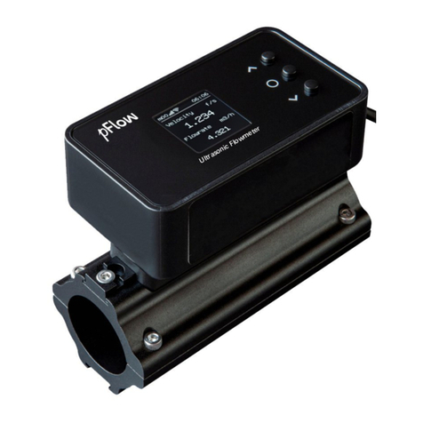
PFlow Industries D116 User manual

Version:3.0.0
Ultrasonic Flowm
Mo
Update
Record
D116
SeriesUltrason
wmeter Instruction
M
anu
Model:
D116
Revision 3.0.3
Date 09 . 2019
sonicFlowmeter
anual

Revision:3.0.3
Notice:
Thisinstruction manualisappropriate for
D1
Thisultrasonic flowmeter
adoptsARM.FPGA
Thisinstruction manualcontainsimportan
flowmeter
,avoiding damaging flowmeterand
Thisinstruction manualwill introduce
how
installation, wiring, quick setup
etc. to make
Understanding moreaboutthe menu settings
function option and outputfunction.
Warning
Maycause injury.
Attention
Maydamage the flowmeter
Someofthe instructionsmaybe
differen
requirements,otherwise, t
hereisno indica
instructions, please referto the version numbe
D116
SeriesUltrason
D116
seriesultrasonic flowmeter.
GA
chip and low-voltage wide-
pulse sending technolog
rtantinformation. Pleaseread carefullybeforethe ope
and improperuse.
howtousetheflowmeterstep
-by-step, including p
rod
ake it easierto operate.
ngscan fulfill yourhigherrequirementswiththe flowme
ter
.
renttothe flowmeters you purchased, dependingo
ndication
aboutthe productdesign and upgrade requ
mber, aswell asthe appendix.
sonicFlowmeter
Page2of53
logy.
operation ofthe
roduc
tcomponent,
meters
powerful
onconfiguration
equirement
inthe

Revision:3.0.3
Product Component
Inspection shouldbe made beforeinstalling
the packing list.Make surethatthere
isno da
damage thatmayhaveoccurred during trans
aspossible.
Transmitter
Accessories
MODEL:D11 6
DigitalCorrelation Transit-Time Flowmeter
Installaccessory
Coupling com
PipeStraps
D116
SeriesUltrason
ponent
s
ng the Flowmeter.Check toseeif the spareparts arein
no damage totheenclosuredue toaloosescreworloos
ansportation. Anyquestions,pleasecontactyourrepres
Transducers
Documents
ompound
1.InstructionManual
2.Packing List
3.Position drawing
sonicFlowmeter
Page3of53
inaccordance with
oosewire, orother
resentativeassoon

Revision:3.0.3
1
Transmitter Installationand Con
1.1 Inspectionprior to
Transmitter Installati
1.2 WireConnecting
................................
1.2.1 Power supplyoption
................................
1.2.2 Transmitter Wiring
................................
1.2.3 LengthenedCable Method
................................
1.3 Powering on................................
................................
1.4 KeypadFunctions
................................
1.5 KeypadOperation
................................
1.6 Flowmeter WindowDescriptions
................................
2
PipeParameter EntryShortcuts
2.1
Dual functionkeysmenudescription
2.2 Examples................................
................................
3MeasurementSite Selection
................................
4Transducer Installation
................................
4.1 Installingthetransducers
................................
4.1.1 Transducer Spacing
................................
4.1.2
Transducer Mounting Methods
4.1.3 VMethod ................................
................................
4.1.4 ZMethod ................................
................................
4.1.5
NMethod (notcommonlyused)
4.2 Transducer Mounting Inspection
................................
4.2.1 Signal Strength
................................
4.2.2 Signal Quality(Qvalue)
................................
4.2.3 Total TimeandDelta Time
................................
4.2.4 Transit TimeRatio
................................
4.2.5 Warnings................................
................................
5Operating Instructions
................................
5.1 SystemNormal Identification
................................
5.2 Zero Set Calibration
................................
5.3 Scale Factor................................
................................
5.4 SystemLock................................
................................
5.5 FrequencyOutput
................................
5.6
4~20mACurrentLoop OutputVerif
5.7 Recover theFactoryDefault
................................
5.8
4~20mAAnalogOutputCalibration
5.9 ESN ................................
................................
6Windows Display Explanations
................................
D116
SeriesUltrason
Content
onnection
................................
................................
tallation
................................................................
................................
................................
................................................................
................................
................................
................................................................
................................
................................
................................................................
................................
................................
................................
................................
................................
................................
................................
................................
................................................................
................................
................................
................................................................
................................
................................
................................
................................
ts
................................................................
.............................
tion
................................................................
................................
................................
................................................................
..........................
................................
................................
................................
................................
................................
................................
................................
................................................................
................................
................................
................................................................
................................
ds
................................................................
................................
................................
................................
................................
................................
................................
................................
ed)
................................................................
................................
................................
................................
................................
................................
................................................................
................................
................................
................................................................
..........................
................................
................................
................................
................................
................................................................
................................
................................
................................
................................
................................
................................
................................
................................
................................................................
..........................
................................
................................................................
................................
................................
................................
................................
................................
................................
................................
................................
................................................................
................................
rification(Optional)
................................
................................
................................
................................................................
............................
on
................................................................
................................
................................
................................................................
................................
................................
................................
...............................
sonicFlowmeter
Page4of53
................................
.................6
................................
........6
................................
................7
................................
..7
................................
....7
................................
.........................7
................................
.......................9
................................
...............9
................................
..............9
................................
.....................10
.............................
11
................................
...............11
..........................
12
................................
.....14
................................
............15
................................
..15
................................
..15
................................
................15
................................
.................15
................................
.................16
................................
..............16
................................
......................16
................................
.........16
..........................
17
................................
......................17
................................
...17
................................
..................17
................................
.............19
..........................
19
................................
.........19
................................
......................19
................................
.....................19
................................
.............20
................................
...................20
............................
20
................................
................21
................................
..21
...............................
22

Revision:3.0.3
6.1 WindowsDisplayCodes
................................
6.2 DisplayExplanation
................................
7ErrorDiagnoses
................................
7.1 Table1. Error codesandsolutions
................................
7.2
FrequentlyAskedQuestionsandAns
8Product Overview
................................
8.1 Introduction................................
................................
8.2 FeaturesofD116
................................
8.3 Specifications................................
................................
9Appendix1-
SerialInterface Netw
9.1 Overview................................
................................
9.2 Direct connectionvia RS-
485 tothe
9.3
Communicationprotocolandtheuse
9.3.1 FUJI Protocol
................................
9.3.2
MODBUS CommunicationPro
10 Appendix2-
W211 InsertionTran
10.1 Overview................................
................................
10.2 MeasurementPointSelection
................................
10.3
Determining Transducer Spacing &T
10.4 Transducer Mounting Methods
................................
10.4.1 ZMountingMethod
................................
10.4.2
PipeParameter EntryShortcuts
11 Appendix3-RTDModulea
nd PT
11.1 RTDEnergyMeter Function
................................
11.2 Wiring(PT1000)
................................
11.3 EnergyMeasurementMethods
................................
11.4 TemperatureCalibrationMethods
................................
11.5 InstallationofRTDModule
................................
____________________________________
____________________________________
____________________________________
D116
SeriesUltrason
................................
................................................................
................................
................................
................................................................
................................
................................
................................................................
.........................
................................
................................
................................
nswers
................................................................
................................
................................
................................................................
.....................
................................
................................
................................
................................
................................................................
................................
................................
................................
................................
etworkUseand Communications Protocol
..........................
................................
................................................................
..........................
hehostdevice
................................................................
.............................
use
................................................................
................................
................................
................................................................
................................
rotocol
................................................................
................................
ansducer
................................
................................
................................
................................................................
..........................
................................
................................................................
...........................
&Transducer Installation
................................
................................
................................
................................................................
........................
................................
................................................................
................................
uts
................................................................
................................
PT1000 Wiring (Moduleoptional)
................................
................................
................................................................
............................
................................
................................................................
................................
................................
................................................................
.........................
................................
................................
................................
................................
................................................................
.............................
Update Information:
______________________________________________
______________________________________________
______________________________________________
sonicFlowmeter
Page5of53
................................
..22
................................
.........23
.........................
37
................................
....................37
................................
.......38
.....................
39
................................
......................39
................................
..............39
................................
...................40
..........................
41
..........................
41
.............................
41
................................
...............41
................................
...........42
................................
.......43
................................
.................47
..........................
47
...........................
47
................................
...........47
........................
49
................................
.49
................................
...............49
................................
........51
............................
51
................................
...............51
.........................
51
................................
....................51
.............................
53
_______________
_______________
_______________

Revision:3.0.3
1
TransmitterInstallation and
1.1 Inspection
prior toTransm
Youwill find a"Position Drawing"
inthe
Please
useit asatemplateinthe place tha
going toinstall the Flowmeter.Then drill 4
holesatthe screwsposition shownon
thedr
the 5.0mm drill.
Take outthe enclosedscrewsand plastic
Insert
the plasticbushingsintothe installing
the flowmeterto the position and screw
it in.
Attention
When installing please ensure
D116
SeriesUltrason
nd Connection
nsmitterInstallation
the packing.
that
you are
rill 4installing
drawing with
sticbushings.
lling holes.Put
in.
ure the frontcover
issecure and will notfall open.
86mm
135mm
5.32lnch
3.39lnch
Positiondrawing
1.Placethistemplateonthewall and
holesof 5mmdiameter&40mm d
2.Insertaplastic bushing into eachof
holes.
3.Screw4pcsPA4 ×
30mm self tapp
screwsthroughthetransmitterenc
baseandattachitto thewall.
4.Tighten thescrewstosecureto the
enclosureon thewall.
MODELDCT1188
DigitalCorrelationTransit -Time
Flowmeter
135mm
5.32lnch
86mm
3.39lnch
MODEL:D116G
Digital CorrelationTransit-Time Flowmeter
sonicFlowmeter
Page6of53
nd drill 4
deep.
of the4
f tapping
nclosure
he
eter

Revision:3.0.3
1.2 WireConnecting
1.2.1 Power supplyoption
Customers should payspecialattention to spec
Factorystandard powersupplyis10~36VDC
To ensure the transmittercanwork normally, p
Ensure thatpowerconnectionsare made in acco
1.2.2 Transmitter Wiring
Once the electronicsenclosure hasbeeninsta
Openthe case, you
will find the transmitterin
Powersupply, Relayoutput,
OCTOutput,Up
interface.
Referto the belowdiagramforspecific connec
1.2.3 LengthenedCableMethod
Standard cable length ofsensoris
9 meters; i
fluid measurement.
Red Bushi
Flow
DC+DC- GE
DC 10-36V
Beingtested pi
UpstreamTransducer
OCT+
OCT
RL+RL-
RELAY
10~36VDC
D116
SeriesUltrason
specifythe desired powersupply
when wiring.
VDC/1Amax.
lly, please payattention to the followingswhen wiring:
n accordance with the specificationsshownon the transm
stalled, the Flowmeterwiring can be connected.
rinterfaceslabelsfromleftto rightasfollows:
Upstre
amtransducer,Downstreamtransducer, 4-
20mA
c connection:
rs; itcan be lengthened to
be 300 meters according to
the ac
ushing
EUP+UP- EDN+DN-
TRANSDUCER
I+I-
4-20mA
Blue Bushing
pipe
Black
Red
Shield
PipeStraps
DownstreamTransducer
+ OCT
-
OUT
Shield
Red
Black
Up-Stream
Down-Stream
Tx
RxGND
RS232(RS485)
AB
sonicFlowmeter
Page7of53
sm
itter.
A, RS485
he actualneed for
GND
485)

Revision:3.0.3
1.2.3.1
Sketch oflengthened Cable
1.2.3.2
Junction BoxRequiremen
The flowmeteruse
sealed waterproofjunction box
specificationsofthe junctionbox is
115 90
1.2.3.3 CableSpecifications
Name:Shielded Twisted Pair
AdministerStandard:JB8734.5-1998
Diameter: Φ5 mm
TwistLine Space:50 mm
Multi Core Line:0.4 mm2/radix
Wire Guage:AWG20#
Core Line Color: Red and Black
Shield Floor: 128 Intwine
Warning
Wire with poweroff. The
flow
D116
SeriesUltrason
able
ents
tion box,
installing 6 2press-connections, the r
ecommended
90 55mm.
wmeter
mustbe reliable grounding before installation.
sonicFlowmeter
Page8of53
ended minimum

Revision:3.0.3
1.3 Poweringon
Assoon asthe Flowmeterisswitched on, the
errorcode will displayon the screen (Refe
automaticallyaccording to the lastinputpara
Ifthe installation isaccomplished when syste
AfterS1, S2,S3, S4aredisplayed on the uppe
measurementcondition automatically.It isind
Ifit isthe fir
sttimetouseorinstall on anew
The systemwill default to the lastwindowse
1.4 KeypadFunctions
Thiskeypad isdualfunction keypad:
1. When separatelypressed, isshortcut
referring to "2. Quicklysetmenu
instructions
2. Press
and Numberkey,isM
referring to"6.Menu WindowDescription".
Followtheseguidelineswhen usingtheF
keypad (Referto Keypad Figure):
~ And To inputnumbers.
Backspace ordelete characters to the le
And
Returntothe lastmenu o
the nextmenu. Actsas"+"and "-"
functi
entering numbers.
1.5 KeypadOperation
The flowmeteradoptsthe windowsoftware
instrumentsetup and measurementresult di
inputparameters,modifysettingsordisplay
arearranged by2-
digitserialnumbers (includ
number,orso-called windowID
code,hasa
inputforpipe outside diameter,whileWindo
(Refer –
WindowsDisplay Explanations).
The keypad shortcuttovisi
ta specific windo
IDcode. Forexample, toinputorcheck the
IDcode 11.
Anothermethod tovisit aparticularwindow
the currentwindowIDcode isM02, press
WindowM00;then,press the
keyto
M02.
Win
dowsareseparated intothree types:(1)
PureDisplayType, such asM01, M00.
Youcancheckthe correspondingparamete
parameters, inputthe digitsand press
Menu
0 9 ●
<
^
^
^
Enter
D116
SeriesUltrason
on, the self
-
diagnosisprogramwill start torun. Ifanyerro
efer
-ErrorDiagnoses).Afterthatself-
diagnosis,the
parameters.
stemisswitched on, gain adjustmentcan be mo
nitored i
he upperleft cornerofthe screen, the systemwill acti
indicated bycode
"*R"
on the upperleft cornerofthe s
newsite, the customerneed toinputthe newinstallation
settingsand automaticallydisplaythe
m
atnextpowero
cutfunction,
ons
";
Menu key,
Flowmeter
he left.
ortoopen
unctionswhen
Selectamenu.Press thiskey
menu numbers and thenenterthe selec
example, toinputapipe outside diam
keys,where"11"
isthe
displaythe parameterforpipe outside d
aredesign toconsolidateorsubdivide all ofthe parame
displaysintomorethan 100 independentwindows.T
aymeasurementresultsby"visiting"aspecificwindow.
ncluding "+"sign)from00~99, then to+0, +1, etc. Each
a definedmeaning. Forexample, WindowM11 indicat
ndowM25 indicatesthe mounting spacing between the
s).
ndowisto pressthe
keyatanytime, then inputthe 2
he pipe outside diameter,justpress the
k
ndowistopress
and
keystoscroll the screen.
keytoenterWindowM01, press the
button
toback WindowM01, and pressthe
keyagainto
(1)DataType,such asM11, M12;(2)Option Type, such
eters byvisiting theDataType Windows.Ifyou wan
orpress first, inputthe digitsthen press
aga
Menu
1 1
Menu
Menu 1 1
^
^
^ ^
^
Enter Enter
sonicFlowmeter
Page9of53
rrorisdetected, a
n
he systemwillrun
ed in WindowM01.
activatethe normal
he screen.
on site
parameters.
ron.
yfir
st,inputtwo
selected menu. For
ameter,press
he windowIDto
de diameter.
meters entered, the
.The operatorca
n
w.Thesewindows
ach windowserial
catesthe parameter
he transducers,etc.
the 2
-digitwindow
keysforwindow
een. Forexample, if
tton againtoenter
ntoenterWindow
pe, such asM14;(3)
anttom
odifythe
again to confirm.
Menu

Revision:3.0.3
Example1:Toenterapipe
outside diamete
procedure isasfollows:
Press
keystoenterWi
numericalvalue displayed currentlyisaprev
press key.The symbol">"
and the fl
displayed atthe left end ofthe second
line on
inputthe parameters; ordo notpress the
.
You cancheckthe selected option byvisiti
Windows.Ifyou wanttomodifyit,you mus
the symbol">"
and the flashing cursorared
ofthe Screen. Operatorcanusethe
and
the screen and getthe required value then
confirm;orenterthe correspondingvalue op
press to confirm.
Forexample, if
the pipe materialis"Stain
toenterWindowM14, press
the options.Selectthe "1. Stainless Steel"op
and , then press
toconfirm
possibletopress
keytochange thes
until "1.Stainless Steel"isdisplayed on the
screen, then press to confirm.
Attention
Generally,press
keyfirst
possibleeven afterpressingt
"Unlock"it, select"Unlock"
in W
1.6
FlowmeterWindowDescripti
These windowsareassigned asfollows:
01~08
FlowTotalizerDisplay:todispla
time, presentoperation andflowr
10~29
InitialParameterSetup:toenterp
transducermounting method
and
30~38 FlowUnitsOptions:
toselectthe
on/off and resettotalizers, etc.
40~49
Setup options:Scaling factor, syst
55~89 Inputand outputsetup:
dateand ti
90~98
Diagnoses:Signalstrengthand s
sound velocity(WindowM92),to
(WindowM94),etc.
+0~+5
Appendix:poweron/off time, totalw
Attention
The otherwindowsforhardw
Menu 1 1
Enter
Enter
219●234 5 Enter
^
Enter
Menu 14
^
^
Enter
1
Enter
Enter
D116
SeriesUltrason
eterof219.234, the
WindowM11 (the
reviousvalue).Now
he flashing cursorare
on theScreen.
Then
key,directlyenter
isiting Option T
ype
ustpress
first,
edisplayed atthe left
and
toscroll
then press
to
ue optiondirectlyand
ainless
Steel",Press
ress
tomodify
l"option bypressing
firmthe
selection;Itis
eselection
and wait
the second line of
the
irstifoperatorwantstoenter
"modify"status.Ifthe "
mod
gthe
key,itmeansthatsystemislocked by
in WindowM47 and enterthe originalpassword.
criptions
playflowrate, positivetotal,negativetotal,nettotal,
wresultstoday, etc.
rpipe outside diameter,pipe wall thickness,fluidtype,
and spacing, etc.
the flowunit such ascubic
meter,literorother
units,can
ystemlo
ck (WindowM47), etc.
and time, ESN,communication baud rate setting, etc.
and signalquality(WindowM90),TOM/TOS*100 (Windo
,totaltimeand
deltatime(WindowM93),Reynoldsnu
lworking hours, on/off timesand a single
-
accuracyfunc
rdware adjustment
are reservedbythe manufacturer.
ter
Pip e OuterDiame
>_
Enter
^
Enter
Enter
Pip e Material
>
1.Stainle s sSte e l
Enter
sonicFlowmeter
Page10of53
modify
"isstill not
yapassword. To
l,velocity,date&
pe,
transducertype,
can
turntotalizers
indowM91),flow
numberand factor
unction calculator.
ame te r
[ 14
te e l

Revision:3.0.3
2
PipeParameterEntryShortc
2.1
Dualfunction keysmenu d
Press key
DisplayNetFlowToday/FlowMax /Flow
Average/CurrentRate in turn.
Press key
DisplayDayTotalizer
Flow/MonthlyTotali
/YearlyTotalizerFlowin turn.
Press key
DisplayTotalizerStart and Stop in turn.
Press key
Displayinstantaneouscoolcapacityand
cool
totalizer.
Press key
Displayinstantaneousheatcapacityand heat
totalizer.
Press key
Displaythe t
emp in, outand temperature diff
Press key
DisplayFlowRate and Velocity.
Press key
DisplayFlowSound Velocity.
Press key
DisplaySignalStrength and SignalQuality.
D116
SeriesUltrason
hortcuts
nu description
wMin/The
talizerFlow
cool
capacity
heatcapacity
ifference
.
FlowMax.
360 .000 0 m3
DayTotalize r
700.1000m3
6 0 sec
ON10.123m3
EFR0.0000GJ/
ENT0 X1
EFR0.0000 GJ /h
EPT0X1
In-Out- DeltaC
6.218.21-
2
Flow0.112 9 m3/h* R
Ve l 1.0415m/ s
Flu idSoundVe loc
0.0000m/ s
Strength+Quality
UP:00.0 DN:0 0.0Q
sonicFlowmeter
Page11of53
3/ h
m3
m3
J/h* R
GJ
/h* R
GJ
2.0 0
* R
cit y
ity[9 0
Q=0 0

Revision:3.0.3
Press key
Press Enttostart ManualTotalizer,then pre
end ManualTotalizer,press Enttoinput
TotalizertogetthefinalKfactor.Comp
calibration with pressing Entto store.
Press key
InputCode 1234 to complete ResetZero.
Press key
DisplaySystemErrorCodes.
2.2 Examples
Forexample, measuring the diameterof2
19
PipeMaterialiscarbon steel,No Liner,
can be
Step1. Pipe outside diameter:
Press
keystoente
M11, and enterthe pipe outside dia
then press the keyto confirm.
Step2. Pipe wall thickness
Press the
keytoente
M12, and enterthe pipe wall thickne
press the keyto confirm.
Step3. Pipe Material
Press the
keystoente
M14, press the key,press
the
keytoselectPipe
Material,an
keyto confirm.
Step4. Transducertype
(The transmitterisavailablefo
transducertypes.)
Press the
keytoente
M23,press the
key,movethe
keytoselecttransducertype,and
keyto confirm.
Menu 1 1
Enter
Menu 12
Enter
Menu 14
Enter
^
Enter
Menu 2 3
Enter
^
Enter
D116
SeriesUltrason
press Entto
nputStandard
mpletethe
19
mmand pipe wall thickness of6mm,
measuring mediu
can be operated asfollows
:
enterWindow
diameter,and
enterWindow
hickness,and
enterWindow
the
or
andpress th
e
forvarious
enterWindow
the
or
e,and press the
ManualCa lib r at e
PressEn t
Wh enRe a
SetZer o
PleaseEnterPW
*R-------- -
Syste m Norma l
PipeOuterDiame
219
Pip e WallT h ic k ne s s
6
mm
^
Pip e Mate r ial
0 . Ca r bonSteel
^
Tr ansduce r Type
0 . Standa r d
sonicFlowmeter
Page12of53
ediumiswater,
Read y
ete r
mm
e s s
mm
[ 14
pe[ 23

Revision:3.0.3
Step5. Transducermounting methods
Press the
keytoente
M24, press the key,press
the
keytoselecttransducer
method, and press the key
to con
Step6. AdjustTransducerspacing
Press the
keytoente
M25, accuratelyinstall the transduce
tothe displayed transducermounting
and the selected mountingmethod
Installing the Transducers inthischap
Step7. Displaymeasurementresult
Press the
keystoente
M01 todisplaymeasurementresult
the actualmeasurement)
Menu 2 4
Enter
^
Enter
Menu 2 5
Menu 0 1
D116
SeriesUltrason
enterWindow
the
or
cer
-mounting
o confirm
.
enterWindow
duceraccording
ounting spacing
hod (Referto
chapter).
enterWindow
ult.(
Baseon
^
Tr ansduce r Moun
0 . V
Trans d ucerSpa c
177.01mm
Flow0 .1129 m3 /h
Ve l 1.0 4 15m/ s
sonicFlowmeter
Page13of53
unt i n g
a c in g
mm
* R

Revision:3.0.3
3
MeasurementSiteSelection
When selecting ameasurementsite, itisimpo
to guarantee a highlyaccurate measurement.
Choose a section ofpipe thatisalwaysfull o
full horizontalpipe.
Ensureenough straightpipelengthatleast
transducers installation.
Ensure thatthe pipe surface temperature atthe
Considerthe inside condition ofthe pipe care
excessive corrosion orscaling.
10D min
10D min
10D min
L
D
5D min
0.5D min
P
Straightlengt
pip
Name
Pump
Value
Diffuser
Tee
90obend
Reducer
Flowcontrol
Chec
D116
SeriesUltrason
Selection
mportanttoselectan area wherethe fluidflowprofileis
ent. Use the following guidelinesto selecta properinstall
ll ofliquid, such asaverticalpipe withflowinthe upwa
stequaltothe figureshownbelowfortheupstreamand
tthe measuring pointiswithin the transducertemperatur
arefully.Ifpossible, selecta section ofpipewhere the in
L ≥10D
L ≥5D
L ≥50D
L ≥10D
L
≥30D
D
L≥5D
L≥10D L ≥5D
L≥50D
P
L≥30D L≥10D
gthofUpstrea
m
piping
Straightlengthof Downstre
piping
Detector
Flowcontrolleddownstream
trolledupstream
CheckValue
eckValue
sonicFlowmeter
Page14of53
isfully
developed
tallation site:
warddirection ora
and downstream
ture limits.
he inside isfree of
stream
am

Revision:3.0.3
4TransducerInstallation
4.1 Installingthetransducers
Before installing the transduce
rs, clean the pi
scale orloose paintand make a smooth surface.
transducers.Applya wide ban
d ofsonic coup
well ason the pipe surface,
ensure there are n
attach the transducers to the pipe with the strap
Note:
The
two transducers shouldbe mounted atthe p
Make sure thatthe transducermounting direc
During the installation, thereshould be no air
horizontalpipes, the transducers should bem
orderto avoid anyair bubblesinside the top po
transducers cannot
be mounted horizontallys
maybe necessarytomountthe transducers at
alwaysfull ofliquid).
4.1.1 Transducer Spacing
Afterentering the required parameters, the spac
standard transducerspacing (Referto Top Vi
WindowM25and space the transduce
rs acco
4.1.2
Transducer Mounting Meth
Three
transducermounting methodsare avail
Vmethod isprimarilyused on small diamete
appli
cationswhere the Vmethod cannotwor
generallyworksbetteron largerdiameterpipe
The Nmethod isan uncommonlyused method.
4.1.3 VMethod
The Vmethod isconsidered asthe standard m
diameters ranging from25mmto 400mm(1
"
requiresproperinstallation ofthe transducer
eitherside ofthe centerline.
DownstreamTransducer
UpstreamTransducer
Flow
SideView
D116
SeriesUltrason
he pipe surface where the transducers are to be mounted. R
rface. Choose asection ofsound conductingpipe forins
oupling compound down
thecenterofthe face ofeach tr
e no air bubblesbetween the transducers and the pipe w
strapsprovided and tighten themsecurely.
the pipe’scenterline on horizontalpipes.
irection isparallelwith the flow.
no air bubblesorparticlesbetween the transducerand the
mounted in the 3 o’clock and 9o’clock positionsofthe p
op portion ofthe pipe. (Referto TransducerMounting). I
llysymmetricallydue to limitation ofthe localinstallation cond
rs ata location where there isa guarantee
d
full pipe cond
he spacing between the ENDSofthe two transducers iscon
Viewon transducermounting methods). Check the data
accordingly.
thods
ailable. Theyare respectively:Vmethod, Zmethod
and
eterpipes(DN100
~300mm, 4〞~12〞
).TheZmethod i
ork due topoorsignalorno signaldetected. In addition,
pipes(overDN300mm, 12
〞)orcastiron pipes.
thod.
Itisused on sma
llerdiameterpipes(belowDN50mm
d method. Itusuallygivesa more accurate reading and i
"
~16〞
)approximately. Also, it isconvenientto use, but
ducer
s
, contacton the pipe atthe pipe’scenterline and equa
er
Transducer
Flow
TopViewSection
PipeStrap
Transducer
sonicFlowmeter
Page15of53
ed. Remove anyrust,
installing the
each transduceras
pe wall,
and then
pipe wall. On
the pipe section in
). Ifthe
tion conditions, it
pe condition (the pipe is
consideredasthe
he datadisplayed in
and
Nmethod. The
hod isused in
on, the Zmethod
50mm, 2
〞).
d isused on pipe
se, but
still
qualspacing on
cerSpace

Revision:3.0.3
4.1.4 ZMethod
The signaltransmitted in a Zmethod installa
when the pipesaretoo large,there are some s
Thisisbecausethe Zmethod utilizesa direct
liquid onlyonce.
The Zmethod isable to measure on pipe diam
Therefore, we recommend the Zmethod forp
4.1.5
NMethod(not commonlyus
With the Nmethod, the sound wavestraverse
suitable forsmallpipe diametermeasuremen
The measurementaccuracycan be improved
used).
4.2
TransducerMounting Inspec
Checkto see if the transducerisinstalled prope
to ensure properoperation and high reliabilit
signalstrength, totaltransit time, delta time a
The "mounting"
condition directlyinfluences
mostinstances, onlyapplya wide ban
d ofson
stick it to the outside pipe wall to getgood m
be carried outin orderto ensure the high reliab
4.2.1 SignalStrength
Signalstrength (displayed inWindowM90)
downstreamdirections. The relevantsignalstr
signaldetected while 99.9 represents
maximu
Normally, the strongerthe signalstrength det
the more stable the measurementvalue obtained.
Adjustthe transducerto the bestposition and c
adequatelyduring installation in orderto obta
DownstreamTransducer
UpstreamTransducer
Flow
SideView
DownstreamTransducer
UpstreamTransducer
Flow
SideView
D116
SeriesUltrason
llation hasless
attenuation than a signaltransmitted with
e suspended solid in the fluid, orthe
scaling
and linerar
ectlytransmitted (ratherthan reflected)
signalwhich tran
iameters ranging from100mmto
800mm(4〞~32〞
)app
orpipe diametersover300mm(12
〞).
yused)
rse the fluid
three timesand bounce twice
offthe pipe w
ent.
ed byextending the transit distance with the Nmethod (
nspection
roperlyand if there isan accurate and strong enough ultr
ilityofthe transducer. Itcan be confirmed by chec
king t
e aswell astransit time ratio.
uencesthe flowvalue accuracyand systemlong
-
time running
son
ic coupling compound lengthwise on theface ofthe
good measurementresults. However, the following inspection
eliabilityofthemeasurement
and long-
termoperation of
0)indicatesa detected strength ofthe signalboth fromup
lstrength isindicated bynumbers from00.0
~99
.9. 00.0
imumsignalstrength.
h detected, the longerthe operation ofthe instrumentreliab
tained.
on and check to ensure thatenough sonic coupling compound
o obtain themaximumsignalstrength.
er
Transducer
Flow
TopViewSection
PipeStrap
Transducer
er
Transducer
Flow
TopViewSection
PipeStrap
Transducer
sonicFlowmeter
Page16of53
with the Vmethod
rare too thick
.
transversesthe
)approximately.
pe walls. Itis
hod (uncommo
nly
gh ultrasonic signal
ng the detected
unning reliability.In
he transducerand
tionsstill need to
on ofthe instrument.
upstreamand
0.0 representsno
liably, aswell as
pound isapplied
cerSpacing
erSpacing

Revision:3.0.3
Systemnormallyrequiressignalstrength ove
directions. Ifthe signalstrength detected istoo
mounting spacing should bere-
adjusted and t
method to be Zmethod.
4.2.2 SignalQuality(Qvalue)
Qvalue isshort forSignalQuality(displayed
value isindicated bynumbersfrom00~99
. 0
maximum.
Normally, the transducerposition should be ad
checkedfrequentlyuntil the signalqualityde
4.2.3
TotalTimeand DeltaTime
"TotalTime and Delta Time"
, which displays
measurementcalculationsin the Flowmetera
fluctuateswidely, the flowand velocit
iesfluc
poor. Itmaybe the resulted ofpoorpipe-
inst
parameterinput.
Generally, "Delta Time"
fluctuation should be
velocityistoo lowcan the fluctuation be wide
4.2.4 TransitTimeRatio
Transit Time Ratio indicatesif the transducer
be 100+/-
3 if the installation isproper. Check
4.2.5 Warnings
(1)
Pipeparameters entered mustbe accu
(2) D
uring the installation, applyenough c
pipe wall. While checking the signa
mounting site until the strongest
largerthe pipe diameter, the mor
(3)
Checkto be sure the mounting s
transducerismounted atthe pipe’
(4)
Payspecialattention to those pipe
alwaysirregular.Ifthe signalstr
detected. Thus, it isnecessaryto check
been entered accurately.Check t
the pipe isnotworn-
out, andthe
the transducerisnottoo
close to a
etc. With the exception ofthese
to be changed.
Attention
Ifthe transittime ratio isove
(1)
Ifthe parameters (pipe ou
been enteredcorrectly,
(2)
Ifthe transducermounti
(3)
Ifthe transducerismoun
Ifthe scale istoo thick orthe p
D116
SeriesUltrason
ver6
0.0, whichisdetected fromboth upstreamand dow
stoo low, the transducerinstallation position and the tran
ed and the pipe should be re
-inspected. Ifnecessar
y, change t
yed in WindowM90). Itindicatesthe levelofthe signalde
. 00
representsthe minimumsigna
ldetected while 99 rep
d be adjusted repeatedlyand coupling compound application
detected isasstrong aspossible.
me
aysin WindowM93, indicatesthe conditionofthe insta
rare based upon these two parameters. Therefore, when
fluctuate accordingly
, t
hismeansthatthe signalqualityde
nstallation conditions, inadequate transducerinstallation o
d be less than
±
20%.Onlywhen the pipe diameteristoo
wider.
ducermounting spacing isaccurate. Thenormaltransit tim
heck it in WindowM91.
be accurate;otherwise the Flowmeterwill notwork prope
enough coupling compoundsin orderto stick the transducer
e signalstrength and Qvalue, move th
e transducers
slowl
gestsignaland maximumQvalue can be obtained. Make
ore the transducer
sshouldbe moved.
ng spacing isaccordance with th
e displayin WindowM25 and
ipe’scenterline on the same diameter.
e pipesthatformed bysteelrolls(pipe with seams), since
strength isalwaysdi
splayed as0.00, thatmeansthere is
to check thatthe parameters (including all the pipe para
heck tobe surethe transducermounting method hasbeen s
the linerisnottoo thick. Make sure there isindeed fluid
e to a valve orelbow, and there are nottoo manyair bubb
se reasons, if there
isstill no signaldetected, the measure
ver100
±3,it isnecessaryto check:
pe outside diameter, wall thickness, pipe material, liner, e
ounting spacing isaccordance with the displayin Window
ounted atthe pipe’scenterline on the same diameter,
the pipe mounting isdistorted in shape, etc.
sonicFlowmeter
Page17of53
and downstream
transducer
, change the mounting
gnaldetected. Q
e 99 representthe
cation should be
stallation. The
hen
"DeltaTime"
ydetected istoo
on orincorrect
too smallor
time rat
io should
roperly.
sducer
sonto the
wlyaround the
ke sure thatthe
25 and the
nce such pipe is
e isno signal
pe parameters) have
been selected properly,
id in the pipe or
bblesin the fluid,
urementsite has
r, etc.)have
ndowM25,

Revision:3.0.3
(5)
Make sure thatthe Flowmeteris
strength displayed, the higherthe
higherthe reliabilityofthe flow
wavesorthe signaldetected istoo poo
capabilityforreliable operation
(6)
Afterthe installation iscomplete, po
D116
SeriesUltrason
isable to run properlywithhigh reliability. The stronge
the Qvalue reached. The longerthe Flowmeterrunsaccur
wratesdisplayed. Ifthere isinterference fromambiente
stoo poor, the flowvalue displayed isnotreliable;consequen
on is
reduced.
ete, poweron the instrumentand check the result accord
sonicFlowmeter
Page18of53
ongerthe signal
accur
ately, the
entelectromagnetic
consequently,the
ordingly.

Revision:3.0.3
5Operating Instructions
5.1 SystemNo
rmalIdentificati
Press the keys.Ifthe letter"
*R
Ifthe letter"G"
isdisplayed,it indicatesthat
meanssystemnormal. Onlywhen the adjustm
abnormal.
Letter"I"
indicatesno signalisbeing detected.
transducers are installed firmly, etc.
5.2 Zero SetCalibration
Once zero flowoccurs, a zero pointmayindi
value isnotequalto "0", thisvalue indicates
betterthe qualityis. Conversely, if the Zero i
Ifthe zero setpointisnotattrue zero flow, a
measurementcapacityis, thelargerthe meas
pointreduc
ed toa definite degree, ascompar
difference fromzero pointbe ignored.
Foran ultrasonicFlowmeter,the measuremen
necessaryto performa static
zero setcalibrati
Press WindowM42 to setthe Zero, press
cornerreducing to be "0". Ifthisiscarried ou
restore settings.
5.3 ScaleFactor
Scale factorrefers to the ratio between "
actua
and
is2.00, and it isindicated as1.98on the
bestscale factorconstantis1.
However, it isdifficult to keep the scale fa
cto
difference iscalled "consistency".
During operation, there still existspossible d
when used on differentpipes. Thus
, scale fac
thatresult fromapplication on differentpipes
calibration.
The scale factorcan be inputin W
5.4 SystemLock
Systemlock isreadable butnotmodifiable
to p
unauthorized personnel.
Press the keys,
if displays"U
long password, and then pressthe
key
Unlockit by
using the selected password onl
press the keyand
enterthe correctpass
Keep the password in mind orreco
rded in a s
Menu 0 8
En
Menu 4 7
Enter
Enter
D116
SeriesUltrason
cation
*R
"
displayson the screen, it indicatessystemnormal.
hatsystemisadjusting the signalgain priorto the measu
stmenttakestoo long withoutstopping, can
systembe iden
ected. Check thetransducerwiring connectionsare correc
ndicate on ea
chmeasuring instrument,
butthe displayed
es"Zero". To anymeasuring instrument, thesmallerthe
o istoo big, thatindicatesthe qualityo
fthe instrumenti
, a measurementdifference mayoccur. Thesmallerthe ph
easurementdifference fromthe zero pointwill exist. Onl
pared with the physicalmeasurementcapacity, can the m
entdifference fromzero pointcannotbe ignored atlow
ration to improve lowflowmeasurementaccuracy.
first, and then wait the readingsdisplayed atthe lo
ed outwith flow,the flowwill be displayed as"0", M43 can he
tual
value"and "reading value"
.Forexample, when the
he instrument, the scale factorreadingis2/1.98. Thismean
ctoras
"1"on the instrumentespeciallyin batch
producti
e difference inpipe parameters, etc. The
"scale factor"
m
factorcalibration isspeciallydesigned forcalibrating the d
pes. The scale factorentered mustbe one thatresultsfro
n WindowM45.
to preventoperation errordue to unauthorized tampering
"Unlock"on the screen, then
press the
key, enter
keyto confirm.
nly. Press
, if "lock"isdisplayed on the
s
password, then press
to confirm.
n a safe place
,otherwise the instrumentcannotbe used.
Enter
Enter
Menu 4 7
Enter
sonicFlowmeter
Page19of53
al.
surement. Also, it
be identified as
rrect, the
ed measuring
the "Zero"
is, the
tispoor.
he physical
nlywhen zero
he measuring
owflow. Itis
he lowerright
43 can help to
he measur
ement
meansthatthe
oductions
.The
maybe necessary
ng the differences
fromactual
ring by
er
6 numerically
screen
, then

Revision:3.0.3
5.5 Frequency Output
The Flowmeterisprovided with a frequencyou
displayed indicatesthe high orlowflowrate
ashisrequirements.
Forexample:if a pipe flowrange is0~3000
m
configuration isasfollows:
In WindowM68 (lowlimitfrequencyoutput
In WindowM69 (high limit frequencyoutpu
TypicalOCTOutputwiring diagramasbelow:
5.6 4~20mA CurrentLoop
Out
Processing a currentloop outputexceeding an
withmultiple outputmodessuch asflow
rate
"WindowsDisplayExplanations".
In WindowM56, entera 4mAflowrate
orflu
in WindowM57. Forexample, if the flowrange
1000 inWindowM57.
Calibrating and testing the currentloop isperf
Press , move or
readings, connectan ammeterto testthe curr
difference iswithin tolerance.
Ifthe difference
calibrate the currentloop.
Checkthe presentcurrentloop outputinWindo
5.7
RecovertheFactory Defau
Press
keysto Windowm
factorydefault.
RL1R
RELAY
Menu 5 8 Enter ^
Menu 37Enter
D116
SeriesUltrason
equencyoutputtransmitterfunction. The high orlowfrequenc
te reading. The usercan res
etthe frequency outputasw
m
3/h, the relative frequencyoutputrequired is0~5
000H
putflowvalue
),input0;
putflowvalue), input3000;
low:
OCTOutputWiring Diagram
utput
Verification(Optional)
g an
accuracyof
0.1%, the flowmeterisprogrammable and con
ate
orfluid velocity
. Selectin WindowM55.Fordetails, p
fluid velocity
value. Enterthe 20mAflowrate
orfluid v
range in a specific pipe is0
~1000m3
/h, enter0 in Windo
performed
in WindowM58. Complete the stepsasfollow
to display"0mA","4mA","8mA", "12mA","
16mA
he currentloop outputand calculate the difference. Calibrate
ence iswithouttolerance, referto the "
Analog Output
Ca
indowM59 asit changesalongwith change in flow.
fault
m37,
press or
keyto choose"Reset"keysto
OCT+OCT-
OCTOUT
COM
RL2
LAY
EUP+ UP-
TRANS
5~10K1/4w
Vcc
Sig
^
^
^
sonicFlowmeter
Page20of53
equencyoutput
well asflowrate
000Hz, and the
e and configurable
ils, please referto
id velocity
value
ndowM56 and
llows:
mA
", "20mA"
ate it if the
Calibration
"to
sto recoverthe
Other manuals for D116
1
Table of contents
Other PFlow Industries Measuring Instrument manuals

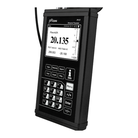
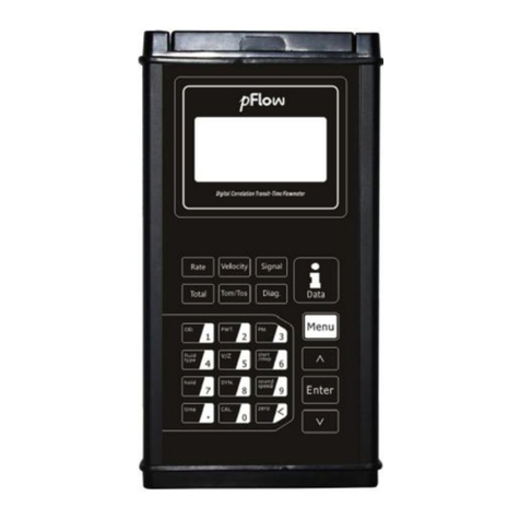
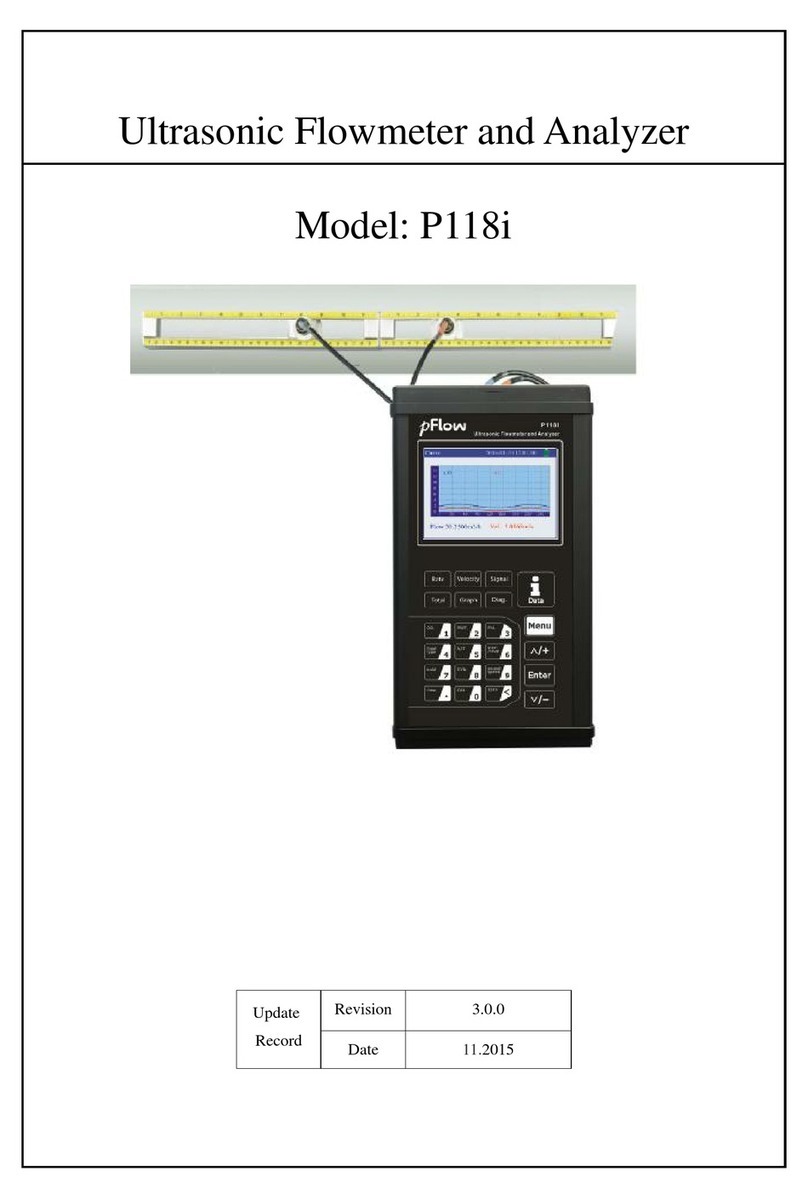
PFlow Industries
PFlow Industries P116 User manual

PFlow Industries
PFlow Industries P117 User manual

PFlow Industries
PFlow Industries D118 User manual

PFlow Industries
PFlow Industries P117 User manual

PFlow Industries
PFlow Industries D116 User manual

PFlow Industries
PFlow Industries P118i User manual

PFlow Industries
PFlow Industries P117 User manual

PFlow Industries
PFlow Industries F2 User manual