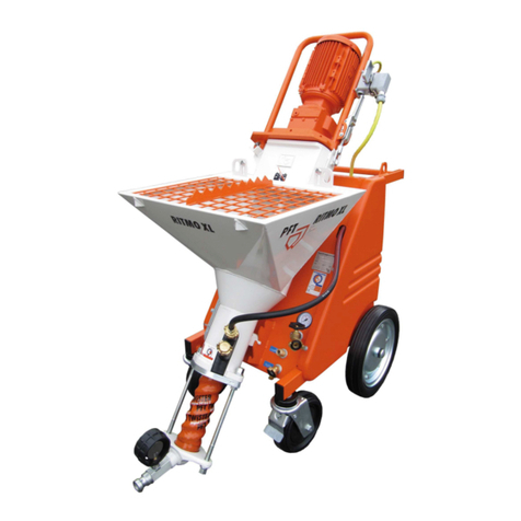
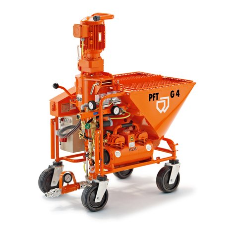
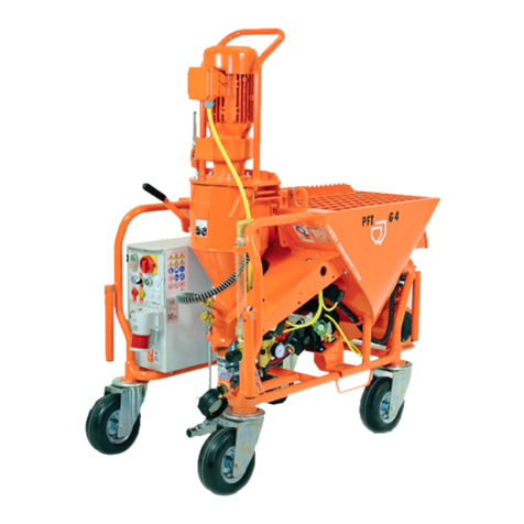
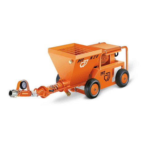
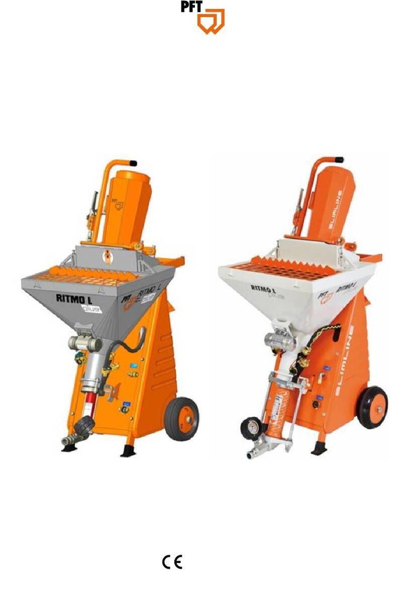
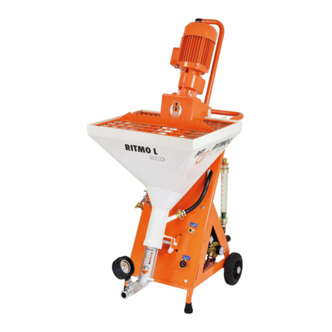
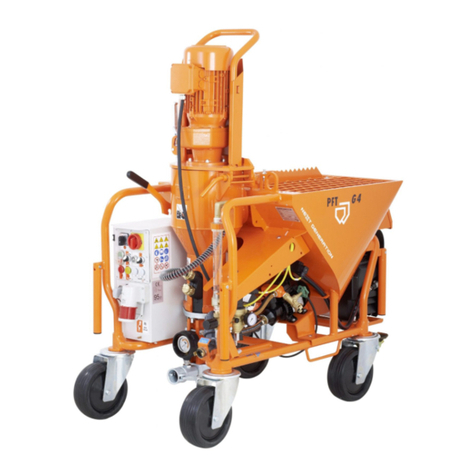
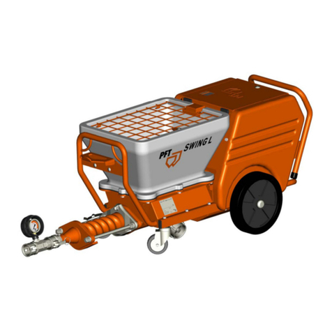
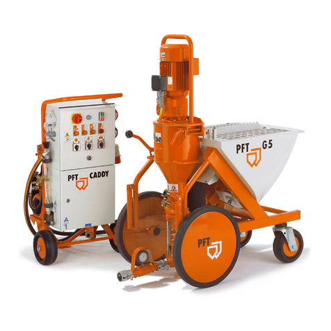
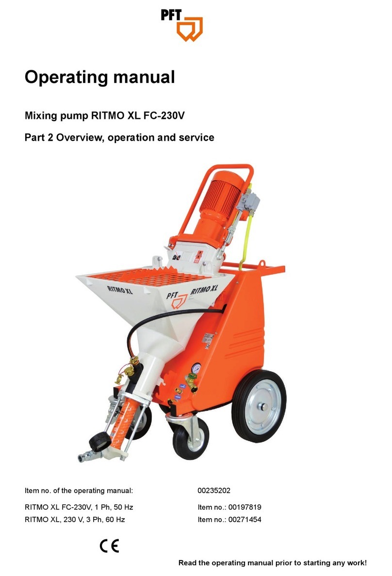
PFT G 5 c FU 230V User manual

OPERATING INSTRUCTIONS
BAL.NO.00 07 45 22
MIXING PUMP
PFT G 5 c FU 230V
WE KEEP THINGS MOVING

It is prohibited to forward this document, even excerpts, without written authorization by us. All technical
specifications, diagrams etc. are subject to copyright protection. All rights, errors and modifications reserved.
© by Knauf PFT GmbH & Co. KG

____________________________________________________________________________________________________________
PFT G 5 c FU 230 1
General Information 01.2005
____________________________________________________________________________________________________________
________________________________________________________________________________________
Knauf PFT GmbH & Co. KG Telephone 09323 / 31-760
PO Box 60 Telefax 09323 / 31-770
D-97343 Iphofen Internet www.pft.de
________________________________________________________________________________________
Dear PFT Customer,
Congratulations on your purchase. You have made a wise choice, because you appre-
ciate the quality of a brand from a company with a name that has exemplified quality.
The PFT G 5 c FU 230 mixing pump uses state-of-the-art technology. It was designed
in a task-optimized way so that it can be a trustworthy aid for rough construction site
conditions.
These operating instructions should always be stored and kept at hand at the
machine’s application site. They give you information on the various functions of the
system. Study the operating instructions thoroughly before starting the machine, as we
claim no responsibility for accidents or damage to the machine caused by incorrect
operation.
The PFT G 5 c FU 230 mixing pump will be a trustworthy aid, if it is operated correctly
and handled with care.
It is prohibited to forward this document, even excerpts, without written authorization by
us. All technical specifications, diagrams etc. are subject to copyright protection. All
rights, errors and modifications reserved.

____________________________________________________________________________________________________________
PFT G 5 c FU 230 2
General Information 01.2005
____________________________________________________________________________________________________________
________________________________________________________________________________________
Knauf PFT GmbH & Co. KG Telephone 09323 / 31-760
PO Box 60 Telefax 09323 / 31-770
D-97343 Iphofen Internet www.pft.de
________________________________________________________________________________________

____________________________________________________________________________________________________________
PFT G 5 c FU 230 3
PFT Sales Information 01.2005
____________________________________________________________________________________________________________
________________________________________________________________________________________
Knauf PFT GmbH & Co. KG Telephone 09323 / 31-760
PO Box 60 Telefax 09323 / 31-770
D-97343 Iphofen Internet www.pft.de
________________________________________________________________________________________
Initial inspection after delivery
An indispensable task of all technicians delivering the PFT G 5 c FU 230 mixing pump
is the inspection of the machine settings at the end of the first spraying phase. The
factory settings can be changed during the first operation. If these changes are not
corrected in time, immediately after initial start-up, then operating trouble can be
expected.
After putting the PFT G 5 c FU 230 mixing pump into service and giving appropriate
instructions, after about two hours, the technician must always carry out the following
checks / make the following settings:
1. Water safety switch
2. Pump pressure, backpressure
3. Pressure relief valve on compressor
4. Air nozzle tube clearance (spray pattern)
5. Air safety switch
6. Compressor safety switch
7. Remote control switch
8. Pressure reducer
9. Motor protection switch

____________________________________________________________________________________________________________
PFT G 5 c FU 230 4
Table of Contents 01.2005
____________________________________________________________________________________________________________
________________________________________________________________________________________
Knauf PFT GmbH & Co. KG Telephone 09323 / 31-760
PO Box 60 Telefax 09323 / 31-770
D-97343 Iphofen Internet www.pft.de
________________________________________________________________________________________
General information............................................................................................................................................1
PFT sales information.........................................................................................................................................3
Table of contents................................................................................................................................................4
Overview.............................................................................................................................................................5
Water manifold ...................................................................................................................................................6
Air manifold.........................................................................................................................................................7
Description of functions ......................................................................................................................................9
Basic safety instructions .................................................................................................................................. 10
Setting values ...................................................................................................................................................12
Mortar pump .....................................................................................................................................................13
Initial Start.........................................................................................................................................................15
Mortar consistency / spraying guns and nozzles / interruption of work.............................................................19
Measures at the end of work and when cleaning .............................................................................................20
Check list..........................................................................................................................................................22
Clearing hose blocks ........................................................................................................................................24
Maintenance .....................................................................................................................................................25
Accessories ......................................................................................................................................................27
Circuit diagrams................................................................................................................................................28
Spare part lists..................................................................................................................................................30
Technical data ..................................................................................................................................................44
____________________________________________________________________________________________________________
PFT G 5 c FU 230 5
Overview 01.2005
____________________________________________________________________________________________________________
________________________________________________________________________________________
Knauf PFT GmbH & Co. KG Telephone 09323 / 31-760
PO Box 60 Telefax 09323 / 31-770
D-97343 Iphofen Internet www.pft.de
________________________________________________________________________________________
1. Mixing pump motor 11.
Pump system D6-2L
2. Star wheel 12.
Water manifold
3. Protection grille with bag opener 13.
Water inlet
4. Material hopper 14.
Control box
5. Connecting cable high pressure pump 15.
Mixing tube with exchangeable flange
6. High pressure pump 16.
Locking lever
7. Frame 17.
Motor flange
8. Star wheel gearbox 18.
Snap lock
9. Compressor 19.
Motor connection cable
10.
Connection cable compressor

____________________________________________________________________________________________________________
PFT G 5 c FU 230 6
Water Manifold 01.2005
____________________________________________________________________________________________________________
________________________________________________________________________________________
Knauf PFT GmbH & Co. KG Telephone 09323 / 31-760
PO Box 60 Telefax 09323 / 31-770
D-97343 Iphofen Internet www.pft.de
________________________________________________________________________________________
1. Water to mixing tube 7. Outlet tap
2. Water intake valve 8. Needle valve
3. Water safety switch 9. Water flow meter
4. Water intake (high pressure pump) 10.
Gauge primary water pressure
5. Pressure reducer 11.
Gauge water operating pressure
6. Solenoid valve

____________________________________________________________________________________________________________
PFT G 5 c FU 230 7
Air Manifold 01.2005
____________________________________________________________________________________________________________
________________________________________________________________________________________
Knauf PFT GmbH & Co. KG Telephone 09323 / 31-760
PO Box 60 Telefax 09323 / 31-770
D-97343 Iphofen Internet www.pft.de
________________________________________________________________________________________
1. Socket compressor 230 V, 16 A 8. Motor mixer direction of rotation
2. Socket high pressure pump 230 V, 16 A 9. Water flow button
3. Housing 10-pin, mixer motor 10.
Operation ON
4. Main power supply CEE 3X16 A 11.
Operation OFF
5. Remote control socket 42 V 12.
Main switch
6. Blind plug for remote control socket 13.
Fault control lamp
7. Selector switch star wheel

____________________________________________________________________________________________________________
PFT G 5 c FU 230 8
Air Manifold 01.2005
____________________________________________________________________________________________________________
________________________________________________________________________________________
Knauf PFT GmbH & Co. KG Telephone 09323 / 31-760
PO Box 60 Telefax 09323 / 31-770
D-97343 Iphofen Internet www.pft.de
________________________________________________________________________________________
1. Air from compressor 4. Air pressure gauge
2. Counter flow valve 5. Air pressure safety switch
3. Air pressure safety switch 6. Air to the spraying gun

____________________________________________________________________________________________________________
PFT G 5 c FU 230 9
Description of Functions 01.2005
____________________________________________________________________________________________________________
________________________________________________________________________________________
Knauf PFT GmbH & Co. KG Telephone 09323 / 31-760
PO Box 60 Telefax 09323 / 31-770
D-97343 Iphofen Internet www.pft.de
________________________________________________________________________________________
The PFT G 5 c FU 230 mixing pump is a continuously operating mixing pump for pre-
mixed ready-to-use dry mortar. It can be filled either with bagged material or using the
delivery or injection hood.
Please observe the processing guidelines of the material manufacturer.
The machine consists of carryable single components of small, handy dimensions and
light weight that allow fast, convenient transport.
When operating the machine, the following aspects must be observed:
1. Connection worksite power - control box
2. Connection control box – pump motor
3. Connection control box – compressor
4. Connection compressor – air manifold
5. Connection water supply – water manifold / high pressure pump
6. Connection air manifold – air hose
7. Connection air hose – spraying gun
8. Connection mixing tube – mortar pressure gauge
9. Connection mortar pressure gauge – mortar hose
10. Connection mortar hose – spraying gun

________________________________________________________________________________________________
_______________
PFT G 5 c FU 230
10
Basic Safety Instructions
01.2005
________________________________________________________________________________________________
_______________
________________________________________________________________________________________
Knauf PFT GmbH & Co. KG Telephone 09323 / 31-760
PO Box 60 Telefax 09323 / 31-770
D-97343 Iphofen Internet www.pft.de
________________________________________________________________________________________
The following terms and symbols are used in this manual for particularly important information:
NOTE:
Special information for running the machine efficiently.
WARNING!
Special information, regulations and restrictions concerning the prevention of
damage.
WARNING!
The machine should only be used if it is in technically perfect condition and in
compliance with the regulations. Pay attention to safety and the operating instructions. It is especially
important to immediately rectify all faults which could impair safety. Proper machine operation includes
following the instructions in the operating manual and complying with the inspection and maintenance
conditions.
In order to make operating our machines as easy as possible for you, we would like to briefly inform
you of the most important safety regulations. If you comply with these regulations, you will be able to
use our machine in a safe and quality-assuring manner for a long time to come.

____________________________________________________________________________________________________________
PFT G 5 c FU 230 11
Basic Safety Instructions 01.2005
____________________________________________________________________________________________________________
________________________________________________________________________________________
Knauf PFT GmbH & Co. KG Telephone 09323 / 31-760
PO Box 60 Telefax 09323 / 31-770
D-97343 Iphofen Internet www.pft.de
________________________________________________________________________________________
1. Follow all safety instructions and danger warnings on the machine. Ensure that all
instructions are kept legible!
2. Inspect the machine for visible damage and defects at least once every shift! If you notice
any safety-threatening alterations to the machine or its operating behavior, stop the
machine immediately and notify your supervisor!
3. Do not attempt to modify the machine in any way which may impair its safety without first
consulting your machine dealer! This also applies to the installation of unchecked “safety
devices”!
4. All spare parts must comply with the technical requirements of the manufacturer. This is
guarantied for all original PFT parts!
5. Only trained or authorized personnel should operate the machine. Clearly define all lines
of responsibility for operation, equipping, service and maintenance!
6. Personnel undergoing training should only be allowed to operate the machine under the
supervision of experienced personnel!
7. All electrical work should be carried out by a qualified electrician or by trained personnel
under the supervision of a qualified electrician and should comply with electro-technical
regulations.
8. Observe all instructions for turning the machine on and off. Watch control lamps for
signals.
9. If the machine is completely switched off for maintenance and repair work, it must be
ensured that it cannot be switched back on accidentally (for example, lock the main switch
and remove the key, or attach a warning sign to the main switch).
10. Before cleaning the machine with a water jet, seal all openings through which water could
enter, thereby impairing the safety and proper functioning of the machine (electric motors
and control boxes). After cleaning, remove all covers.
11. Only use original fuses with prescribed amps!
12. Control box must be closed during operation!
13. Disconnect the machine from any external energy source before you relocate it, even if
you are only moving it a short distance. Prior to putting the machine back into service, it
should be connected to the mains correctly.
14. Set up the machine on stable and horizontal ground and secure it against unintentional
movements.
15. Lay out the conveying lines safely. Do not rest them on sharp edges!
16. Depressurize all conveying systems before opening conveying lines!
17. When unblocking hoses, stand away from the machine to avoid injury through high-
pressure discharges of mortar. Always wear safety goggles. No other persons should be
near the machine.
18. If the permanent noise level exceeds 85 dB(A), appropriate noise protection devices must
be provided.
19. If required, wear the following protective clothing while spraying: Safety goggles, safety
shoes, safety clothing, gloves, protective skin cream and respirator mask.
20. Have the machine inspected by a qualified person. This should however happen at least
once a year.

____________________________________________________________________________________________________________
PFT G 5 c FU 230 12
Setting Values:
ATTENTION! technical modification
01.2005
____________________________________________________________________________________________________________
________________________________________________________________________________________
Knauf PFT GmbH & Co. KG Telephone 09323 / 31-760
PO Box 60 Telefax 09323 / 31-770
D-97343 Iphofen Internet www.pft.de
________________________________________________________________________________________
Safety switch
Switching on the machine Switching off the machine
Water 2.2 bar 1.9 bar
Air 0.9 bar 1.2 bar
Compressor 2 bar 3 bar
Compressor safety valve
1.5 bar against closed air pipe (factory setting, secured)
Pressure reducing valve
1.9 bar for maximum flow at water manifold (1000 l/min)
Motor protection switch
Output Setting value Designation
Star wheel 0.37 kW 1.6 A Q2
Air nozzle tube gap
The gap between air nozzle tube and spray cap should always be equivalent to the
diameter of the spray cap;
e.g.: 14 mm spray cap = 14 mm gap.
Direction of rotation of the star wheel motor
The star wheel usually operates independent of the direction of rotation. If a SILOMAT
conveying system is being used, we recommend a clockwise direction of rotation
(factory setting). This ensures that the pump motor also runs in the correct direction.
Star wheel
Gap star wheel to hopper floor: Factory setting approx. 8 mm
Rule of thumb:
1.5 x diameter of largest dry mortar particle. If required, star wheel distance disk
(item no. 20 10 19 00) can be installed for coarse plaster.

____________________________________________________________________________________________________________
PFT G 5 c FU 230 13
Mortar Pump 01.2005
____________________________________________________________________________________________________________
________________________________________________________________________________________
Knauf PFT GmbH & Co. KG Telephone 09323 / 31-760
PO Box 60 Telefax 09323 / 31-770
D-97343 Iphofen Internet www.pft.de
________________________________________________________________________________________
The PFT G 5 c mixing pump is standard-equipped with a D6-2L pump system.
Rotor and stator are subject to wear and must be inspected on a regular basis.
WARNING!
The use of a mortar pressure gauge is absolutely imperative according to the safety
regulations of the Builder’s Guild.
PFT mortar pressure gauges monitor the mortar consistency efficiently and easily.
Some advantages of the mortar pressure gauge:
-Exact regulation of correct mortar consistency
-Constant monitoring of correct conveying pressure
-Early detection of clogging or overloading of pump motor
-Establishes zero pressure
-Contributes significantly to the safety of operating personnel
-Durability of pump components
PFT pump components
New pump components with a conveying hose of 10 m should attain a conveying
pressure of approx. 15 bar / 30 bar and maintain a backpressure of approx. 8 bar /
12 bar before and after the first spraying. We recommend using the PFT pressure
tester with coupling and outlet tap to monitor the backpressure
(item no. 20 21 68 10).
During installation/removal of the mortar pump, the following must be observed:
- the main switch must be switched off during assembly.
Furthermore observe that:
- a new rotor and stator must be run in; real pressure values can only be determined
after the first spraying.
- pump components which neither attain the required conveying pressure nor
maintain the required backpressure are worn out and must be replaced.
Checking the conveying pressure and backpressure
- Connect 10 m conveying hose
- Connect the pressure tester to outlet tap at end of the hose
- Open valve
- Switch on machine and let water run until water emerges from the outlet tap (let
hose bleed)

____________________________________________________________________________________________________________
PFT G 5 c FU 230 14
Mortar Pump 01.2005
____________________________________________________________________________________________________________
________________________________________________________________________________________
Knauf PFT GmbH & Co. KG Telephone 09323 / 31-760
PO Box 60 Telefax 09323 / 31-770
D-97343 Iphofen Internet www.pft.de
________________________________________________________________________________________
- Close valve
- Let pump run against pressure until there is no more increase in pressure
- Switch off the machine
- If the required pressure is no longer attained, the maintenance-free pump must be
replaced
-Check the backpressure
-A backpressure of approx. 14 bar should be maintained in the hose by the screw
pump (for TWISTER D5-2,5)
NOTE:
The test pressure with water should be 5 to 10 bar above the expected mortar
conveying pressure!
An adverse position of the screw pump in the liner will result in water flowing back to
the hopper accompanied by a distinct gurgling noise. Switch the machine on and off
repeatedly until you find the position in which the rotor seals with the stator.
NOTE!
1. Stator TWISTER D5-2,5 can be used up to 30 bar operating pressure.
2. The minimum conveying distance depends mainly on how the mortar flows.
Heavy, coarse-grained mortar does not flow easily. Fluid mortars, filling
compounds and floor screed flow easily.
3. Use thicker mortar hoses if you exceed an operating pressure of 30 bar.
4. To avoid machine breakdowns and excessive wear on pump motor, pump shaft
and pump, always use original spare parts
PFT rotors
PFT stators
PFT pump shafts
PFT mortar pressure hoses
PFT clamps.
These components are compatible with one another and form a single constructive
unit together with the machine. If you do not follow these recommendations, you will
not only lose your warranty rights, but the quality of the mortar you are producing will
also suffer.

____________________________________________________________________________________________________________
PFT G 5 c FU 230 15
Initial Start 01.2005
____________________________________________________________________________________________________________
________________________________________________________________________________________
Knauf PFT GmbH & Co. KG Telephone 09323 / 31-760
PO Box 60 Telefax 09323 / 31-770
D-97343 Iphofen Internet www.pft.de
________________________________________________________________________________________
- Transport assemblies as near as possible to the object to work with
(assembly see transport).
- Lock the castor before putting the machine into service.
- Connect water intake to ¾" hose. Open water intake to vent and clean the hose
line. Close water intake.
- Connect water hose to inlet of water manifold / water pump.
Close drainage valves on water manifold
- at a water pressure below 2.5 bar, the installed water pump can be used to
increase pressure.
WARNING!
When working using the water barrel, the suction inlet with filter screen
(item no. 20 47 50 00 ) must be mounted (bleed water pump).
The machine may only be connected to a 16 A worksite switchgear assembly with
approved 30 mA FI safety switch. The connection cable must be equivalent to the
H07 RN-F 3x2.5 mm
2
version.
We always recommend using the PFT power cable 3x2.5 mm², 25 m with earthling
plug and CEE coupling (item no. 20 42 34 20).
Before the cabinet box is powered, the following must be observed:
- Turn off main reversing switch (position “0”, lockable)
- Turn star wheel switch to “0” position
- Pull out blind plug
Connect pump motor (10-pin plug)
Switch off compressor (pull out plug)

____________________________________________________________________________________________________________
PFT G 5 c FU 230 16
Initial Start 01.2005
____________________________________________________________________________________________________________
________________________________________________________________________________________
Knauf PFT GmbH & Co. KG Telephone 09323 / 31-760
PO Box 60 Telefax 09323 / 31-770
D-97343 Iphofen Internet www.pft.de
________________________________________________________________________________________
Connect control box to power supply
Now the following steps must be carried out:
Turn on the main switch
Warning!
The protective grille must not be removed during operation or while preparing the
machine.
Press water flow button (1) (water pump runs), adjust estimated water quantity at the
needle valve (2).
Connect water hose of water flow meter to upper water inlet of the mixing tube.
Press water flow button briefly. On starting, there must be a sufficient quantity of
water in the mixing area so that the rotor head is covered (check for leaks, screw
pump might be defective).
Check water level (can be done with tilted pump motor).
1
2

____________________________________________________________________________________________________________
PFT G 5 c FU 230 17
Initial Start 01.2005
____________________________________________________________________________________________________________
________________________________________________________________________________________
Knauf PFT GmbH & Co. KG Telephone 09323 / 31-760
PO Box 60 Telefax 09323 / 31-770
D-97343 Iphofen Internet www.pft.de
________________________________________________________________________________________
WARNING!
If the 7-pin connection plug of the mixing pump motor is removed, the control circuit
is interrupted (starting lock). To put the machine back into service, the green OFF
switch must be used again.
Turn star wheel switch briefly to “Hand”. The star wheel can be switched to the
positions:
HAND
0
AUTOMATIC.
HAND
The star wheel always runs if the machine is connected and switched on. In this
position, mortar can be added to the mixing area, if the pump is not running. We call
this “Swamping”! For heavy or dispersion mortars we recommend “swamping” and
the brief opening of the mixing area’s lower water connection so that excess water
can be drained. (The control circuit must be interrupted by removing the blind plug).
IMPORTANT!
The TWISTER D 6-3 pump always requires swamping!
ZERO
Star wheel is switched off thus interrupting the supply of mortar to the mixing area.
E.g. when cleaning the mixing area with a mixing cleaner or when adjusting the
pump.
AUTOMATIC
Star wheel runs in synchronization with the mixing pump and is switched on and off
using the air control or remote control.
Connect the mortar pressure gauge to the pressure flange.
Fill the storage container with dry mortar.
Turn star wheel switch (1) to automatic. Pull out blind plug (2). The machine is now
running. The mortar consistency can now be checked at the mortar outlet flange (do
not yet connect mortar hose). While the motor is running, adjust the water quantity to
approx. 10 % above the reference value. The reference value is the water value for
the correct mortar consistency;
e.g.: Knauf MP 75 – reference value approx. 650 to 750 l/h
If mortar emerges, correct the water supply for optimum consistency by adjusting the
water quantity using the needle valve – visible at the cone of the water flow meter.
Turn the hand wheel in clockwise direction to reduce water flow. Turn it in the
opposite direction to increase water flow.
1
2

____________________________________________________________________________________________________________
PFT G 5 c FU 230 18
Initial Start 01.2005
____________________________________________________________________________________________________________
________________________________________________________________________________________
Knauf PFT GmbH & Co. KG Telephone 09323 / 31-760
PO Box 60 Telefax 09323 / 31-770
D-97343 Iphofen Internet www.pft.de
________________________________________________________________________________________
Operate red “OFF” pressure switch (machine stops)
Connect air hose to air manifold and spraying gun
Switch on compressor (insert plug)
Connect all required mortar hoses to each other and flush with water to avoid hose
blocks (do not leave water in hoses). To do so, use cleaner coupling (in tool bag).
If mortar quality is unknown, pour approx. 3 liters lime or plaster slurry into the first
hose after the machine.
WARNING!
Make sure that the coupling is clean and correctly joined.
Connect hoses to the mortar pressure gauge and again observe the mortar hose
seal.
Connect spraying gun (finishing coat gun or crimp valve gun) to mortar hose.
Press selector switch “ON” and open air tap on spraying gun. The machine starts;
cleaning can now be started.
At first, mortar of thin consistency emerges at the spraying gun, then mortar of the
correct consistency. If required, use the needle valve for making further adjustments.
Open and close the air tap on the spraying gun to switch the machine on and off.
Table of contents
Other PFT Water Pump manuals
Popular Water Pump manuals by other brands

EINHELL
EINHELL GC-GP 6040 ECO operating instructions

Graco
Graco BLUE DEVIL 260000 Instructions-parts list

AniOne
AniOne TP-180LV operating instructions

Berkeley
Berkeley 10PDH11VT Installation, Operation & Parts Manual

Jebao
Jebao PF-750 owner's manual

Samoa
Samoa LARIUS VEGA 34:1 Operating and maintenance manual

foras
foras 5FES 50HZ Use and installation instruction manual

Balboa Water Group
Balboa Water Group SUPER WOW SPA PUMP Owner's and operator's manual

Blue Angel
Blue Angel ESU80 Operating instructions and parts manual

Libel
Libel Xtra 600 quick guide

Wilo
Wilo IPL Series Installation and operating instructions

Orion
Orion 12750 user manual