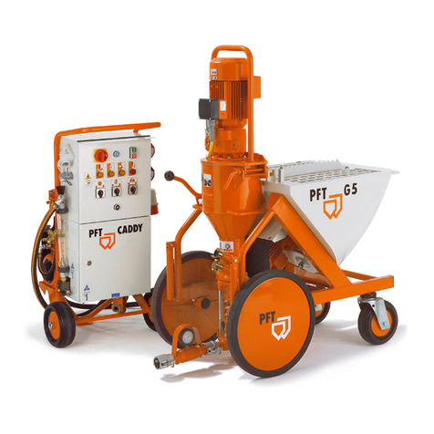
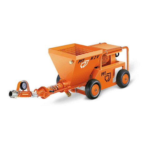
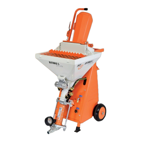
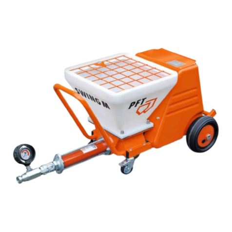
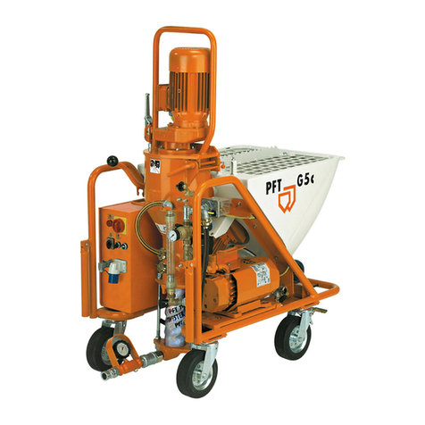
PFT SWING L Series User manual

Contents
14/09/2021
Operating Manual
PFT Conveying Pump SWING L
Part 2, EC Declaration of Conformity
Overview – Operation – Spare Parts Lists
Item number of operating manual: 00209863
Item number of the machine SWING L FU 400V parts list: 00178415
Item number of the machine SWING L 400V parts list: 00197829
Item number of the machine SWING L FU 230V parts list: 00201952
Item number of the machine SWING L FU 230V 3Ph 60 Hz parts list: 00226499
Read the operating manual before starting any work!

2 14/09/2021
© Knauf PFT GmbH & Co. KG
Postfach 60 97343 Iphofen
Einersheimer Strasse 53 97346 Iphofen
Germany
Tel.: +49 (0) 93 23/31-760
Fax: +49 (0) 0 93 23/31-770
Technical hotline: +49 9323 31-1818
www.pft.net

PFT Conveying Pump SWING L Overview – Operation – Spare Parts Lists
Contents
14/09/2021 3
1EC Declaration of Conformity..................... 6
2Examination.................................................. 7
2.1Examination by machine operator....... 7
2.2Periodic inspection .............................. 7
3General information..................................... 8
3.1Information regarding the operating
manual................................................. 8
3.2Keep the manual for future
reference.............................................. 8
3.3Layout .................................................. 8
3.4Retain instructions for later use........... 8
4Technical specifications ............................. 9
4.1General specifications ......................... 9
4.2Connected load 400V .......................... 9
4.3Connected load 230V 60Hz / 50Hz ..... 9
5Operating requirements ............................ 10
6Performance values................................... 10
6.1TWISTER D 6-3................................. 10
6.2R 8-1,5 ............................................... 10
7Sound power level ..................................... 10
8Vibrations ................................................... 10
9SWING L dimensions ................................ 11
10Type plate ................................................... 11
11Quality Control sticker .............................. 11
12Overview of SWING L ................................ 12
12.1Overview of SWING L ....................... 13
13Overview of SWING L control box
00175139 ..................................................... 14
14Overview of SWING L control box
00197825 ..................................................... 15
15Overview of SWING L control box
00207719 ..................................................... 16
16Overview of SWING L control box
00212258......................................................17
17Operating modes........................................18
17.1Pump motor selector switch ...............18
17.2Speed controller .................................18
18Operation.....................................................18
18.1Safety .................................................18
19Description of functions ............................19
20Material ........................................................20
20.1Flow characteristics............................20
21Mortar pressure gauge ..............................21
22Safety instructions .....................................21
23Transport and packaging ..........................22
23.1Safety instructions for transportation .22
23.2Transportation ....................................22
23.3Transportation checklist .....................22
23.4Transportation of existing machines ..23
24Packaging....................................................23
25Safety equipment........................................24
26Hazardous dusts.........................................24
27Setting up the machine..............................25
27.1Monitor the machine...........................25
27.2Preparing the control box with
frequency transformer (FU 400V) ......26
27.3Preparing the control box (400V) .......26
27.4Preparing the control box with
frequency transformer ........................27
27.5Preparing the control box (230V) .......27
27.6Mortar pressure gauge.......................28
28Check direction of rotation........................28
28.1Only for machines with fixed speed ...28
28.2Empty the remaining wallpaper
paste...................................................29
29Filling material into the SWING L..............29

PFT Conveying Pump SWING L Overview – Operation – Spare Parts Lists
Contents
4 14/09/2021
29.1Check the mortar consistency ........... 29
29.2Put the SWING L 400V / 230V into
operation ............................................ 30
30Mortar hoses............................................... 30
30.1Prepare mortar hoses ........................ 30
30.2Connecting the material hose ............ 30
30.3Switch on the SWING L ..................... 31
31Establish air supply ................................... 31
31.1Connect the air hose.......................... 31
32Spraying gun .............................................. 31
32.1Connecting the spraying gun ............. 31
32.2Switch on air compressor 400V
(accessory) ........................................ 32
32.3Switch on air compressor 230V
(accessory) ........................................ 32
33Monitor the machine .................................. 32
34Processing material ................................... 32
34.1Spraying material............................... 32
34.2Speed controller................................. 33
34.3Brief interruptions............................... 34
34.4For longer work breaks / breaks ........ 34
34.5Switch off air compressor 400V
(accessory) ........................................ 34
34.6Switch off air compressor 230V
(accessory) ........................................ 35
35Remote control........................................... 35
35.1Working with the remote control ........ 35
36Switching off in an emergency ................. 35
37Measures in case of power cut................. 36
37.1Main switch to position “0“ ................. 36
37.2Relieve mortar pressure .................... 36
37.3Restart SWING L FU ......................... 37
37.4Restart SWING L 400V / 230V .......... 37
38Work on troubleshooting .......................... 38
38.1Reaction in the event of faults ........... 38
38.2Fault displays ..................................... 38
38.3Malfunctions....................................... 39
38.4Safety................................................. 39
38.5Table of malfunctions .........................40
39Signs for hose blockages:.........................41
39.1Indications of clogged hoses: .............41
39.2Possible causes: ................................41
39.3Earlier damage to the mortar hose.....41
40Removal of blockages in the hose............42
40.1Change the direction of rotation for
SWING L FU.......................................42
40.2Change the direction of rotation for
SWING L ............................................43
40.3Blockage does not dislodge ...............43
40.4Switch the SWING L FU on again
after removing the blockage ...............44
40.5Switch the SWING L on again after
removing the blockage .......................44
41End of work / Cleaning the machine.........44
41.1Securing against restarting.................44
41.2Cleaning the SWING L .......................45
41.3Decouple mortar hose ........................46
41.4Drain the remaining water ..................46
41.5Mörtelschlauch reinigen .....................46
42Clean the pump...........................................47
42.1Remove the pump ..............................47
43Measures in case of risk of frost...............47
44Maintenance ................................................48
44.1Safety .................................................48
44.2When working on and in the control
box......................................................48
44.3Maintenance plan ...............................50
44.4Air filter compressor ...........................50
44.5Tightening torque for the screws on
the material container.........................51
44.6Clean the filter insert for the
frequency converter............................51
44.7Change pump.....................................52
44.8Measures after effected
maintenance .......................................53
44.9 53
45Periodic inspection.....................................53

PFT Conveying Pump SWING L Overview – Operation – Spare Parts Lists
Contents
14/09/2021 5
46Disassembly ............................................... 54
46.1Safety................................................. 54
46.2Disassembly ...................................... 55
47Disposal ...................................................... 55
48Environmental protection ......................... 55
49Operating Manual....................................... 56
50Spare parts lists..........................................56
50.1Accessories / necessary
accessories ........................................56
50.2Catalog ...............................................56
51Index ............................................................57

PFT Conveying Pump SWING L Overview – Operation – Spare Parts Lists
EC Declaration of Conformity
6 14/09/2021
1 EC Declaration of Conformity
Firma: Knauf PFT GmbH & Co. KG
Einersheimer Straße 53
97346 Iphofen
Germany
declares under our sole responsibility that the product:
Type of machine: SWING
Type of equipment: Feed pump
Serial number:
Guaranteed sound power level: 78 dB
mit in conformity with the following CE directives:
Outdoor Directive (2000/14/EC),
Machinery Directive (2006/42/EC),
Electromagnetic Compatibility Directive (2014/30/EU).
Operative Conformity Assessment according to Outdoor Directive 2000/14/EC:
Internal production control as per article 14 paragraph 2 in connection with annex V.
This declaration only refers to the machine in the state in which it has been placed on the market. Parts
subsequently added by the user and/or subsequent interventions are not covered. This declaration ceases to
be valid if the product is converted or changed without consent.
Person authorised to compile the relevant technical documentation:
Dipl.-Wirtsch.-Ing. (FH) Michael Duelli, Einersheimer Straße 53, 97346 Iphofen.
The technical documentation is available from:
Knauf PFT GmbH & Co.KG, Technical Department, Einersheimer Straße 53, 97346 Iphofen.
Iphofen, Dr. York Falkenberg
Managing director
Place, date of issue Name and signature Details of signatory

PFT Conveying Pump SWING L Overview – Operation – Spare Parts Lists
Examination
14/09/2021 7
2 Examination
2.1 Examination by machine operator
Prior to each shift, the machine operator has to examine the
effectiveness of the control and safety devices as well as the
proper fitting of the protection devices.
The safe working condition of construction machinery has to be
checked by the machine operator during operation.
If the safety devices show any defects or if any other defects are
detected that compromise a safe operation, the supervisor has to
be informed immediately.
In case of defects that cause harm to persons, the operation of the
construction machine has to be stopped to eliminate the defects.
2.2 Periodic inspection
Construction machinery has to be inspected for their safe working
condition in accordance with the operating conditions and the
operational requirements as needed, however at least once a year
by an expert.
Pressure vessels have to undergo the prescribed expert
inspections.
The inspection results have to be documented and kept at least
until the next inspection.

PFT Conveying Pump SWING L Overview – Operation – Spare Parts Lists
General information
8 14/09/2021
3 General information
3.1 Information regarding the operating manual
This manual gives important notes and instructions on the correct
use of the equipment. The adherence to all specified safety and
handling instructions is a prerequisite for a safe working
environment.
Additionally, the locally applicable accident prevention regulations
and general safety guidelines for the equipment must be followed
at all times.
Read the entire operating manual carefully before starting any
work! It is an integral part of the product and must be kept near the
machine and accessible to operators at all times.
Always include the operating manual when transferring the
machine to third parties.
The diagrams and illustrations shown in the manual are intended
for better understanding of tasks and descriptions. They are not
necessarily shown to the correct scale and may vary slightly from
the actual equipment used.
3.2 Keep the manual for future reference
The operating manual has to be available during the whole service
life of the product.
3.3 Layout
The operating manual is comprised of three booklets:
Part 1: Safety
General safety instructions for mixing pumps/conveying pumps
Item number: 00172709
Part 2: Overview, operation, servicing and spare part lists (this
booklet).
Part 3: Information sheet for the assembly of the handle
Item number: 00701009
All three parts must be adhered to in order to ensure safe
operation of the equipment. Together, they are valid as one
operating manual.
3.4 Retain instructions for later use
NOTE!
The operating instructions must be available for the
entire service life of the product.

PFT Conveying Pump SWING L Overview – Operation – Spare Parts Lists
Technical spe
14/09/2021 9
4 Technical specifications
4.1 General specifications
Specification Value Unit
Weight 130 - 135 kg
Length 1500 mm
Width 575 mm
Height 665 mm
Container volume 70 litres
4.2 Connected load 400V
Electrical
Specification Value Unit
Voltage, 3-phase current 50 Hz 400 V
Max. current consumption 32 A
Max. power consumption 7.5 kW
Fuse at least 3 x 25 A
Pump motor drive 5.5 kW
Speed range FU 400V 140–440 rpm
Speed range 400V 280 rpm
Pump motor current consumption 11.5 A
4.3 Connected load 230V 60Hz / 50Hz
Electrical
Specification Value Unit
Voltage, AC 50Hz / 60Hz 230 V
Max. current consumption 32 A
Max. power consumption 60Hz 7,5 kW
Max. power consumption 50Hz 5 kW
Fuse at least 3 x 25 A
Pump motor drive 60Hz 5,5 kW
Pump motor drive 50Hz 4 kW
Speed range 60Hz 280 rpm
Speed range 50Hz 70 - 236 rpm
Pump motor current consumption 60Hz 19 A
Pump motor current consumption 50Hz 13,9 A

PFT Conveying Pump SWING L Overview – Operation – Spare Parts Lists
Operating requirements
10 14/09/2021
5 Operating requirements
Ambient conditions
Specification Value Unit
Temperature range 2–45 °C
Relative humidity (maximum) 80 %
Operating period
Specification Value Unit
Maximum continuous operating period 8 hours
6 Performance values
6.1 TWISTER D 6-3
Specification Value Unit
Pumping capacity, approx. 7–23 l/min
Pumping capacity, approx. 14,5 l/min at 292 rpm
Max. operating pressure 30 bar
Pumping distance *, max. for 25 mm 30 m
Pumping distance *, max. for 35 mm 50 m
* Recommended value, depending on conveying height, condition and version of pump,
mortar quality (composition and consistency)
6.2 R 8-1,5
Angabe Wert Einheit
Förderleistung bei FU-Maschine ca. 15-50 l/min
Betriebsdruck, max. 15 bar
Förderweite *, max. bei 35 mm 30 m
* Richtwert bei Fließestrich je nach Förderhöhe, Pumpenzustand und - ausführung,
Materialqualität, - zusammensetzung und -konsistenz
7 Sound power level
Sound power level LWA 78 dB (A)
8 Vibrations
Weighted effective acceleration value to which the upper limbs are exposed = < 2.5 m/s²

PFT Conveying Pump SWING L Overview – Operation – Spare Parts Lists
SWING L dimen
14/09/2021 11
9 SWING L dimensions
Fig. 1: Dimensions
10 Type plate
Fig. 2: Type plate
The type plate contains the following information:
■Manufacturer
■Type
■Year built
■Machine number
■Permissible operating pressure
11 Quality Control sticker
Fig. 3: Quality Control sticker
The following details can be found on the Quality Control sticker:
CE confirmed as per EU directives
Serial number
Controller / signature
Date of control
1500 575
660

PFT Conveying Pump SWING L Overview – Operation – Spare Parts Lists
Overview of SWING L
12 14/09/2021
12 Overview of SWING L
1 2 3 4 5 6
13 12 11 10 9 8 7
Fig. 4: Overview of SWING L
1. Compressor holder (accessory)
2. Material hopper, top section plastic
3. Protective grille for material hopper
4. Magnetic safety sensor
5. Plastic cover
6. Control box
7. Gearbox
8. Plastic wheel
9. Frame
10.Solid coupling with blind cap
11.Castors
12.Pump unit
13.Mortar pressure gauge

PFT Conveying Pump SWING L Overview – Operation – Spare Parts Lists
Overview of S
14/09/2021 13
12.1 Overview of SWING L
12 34
7 6 5
Fig. 5: Overview of SWING L
1. Driver claw
2. Screw pump shaft
3. Tie rods
4. Connection for mortar pressure gauge and
material hose
5. Pressure flange
6. Magnetic safety sensor
7. Display for frequency converter

PFT Conveying Pump SWING L Overview – Operation – Spare Parts Lists
Overview of SWING L control bo
14 14/09/2021
13 Overview of SWING L control box 00175139
1 2 3 4 5 6
9 8 7
Fig. 6: Overview of SWING L
1. Main reversin
g
switch
(
also used as emer
g
enc
y
stop switch
)
2. Pushbutton for operation “ON”
(g
reen
)
/“OFF”
(
red
)
3. Selector switch for rotational direction of pump motor
(
anticlockwise = depressurise pump
)
4. Speed control for material quantit
y
5. Red control lamp
–
motor protection switch activated
6. Green control lamp
–
protective
g
rille
7. Remote control connection
8. Compressor connection
9. Main power suppl
y
connection

PFT Conveying Pump SWING L Overview – Operation – Spare Parts Lists
Overview of S
14/09/2021 15
14 Overview of SWING L control box 00197825
1 2 3 4
7 6 5
Fig. 7: Overview of SWING L
1. Main reversin
g
switch
(
also used as emer
g
enc
y
stop switch
)
2. Pushbutton for operation “ON”
(g
reen
)
/“OFF”
(
red
)
3. Red control lamp
–
motor protection switch activated
4. Green control lamp
–
protective
g
rille
5. Remote control connection
6. Compressor connection
7. Main power suppl
y
connection
400V

PFT Conveying Pump SWING L Overview – Operation – Spare Parts Lists
Overview of SWING L control bo
16 14/09/2021
15 Overview of SWING L control box 00207719
1 2 3 4 5 6
9 87
Fig. 8: Overview of SWING L
1. Main reversin
g
switch
(
also used as emer
g
enc
y
stop switch
)
2. Pushbutton for operation “ON”
(g
reen
)
/“OFF”
(
red
)
3. Selector switch for rotational direction of pump motor
(
anticlockwise = depressurise pump
)
4. Speed control for material quantit
y
5. Red control lamp
–
motor protection switch activated
6. Green control lamp
–
protective
g
rille
7. Remote control connection
8. Compressor connection
9. Main power suppl
y
connection
FU 230V

PFT Conveying Pump SWING L Overview – Operation – Spare Parts Lists
Overview of S
14/09/2021 17
16 Overview of SWING L control box 00212258
1 2 3 4
7 6 5
Fig. 9: Overview of SWING L
1. Main reversin
g
switch
(
also used as emer
g
enc
y
stop switch
)
2. Pushbutton for operation “ON”
(g
reen
)
/“OFF”
(
red
)
3. Red control lamp
–
motor protection switch activated
4. Green control lamp
–
protective
g
rille
5. Remote control connection
6. Compressor connection
7. Main power suppl
y
connection
230V

PFT Conveying Pump SWING L Overview – Operation – Spare Parts Lists
Operating modes
18 14/09/2021
17 Operating modes
17.1 Pump motor selector switch
Fig. 10: Operating modes pump motor
The pump motor has three modes of operation:
Selector switch position "0":
The machine is switched off.
Selector switch on the right (latching) for D and R pumps:
The machine starts when the main switch and the control voltage
are switched on.
Selector switch on the left (latching) for 2L pumps:
Selector switch on the left (latching) for 2L pumps The pump motor
runs backwards, so the pump is relaxed.
17.2 Speed controller
Fig. 11: Speed controller operating mode
The motor speed is set with the potentiometer and the amount of
material is determined.
Low speed →less material.
High speed →more material.
18 Operation
18.1 Safety
Personal safety equipment All machine operators must wear the following safety equipment:
■Protective work clothing
■Safety goggles
■Safety gloves
■Safety shoes
■Ear protection
NOTE!
The warning signs illustrated in this chapter relate to
additional protective equipment that must be worn
for particular working conditions.

PFT Conveying Pump SWING L Overview – Operation – Spare Parts Lists
Description o
14/09/2021 19
Basic information
WARNING!
Danger of injury due to improper operation!
Improper operation can lead to serious injuries or
equipment damage.
Therefore:
Carry out all operating steps according to this
operating manual.
Before starting any work, ensure that all covers
and protective devices are installed and
functioning properly.
Never disable protective devices during
operation.
Keep the operating area clean and tidy.
Components and tools that are stacked on one
another or left lying around can cause accidents.
An increased noise level can cause permanent
hearing loss. Operation can result in noise that
exceeds 95 dB (A) in close proximity to the
machine. Close proximity is defined as the area
within 5 metres of the machine.
For further information see book art. 00142156
General safety instructions for mixing pumps.
19 Description of functions
The PFT SWING L is a conveying pump with an electronic, continuously adjustable direct drive.
Its application is universal, whether fed from buckets or screw mixers.
Fluid, pumpable and solvent-free materials up to a maxium of 3 mm granulation* can be pumped, grouted
and sprayed.
The conveying pump PFT SWING L offers advantages that all users have come to appreciate.
* Recommended value, depending on conveying height, condition and version of pump, mortar quality (composition and consistency)

PFT Conveying Pump SWING L Overview – Operation – Spare Parts Lists
Material
20 14/09/2021
20 Material
For all pumpable ready-mix dry mortar such as:
Adhesive mortar
Reinforcement plaster
Finishing plaster
Plastic plaster
Silicate plaster
SPCC restoration mortar
Multiple component materials
For liquid materials such as:
Emulsion paints
Primers
Betokontakt
Fig. 12: SWING L* - HM
*Accessories 00253076
PFT Protection grille SWING L deeper
For wet products and materials with a paste-like
consistency such as:
Finishing plaster of up to 3 mm granulation
Ornamental plaster
Bentonite
Adhesive mortar
Restoration mortar
20.1 Flow characteristics
NOTE!
The TWISTER D 6-3 pump can be used with an operating pressure of up to 30 bar.
The D 8-1,5 pump can be used with an operating pressure of up to 15 bar
The maximum conveying distance depends primarily on the flow charactistics of the mortar.
Heavy, coarse-grained mortar does not flow well. Fluid mortars, filling compounds and
paints flow easily.
It is recommended to reduce the length of the mortar hose if you exceed an operating
pressure of 30 /15 bar.
To avoid machine breakdowns and excessive wear on pump motor, pump shaft and pump,
always use original PFT spare parts such as:
PFT rotors
PFT stators
PFT pump shafts
PFT material hoses
These components are compatible with one another and form a single constructive unit
together with the machine.
Failure to follow these recommendations will result not only in the voiding of the warranty,
but the quality of the mortar you are producing will also suffer.
This manual suits for next models
1
Table of contents
Other PFT Water Pump manuals

PFT
PFT RITMO XL FC-230/400V User manual

PFT
PFT G4X Super User manual

PFT
PFT FERRO 100 II User manual

PFT
PFT G4X Super User manual

PFT
PFT RITMO XL FU 230 User manual

PFT
PFT 00260621 User manual

PFT
PFT G4X Super User manual

PFT
PFT PFT RITMO User manual

PFT
PFT ZP 3 XXL User manual

PFT
PFT BOLERO 400V User manual
Popular Water Pump manuals by other brands

Waterax
Waterax RANCHER Series quick guide

HERON
HERON 8895105 Translation of the original user manual

Intex
Intex Krystal Clear SF90220T owner's manual

Grundfos
Grundfos UPM3 Installation and operation manual

Pentair
Pentair Berkeley B2X owner's manual

Milwaukee
Milwaukee FORCE LOGIC M18 HUP700R Operator's manual