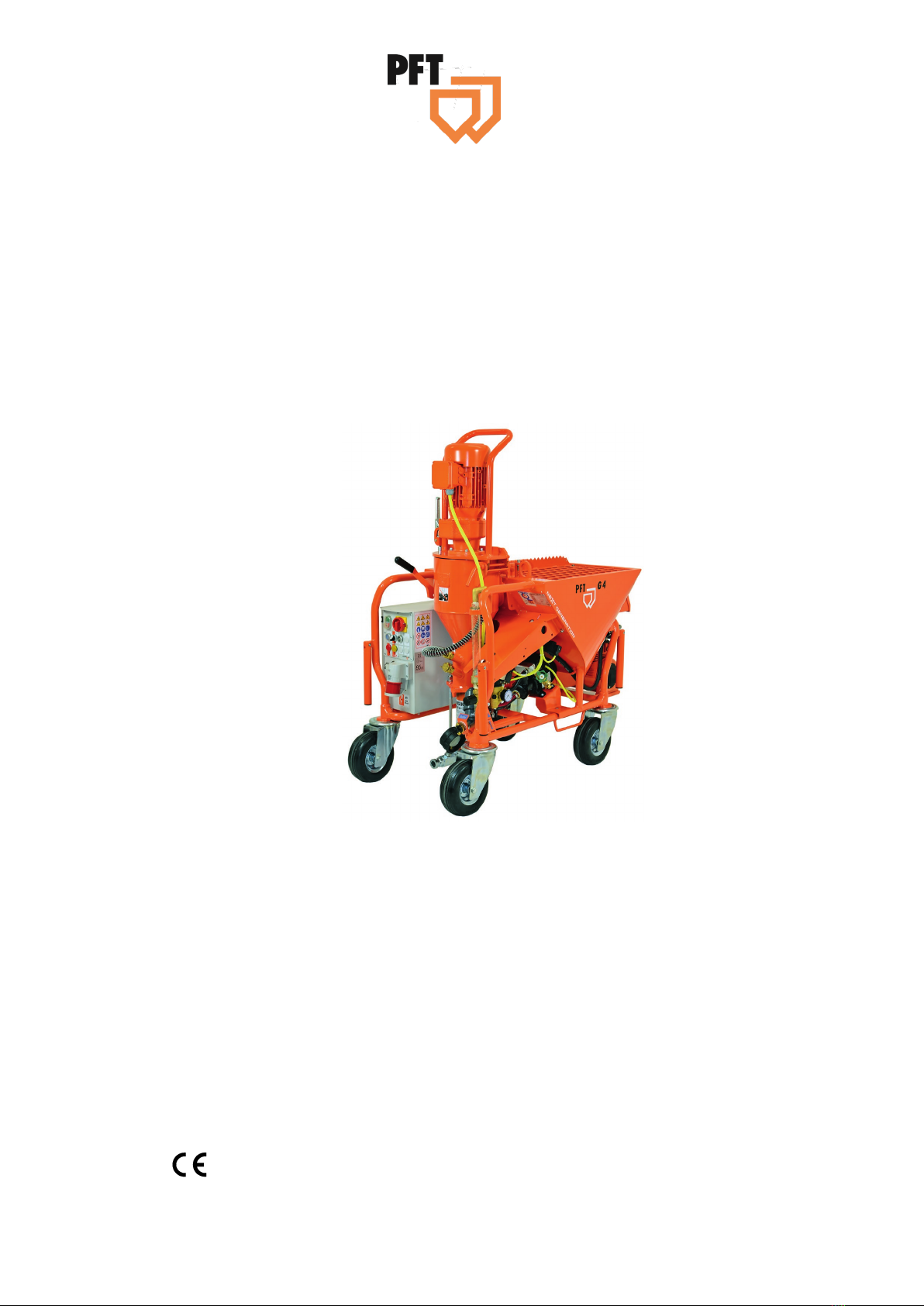
Mixing pump G 4 X smart Overview - Operation and service
Table of Contents
4 2021-08-12
21 Material: ...........................................26
21.1 Flowability / Flow characteristics.......... 26
22 Mortar pressure gauge ...................27
23 Safety rules......................................27
24 Transport, packing and storage ....27
24.1 Safety instructions for transport ........... 27
24.2 Transport inspection............................. 28
24.3 Packaging ............................................ 29
24.4 Transport.............................................. 29
24.5 Transport in individual parts................. 30
25 Operation .........................................30
25.1 Safety ................................................... 30
26 Safety device ...................................31
26.1 EMERGENCY OFF pushbutton........... 31
26.2 Safety system....................................... 32
27 Preparing the machine ...................32
28 Connecting the power supply 400
V ......................................................32
28.1 Check the individual connectors .......... 33
28.2 Connecting the water supply................ 33
28.3 Connection of water from water tank ... 34
29 Switching on the G 4 X ...................34
29.1 Putting the machine into operation ...... 34
29.2 Set water quantity ................................ 34
29.3 Water the mixing zone ......................... 35
30 Mortar pressure gauge ...................35
31 Hazardous dusts .............................36
31.1 Anti-dust unit for G 4 completely.......... 36
32 Fill the machine with dry material..36
33 Monitoring the machine..................37
34 Putting the machine into
operation ........................................38
34.1 Check consistency of mortar................ 38
34.2 Start the machine in a “flying” mode.... 38
35 Mortar hoses....................................39
35.1 Prepare mortar hoses .......................... 39
35.2 Connect mortar hose ........................... 39
36 Compressed air supply ..................40
36.1 Connect air hose.................................. 40
36.2 Connecting the spraying gun............... 40
36.3 Switch on air compressor .................... 40
37 Apply mortar....................................41
37.1 Open the air tap at the spraying gun ... 41
37.2 Interruption of work .............................. 42
37.3 In case of longer interruption of
work/break ......................................... 42
37.4 Switch off air compressor .................... 42
38 Remote control................................43
38.1 Working with the remote control .......... 43
39 Stopping in case of emergency
Emergency-stop switch.................43
39.1 Emergency-stop switch........................ 43
40 Measures in case of power cut ......44
40.1 Main switch to position “0“ ................... 44
40.2 Relieve mortar pressure ...................... 44
41 Work on troubleshooting................45
41.1 Reaction in the event of faults ............. 45
41.2 Fault displays....................................... 46
41.3 Faults ................................................... 46
41.4 Safety................................................... 46
41.5 Table of faults ...................................... 47
41.6 Signs for hose blockages: ................... 49
41.7 Causes for this can be:........................ 50
41.8 Earlier damage to the mortar hose ...... 50
42 Removal of blockages in the hose 50
42.1 Change the direction of rotation of the
mixing pump motor in case of
blockages in the hose........................ 51
42.2 Blockage does not dislodge................. 51