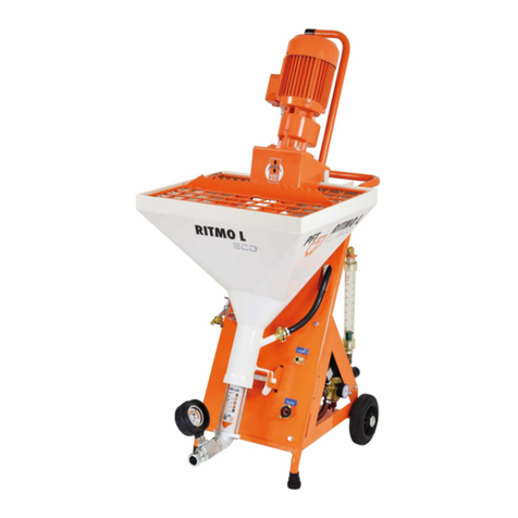
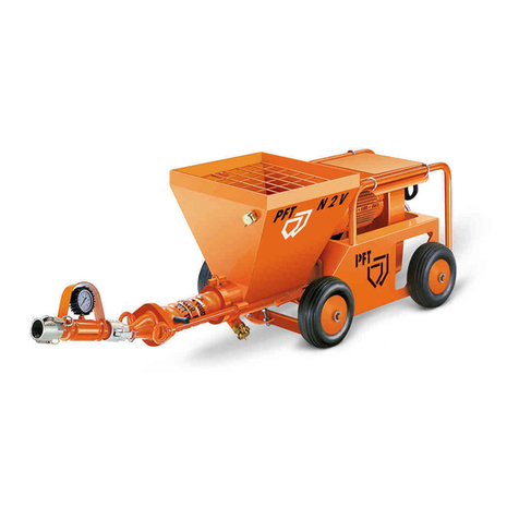
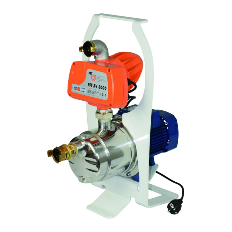
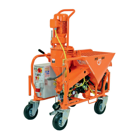
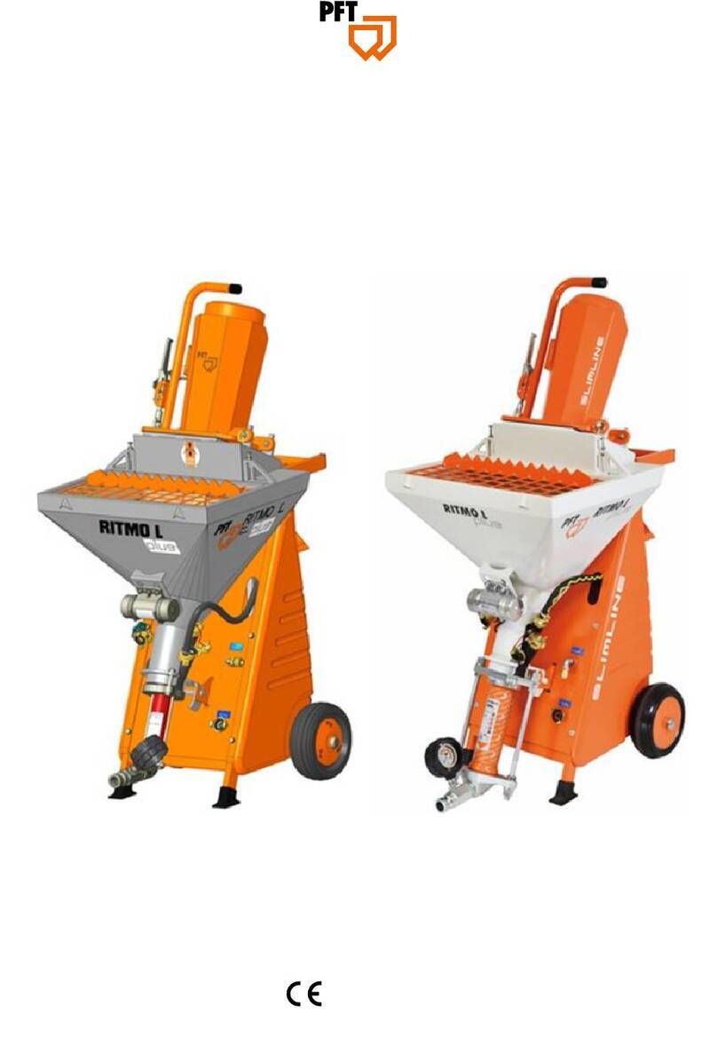
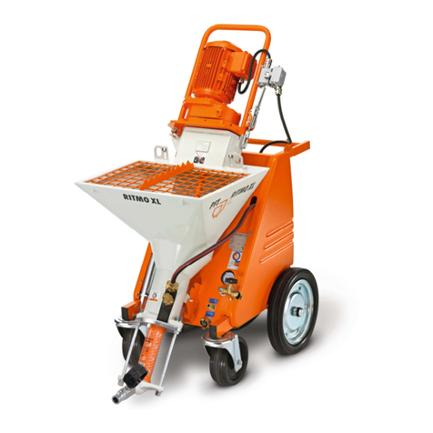
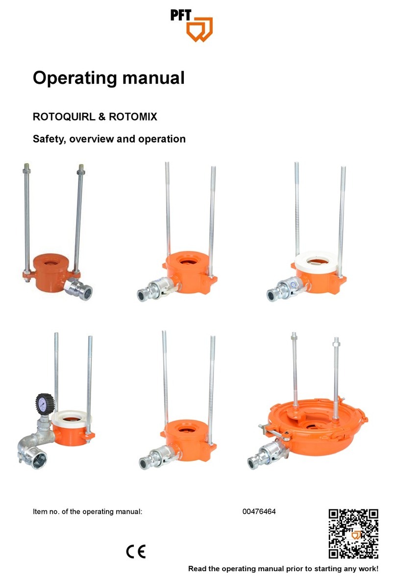
PFT RITMO L FC-230V plus User manual

Contents
2020-03-25
Operating manual
Mixing pump RITMO L FC-230V plus powercoat
Part 2 EC Declaration of Conformity
Overview – Operation
Item number of operating manual: 00132861
Item number of the parts list machine 00667998: RITMO L FC-230V plus powercoat, 1 Ph, 50 Hz,
2,2 kW
Item number of the parts list machine 00659659: RITMO L FC-230V plus powercoat, 1 Ph, 50 Hz,
2,2 kW
Item number of the parts list machine 00659661: RITMO L FC-230V plus powercoat, 1 Ph, 50 Hz,
2,2 kW without spraying gun
Item number of the parts list machine 00631075:
RITMO L FC-230V powercoat – A 2-2,5, 1 Ph, 50
Hz without spraying gun
Read the operating manual prior to beginning any work!

2
2020-03-25
© Knauf PFT GmbH & Co.KG
Postfach 60 97343 Iphofen
Einersheimer Straße 53 97346 Iphofen
Germany
Tel. +49 9323 31-760
Fax +49 9323 31-770
Technical hotline: +49 9323 31-1818
www.pft.net

Part 2 EC Declaration of Conformity Overview – Operation
Contents
2020-03-25
3
1 EC Declaration of Conformity ......................... 6
2 Testing............................................................... 7
2.1 Testing by machine operator................... 7
2.2 Periodic inspection................................... 7
3 General information ......................................... 7
3.1 Information regarding the operating
manual................................................. 7
3.2 Keep the manual for later use.................. 7
3.3 Layout ...................................................... 7
4 Spare part lists.................................................. 8
4.1 Accessories.............................................. 8
5 Technical data................................................... 9
5.1 General specifications ............................. 9
5.2 Electrical data RITMO L plus
powercoat............................................ 9
5.3 Output values RITMO L plus
powercoat............................................ 9
5.4 Operating requirements......................... 10
5.5 Connection values for water .................. 10
6 Sound power level.......................................... 10
7 Vibrations........................................................ 10
8 EMC test .......................................................... 10
9 Dimensions ..................................................... 11
10 Type plate...................................................... 11
11 Quality control sticker.................................. 11
12 Structure RITMO L plus powercoat ............ 12
12.1 Overview RITMO L plus....................... 12
12.2 View from rear RITMO L plus.............. 13
13 Assembles RITMO L plus ............................ 13
13.1 Gear motor with material hopper and
pump unit........................................... 13
13.2 Gear motor........................................... 13
13.3 Chassis with compressor and control
box..................................................... 14
14 Description of assemblies ...........................14
14.1 Overview of control box RITMO L plus
powercoat...........................................14
14.2 Overview of water manifold RITMO L
plus.....................................................15
15 Connections RITMO L plus..........................15
15.1 Connections for water, mortar hose
and air ................................................15
15.2 Mortar hose connection........................16
16 Operating modes...........................................16
16.1 Pump motor selector switch.................16
16.2 Water selector switch ...........................16
16.3 Potentiometer.......................................16
17 Accessories for machine .............................17
18 Intended use of fitting block........................18
18.1 Purpose of fitting block.........................18
18.2 Purpose of solenoid valve....................19
18.3 Purpose of flowmeter ...........................19
19 Description of the PFT pressure booster
pump (accessories)....................................20
19.1 Application area of pressure booster
pump ..................................................20
19.2 Proper use of the machine...................20
20 Preparation of pressure booster pump
(accessories)...............................................21
21 Initial operation, filling the pump ................21
21.1 Putting the pressure booster pump
into operation .....................................21
22 Brief description of RITMO L plus
powercoat....................................................23
23 Material...........................................................24
23.1 Flow characteristics of RITMO L plus
powercoat...........................................24
24 Mortar pressure gauge.................................24
25 Safety regulations.........................................24

Part 2 EC Declaration of Conformity Overview – Operation
Contents
4
2020-03-25
26 Transport, packaging and storage..............25
26.1 Safety instructions for transport...........25
26.2 Closing the motor tilt flange .................25
26.3 Closing the snap lock before transport 26
26.4 Transport checklist...............................26
26.5 Transport in individual parts.................26
26.6 Transport by car...................................27
26.7 Transportation of operational
machines............................................27
27 Packaging......................................................27
28 Operation.......................................................28
28.1 Safety...................................................28
29 Preparation of the machine .........................29
30 Connection to the 230V power supply .......30
30.1 Connection to power distributor ...........30
30.2 Motor connecting cable for pump
motor..................................................30
30.3 Checking the dirt trap screen...............30
30.4 Water supply connection......................31
30.5 Water from water barrel connection.....31
31 Switching on RITMO L plus.........................32
31.1 Putting RITMO L plus into operation....32
31.2 Presetting the water flow rate ..............32
31.3 Watering the mixing zone ....................33
32 Mortar pressure gauge.................................33
33 Hazardous dust.............................................33
34 DUSTCATCHER RITMO L plus SET............34
35 DUSTCATCHER attachment RITMO L
plus SET......................................................34
36 Filling the material hopper with dry
material .......................................................34
37 Monitoring the machine...............................34
38 Putting the machine into operation ............35
38.1 Checking the mortar consistency.........35
38.2 Switching on the RITMO L plus
powercoat with material.....................35
39 Potentiometer ............................................... 35
40 Mortar hoses................................................. 36
40.1 Preparing the mortar hoses................. 36
40.2 Connecting the mortar hose ................ 36
41 Compressed air supply................................ 37
41.1 Connecting the air hose....................... 37
41.2 Connecting the spray gun.................... 37
41.3 Switching on the air compressor ......... 37
42 Switching on the vibrator............................ 38
43 Applying mortar............................................ 38
43.1 Opening the air tap on the spray gun.. 39
43.2 Interruption of work.............................. 39
43.3 In the event of a work stoppage /
pause................................................. 40
44 Working with pastes .................................... 40
44.1 Mortar pressure gauge ........................ 40
44.2 Close water inlet.................................. 40
45 Mortar hose................................................... 41
45.1 Prepare mortar hose............................ 41
45.2 Connect mortar hose........................... 41
46 Filling the material hopper with pastes...... 42
47 Copressed air supply................................... 42
47.1 Connecting the air hose....................... 42
47.2 Connecting the spray gun.................... 42
47.3 Switching on the air compressor ......... 43
47.4 Operation without water....................... 43
48 Applying material ......................................... 43
48.1 Opening the air valve on the spray
gun..................................................... 44
48.2 In the event of a work stoppage /
pause................................................. 44
49 Shutting down in an emergency................. 45
49.1 Emergency OFF switch ....................... 45
50 Measures to be taken in the event of a
power failure .............................................. 45
50.1 Turning the main switch to position “0” 45
50.2 Discharging mortar pressure............... 46
Part 2 EC Declaration of Conformity Overview – Operation
Contents
2020-03-25
5
50.3 Switching on the machine again after
a power failure................................... 46
51 Measures in case of water failure............... 47
52 Troubleshooting ........................................... 47
52.1 Fault displays....................................... 47
52.2 Dealing with malfunctions.................... 47
52.3 Malfunctions......................................... 47
52.4 Safety................................................... 48
52.5 Table of malfunctions........................... 48
53 Pumping stopped / blockage ...................... 50
53.1 Remedying hose blockages / Signs of
blockages........................................... 50
53.2 Causes of clogged hoses: ................... 51
53.3 Pre-existing damage on mortar hose .. 51
54 Clearing hose blockages............................. 51
54.1 Running pump motor briefly in
reverse............................................... 51
54.2 Risk of injury to due overpressure....... 52
54.3 Switching on the machine after
removing a blockage ......................... 53
55 End of shift / Cleaning.................................. 53
55.1 Switching off the energy supplies........ 53
55.2 Cleaning RITMO.................................. 53
55.3 Checking the mortar pressure ............. 54
55.4 Cleaning the mortar hose .................... 54
55.5 Coupling the water hose...................... 55
55.6 Clean mixing tube................................ 55
55.7 Inserting the mixing tube cleaner......... 56
55.8 Cleaning the mixing tube RITMO......... 56
55.9 Cleaning the material hopper............... 56
56 Replacing the pump / Cleaning the pump.. 57
56.1 Placing the machine on its rear............57
56.2 Removing the pump unit ......................57
56.3 Remove the suction flange...................58
56.4 Complementing the remixer with a
pump unit............................................58
57 Switching off RITMO powercoat..................58
58 Measures to be taken if there is a risk of
frost..............................................................59
58.1 Blowing the water manifold dry ............60
58.2 Blowing the water manifold dry ............60
59 Maintenance ..................................................60
59.1 Safety ...................................................60
59.2 Removing the connection cable...........61
59.3 Environmental protection......................62
60 Maintenance tasks ........................................62
60.1 Maintenance plan.................................62
60.2 Dirt trap screen.....................................62
60.3 Dirt trap screen in the water inlet .........63
60.4 Pressure reducing valve.......................63
60.5 Checking the pressure switch ..............63
60.6 After performing maintenance..............64
61 Disassembly ..................................................64
61.1 Safety ...................................................64
61.2 Disassembly.........................................65
62 Disposal .........................................................65
63 Index...............................................................66
64 Notes ..............................................................69

Part 2 EC Declaration of Conformity Overview – Operation
EC Declaration of Conformity
6
2020-03-25
1 EC Declaration of Conformity
Company: Knauf PFT GmbH & Co. KG
Einersheimer Straße 53
97346 Iphofen
Germany
declares, with exclusive responsibility, that the machine
Machine model: RITMO
Device type: Mixer Pump
Serial number:
Guaranteed sound power level: 78 dB
conforms to the following CE regulations:
•Outdoor Noise Directive (2000/14/EC),
•Machine Directive (2006/42/EC),
•Directive on Electromagnetic Compatibility (2014/30/EC).
Applied conformity assessment procedure according to Outdoor Noise Directive 2000/14/EC:
Internal manufacturing inspection as per Article 14, Section 2 in conjunction with Appendix V.
This declaration applies only to the machine in the condition it was in when sold. Components
attached or modifications undertaken by the end customer after purchase remain unconsidered.
This declaration becomes invalid if the product is converted or altered without approval.
Agent responsible for putting together the relevant technical documentation:
Dipl.-Wirtsch.-Ing. Michael Duelli, Einersheimer Straße 53, 97346 Iphofen, Germany.
The technical documentation is held at:
Knauf PFT GmbH & Co.KG, Technische Abteilung, Einersheimer Straße 53, 97346 Iphofen, Germany.
Iphofen, Germany Dr. York Falkenberg
General Manager
Place and date of issue Name and signature Information on signatory

Part 2 EC Declaration of Conformity Overview – Operation
Testing
2020-03-25
7
2 Testing
2.1 Testing by machine operator
Before the start of each work shift, the machine operator must test the effectiveness of the control
and safety devices as well as check the proper attachment of all protective devices.
During operation, construction machines must be tested by the machine operator for their
operational safety.
If defects are found in the safety devices or any other area that could impair safe operation, the
supervisor must be notified immediately.
For defects posing a hazard to persons, the operation of the construction machine must be halted
until the defect is eliminated.
2.2 Periodic inspection
Construction machines must be tested for safe operation by a specialist as the usage conditions
and operating circumstances require, but at least once a year.
Pressure vessels must undergo the prescribed inspections by authorised experts.
The inspection results are to be documented and must be stored at least until the next inspection.
3 General information
3.1 Information regarding the operating manual
This manual provides important information and instructions on the correct use of the equipment.
Adherence to all defined safety and handling instructions is a prerequisite for a safe working
environment.
Additionally, the on-site accident prevention regulations and general safety guidelines for the
equipment must be followed at all times.
Read the manual carefully before starting any work! It is an integral part of the product and must be
kept near the machine and accessible to operators at all times.
Always include the operating manual when transferring the machine to third parties.
The diagrams and illustrations shown in the manual are intended for better understanding of tasks
and descriptions. They are not necessarily shown to the correct scale and may vary slightly from
the actual equipment used.
3.2 Keep the manual for later use
The operating manual must be available during the entire
service life of the product.
3.3 Layout
The operating manual is comprised of two booklets:
Part 1: Safety
General safety instructions for mixing pumps/conveying pumps
Item number: 00172709
Part 2: Overview, operation, servicing and spare part lists
(this booklet).
Both parts must be read and adhered to in order to ensure safe
operation of the equipment. Together, they are valid as one
operating manual.

Part 2 EC Declaration of Conformity Overview – Operation
Spare part lists
8
2020-03-25
4 Spare part lists
You can find spare part lists for the machine in the Internet under www.pft.net
4.1
Accessor
ies
3
For recommended accessories/equipment, see PFT
Machine and Equipment Catalogue or
www.pft.net/plus
1
2

Part 2 EC Declaration of Conformity Overview – Operation
Technical data
2020-03-25
9
5 Technical data
5.1 General specifications
Specification Value
Unit
Weight RITMO L plus powercoat 120
kg
Length with pump 915
mm
Width 600
mm
Overall height 1450
mm
Individual weights
Specification Value
Unit
Chassis / Frame 51.2
kg
Motor with tilt flange 30
kg
Material hopper 18
kg
Hopper dimensions
Specification Value
Unit
Filling height 930
mm
Hopper capacity 45
l
5.2 Electrical data RITMO L plus powercoat
Electrical 230V
EMC Test:
The machine is EMC tested and
meets the strict requirements of
protection class B.
The switch cabinet is equipped
with a mains filter.
Specification Value
Unit
Voltage, AC current 50 Hz 230
V
Max. current consumption 9
A
Max. power consumption 2.5
kW
Fuse 16
A
Pump motor drive 2.2
kW
Pump motor speed range 74 - 492
Rpm
Pump motor current consumption 8.7
A
Vibrator 0.045
kW
5.3 Output values RITMO L plus powercoat
Pump output A2-2,5
Specification Value
Unit
Delivery rate infinitely adjustable 0.8 - 3
l/min
Max. operating pressure 20
bar
Granulation max. 2
mm
Pumping distance*, max. for 25 mm ∅15 m
* Recommended value, depending on conveying height, condition and version of
pump, mortar quality (composition and consistency)

Part 2 EC Declaration of Conformity Overview – Operation
Sound power level
10
2020-03-25
5.4 Operating requirements
Ambient conditions
Specification Value
Unit
Temperature range 2 - 45
°C
Relative humidity (maximum) 80
%
Operating period
Specification Value
Unit
Maximum continuous operating period 8 hours
5.5 Connection values for water
Fig. 1: Water connection
Specification Value
Unit
Operating pressure, min. 2.5
bar
Connection 1/2
inches
6 Sound power level
Guaranteed sound power level L
WA
78 dB (A)
7 Vibrations
Weighted effective acceleration value to which the upper limbs are exposed = < 2.5 m/s²
8
EMC test
The machine has been EMC tested and complies with the strict requirements of EMC Directive filter class B.
The control box is equipped with a line filter.

Part 2 EC Declaration of Conformity Overview – Operation
Dimensions
2020-03-25
11
9 Dimensions
Fig. 2: Dimensions
10 Type plate
Fig. 3: Type plate
The type plate contains the following information:
Manufacturer
Type
Year built
Machine number
Permissible operating pressure
11 Quality control sticker
Fig. 4: Quality control sticker
The quality control sticker contains the following information:
CE confirmed in compliance with EU directives
Serial number
Controlled by / signature
Date of control
600
915
1450
930

Part 2 EC Declaration of Conformity Overview – Operation
Structure RITMO L plus powercoat
12
2020-03-25
12 Structure RITMO L plus powercoat
12.1 Overview RITMO L plus
12
11 10
9 8 7
Fig. 5: Overview RITMO L plus powercoat
1 Engine guard
2 Gear motor
3 Motor guard plate
4 Push handle
5 Water supply to mixing tube / rubber mixing zone
6 Wheel
7 Compressed air from air compressor to spray gun
8 Water inlet, water connection from water supply
9 Rubber mixing zone
10 Remixer
11 Pressure flange
12 Mortar hose connection
13 Mortar pressure gauge
14 Pump unit A2-2,5
15 Suction flange
16 Water extraction valve
17 Vibrator
18 Material hopper
19 Protective grille with bag opener
20 quick fastener
1
2
3
4
5
6
20
19
18
17
16
15
14
13

Part 2 EC Declaration of Conformity Overview – Operation
Assembles RITMO L plus
2020-03-25
13
12.2 View from rear RITMO L plus
Fig. 6: View from rear
1.Motor connection cable.
2.Tool box.
3. Control box.
4. Mains connection 230V.
5. Water manifold.
6. Dummy plug / remove control
cable connection.
7. Water flowmeter (water manifold).
13 Assembles RITMO L plus
13.1 Gear motor with material hopper and pump unit
Fig. 7: Material hopper assembly
The mixing pump PFT RTIMO L plus powercoat comprises the
following main components:
Gear motor with tilt flange, mixing tube with material hopper,
vibrator and pump unit A2-2,5
The gear motor with tilt flange can also be removed from
the material hopper for transport.
Weight: 68.6 kg.
13.2 Gear motor
Fig. 8: Gear motor
Gear motor 2.2kW with tilt flange and protective tube.
Weight: 29.8 kg.
4
3
1
2
3
4
7
6
5

Part 2 EC Declaration of Conformity Overview – Operation
Description of assemblies
14
2020-03-25
13.3 Chassis with compressor and control box
Fig. 9: Frame
Chassis with water manifold and control box.
Weight: 51.2 kg.
14 Description of assemblies
14.1 Overview of control box RITMO L plus powercoat
Fig. 10: Control box connections
1. Sight glass for frequency converter.
2. Potentiometer for motor speed / material volume.
3. Selector switch Vibrator “ON / OFF”.
4. Connection for air compressor COMP R-80 230V (socket
blue continuous current)
5. Connector for vibrator 230 V (socket grey controlled).
6. Connection for main current 230 V, 1Phase, 16 A.
7. Dummy plug / remote control connection.
8. Selector switch Pump.
9. Selector switch Operation with water (as mixing pump),
without water (only as pump).
10.Push button Water supply push.
11.Main switch, also functions as Emergency OFF switch.
1
2
3
4
5
11
10
9
8
7
6

Part 2 EC Declaration of Conformity Overview – Operation
Connections RITMO L plus
2020-03-25
15
14.2 Overview of water manifold RITMO L plus
1 2 3 4 5 6
Fig. 11: Water manifold
1. Pressure reducer
2. Water pressure monitor.
3. Water connection from water supply.
4. Water to mixing tube.
5. Shut-off valve / water outlet.
6. Water outlet for cleaning the mortar
pressure hose.
7. Antifreeze water drain cock.
8. Needle valve for water quantity.
9. Primary water pressure gauge.
10.Solenoid valve.
11.Water flow meter 31,5 – 315l/h.
15 Connections RITMO L plus
15.1 Connections for water, mortar hose and air
Fig.12: Connections
1. Air connection (1) to spray gun (Air compressor external)
2. Water connection from water supply (2).
11
10
9
8
7
1
2

Part 2 EC Declaration of Conformity Overview – Operation
Operating modes
16
2020-03-25
15.2 Mortar hose connection
Fig. 13: Mortar hose connection
1. Mortar hose connection (1) to mortar pressure gauge (2).
16 Operating modes
16.1 Pump motor selector switch
Fig. 14:
Operating modes of
pump motor
The pump motor has three operating modes:
Selector switch position “0”:
The machine is switched off.
Selector switch (latching):
The machine starts up when the main switch is switched on.
Selector switch left (spring return):
The pump motor goes into reverse, thereby relieving the pump
and locking other functions.
16.2 Water selector switch
Fig. 15:
Water selection switch
The RITMO can be used for two application areas:
Selection switch (latching):
The machine is operated without water.
Use as pump.
Selector switch left (latching):
The machine is operated with water.
Use as mixing pump.
16.3 Potentiometer
Fig. 16: Potentiometer
Potentiometer (1) for motor speed / delivery rate:
If the RITMO L plus powercoat is switched on/off with the remote
control within shorter time intervals, fluctuations in material
consistency occur.
The solenoid valve opens from 40Hz. However, this also means that
no water supply is possible with the speed control setting 1-4.
A pictogram below the controller draws the processor's attention to
this setting.
(Parameter value 11 – 75Hz)
1
2
1

Part 2 EC Declaration of Conformity Overview – Operation
Accessories for machine
2020-03-25
17
17 Accessories for machine
Fig. 17
Power cable 3x2.5 mm², 25 m safety socket CEE 16A Art.No.20423420
Fig. 18
Tool bag, mixing pump RITMO L plus powercoat Art.No. 00098808
Consisting of:
Tool roll bag 350 x 400 Art.No. 20048502
Double wrench 13x17 Art.No. 00137015, 17x19 Art.No. 20048512
Double wrench 16x18 Art.No. 00262402, 20x22 Art.No. 00099111
Sponge ball 17 mm fixed Art.No. 00010411
Control box key, double bit 5 mm Art.No. 20444500
Reamer with toolholder Art.No. 00021219
Cleaning brush, brass wire 0.15 mm Art.No. 00098801
Sleeve brush for cleaning RITMO powercoat Art. No. 00090738
Fig. 19
Mixing tube cleaner RITMO L PLUS, zinc-plated Art.No. 00231970
Cleaner shaft BIONIK RITMO D-pump, zinc-plated Art.No. 00588832
Fig. 20
RONDO DN13 hydraulic connection, male part | female part - 15 m Art.No. 00087354
Fig. 21
Extension for remote control cable - 16 m Art.No. 00088049

Part 2 EC Declaration of Conformity Overview – Operation
Intended use of fitting block
18
2020-03-25
Fig. 22
Cleaner coupling 13 female part Geka Art.No. 00087597
Fig. 23
Air hose DN9 Ewo male part | Ewo female part - 16 m Art.No. 00008521
Fig. 24
00094898
Spraying gun powercoat DN13 VA4
1500 Ewo, handle, stainless steel
00098703
Belt for spraying gun RITMO powercoat
18 Intended use of fitting block
18.1 Purpose of fitting block
The equipment has been designed and constructed only for
the intended use described below.
Application range!
Primary use for water and neutral, non-adhesive
liquids. Also suitable for air and neutral non-
flammable gases.
Maximum operating pressure (initial pressure)
16 bar.
After-pressure infinitely adjustable
from 1.5 to 6 bar.
Smallest possible initial pressure 2.5 bar.
Minimum pressure gradient (initial/after-pressure)
1 bar.
Maximum media and ambient temperature 75°C.
Installation position unimportant,
preferably horizontal.

Part 2 EC Declaration of Conformity Overview – Operation
Intended use of fitting block
2020-03-25
19
18.2 Purpose of solenoid valve
Application range!
The flowmeter serves for measuring the volume of
transparent liquid and gas flows in closed pipes.
Optionally, the devices can also be used for flow
monitoring.
WARNING!
Danger due to improper use of the machine!
Improper or unauthorised additional use of the
system can lead to dangerous situations.
Therefore:
Use the machine only for its intended purpose.
Always observe all processing guidelines from
the material manufacturer.
Strictly observe all instructions in this operating
manual.
We accept n o
respo nsibility for dam agesc aused by i mproper or
unauthorise d use.
The owner is solely l iable for all damag eor i njury caused byi mproper or
unauthorise d use.
18.3 Purpose of flowmeter
Application range!
Solenoid valves for liquid and gaseous media,
aggressive or neutral, can be used in various
temperature and pressure ranges
Type 6213 is a 2/2-way straight-through solenoid
valve, closed without power, with a positively
coupled diaphragm system. It switches from 0 bar
and is universal in use for liquids. A minimum
differential pressure of 0.5 bar is necessary
for complete opening.

Part 2 EC Declaration of Conformity Overview – Operation
Description of the PFT pressure booster pump (accessories)
20
2020-03-25
19 Description of the PFT pressure booster pump
(accessories)
19.1 Application area of pressure booster pump
The PFT pressure booster pump is used predominantly as
a high-pressure pump for installation between the mortar mixer
and the mortar mixer pumps when the water pressure is too low.
It can also be used as a primer pump for drawing liquids from
containers, for emptying small tanks and ponds, for pumping
water out of cellars and for irrigation.
The water supply is automatically ensured from a water tank by
the PFT pressure booster pump for the constant water supply to
the PFT machine engineering.
The flow pressure of min. 2.5 bar when the machine is running is
ensured on size by drawing water from the water tank.
Connection example
Fig. 25: Pressure booster pump
and water barrel
00 49 36 86 Item number for the
pressure booster pump AV3000/1
Accessories
Inlet strainer with stainless steel filter screen, 1" suction hose, 2.5 m
Item no. 00 13 66 19
19.2 Proper use of the machine
Caution!
The PFT pressure booster pump only serves for
pumping clean water, recommended for water
relatively polluted with impurities and chemically
non-aggressive liquids. Media with fibrous
and abrasive constituents must be avoided.
Its use is subject to the regulations of
the local legislation.
Other manuals for RITMO L FC-230V plus
1
Table of contents
Other PFT Water Pump manuals
Popular Water Pump manuals by other brands

IWAKI PUMPS
IWAKI PUMPS MDM Series instruction manual

Crown
Crown G6 Installation and operation manual

Graco
Graco 19D873 manual

Chicago Pneumatic
Chicago Pneumatic CP 0077 Safety and operating instructions

GORMAN-RUPP PUMPS
GORMAN-RUPP PUMPS ULTRA V Installation, operation, and maintenance manual with parts list

Carry
Carry CP10 Series owner's manual