SWING M delivery pump / Part 2 Overview, operation and service
Table of contents
Table of contents
1 General information................................... 5
1.1 Information regarding the operating
manual.............................................. 5
1.2 Division............................................. 5
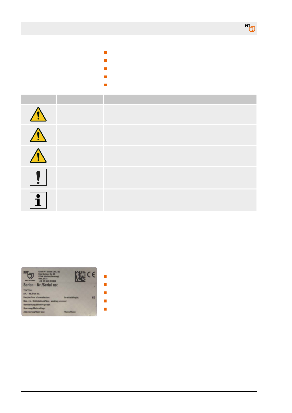
1.3 Display of safety and warning
notices.............................................. 5
1.4 Keep the manual for future refer-
ence.................................................. 6
1.5 Name plate....................................... 6
1.6 EC Declaration of Conformity........... 7
1.7 Quality Control sticker...................... 8
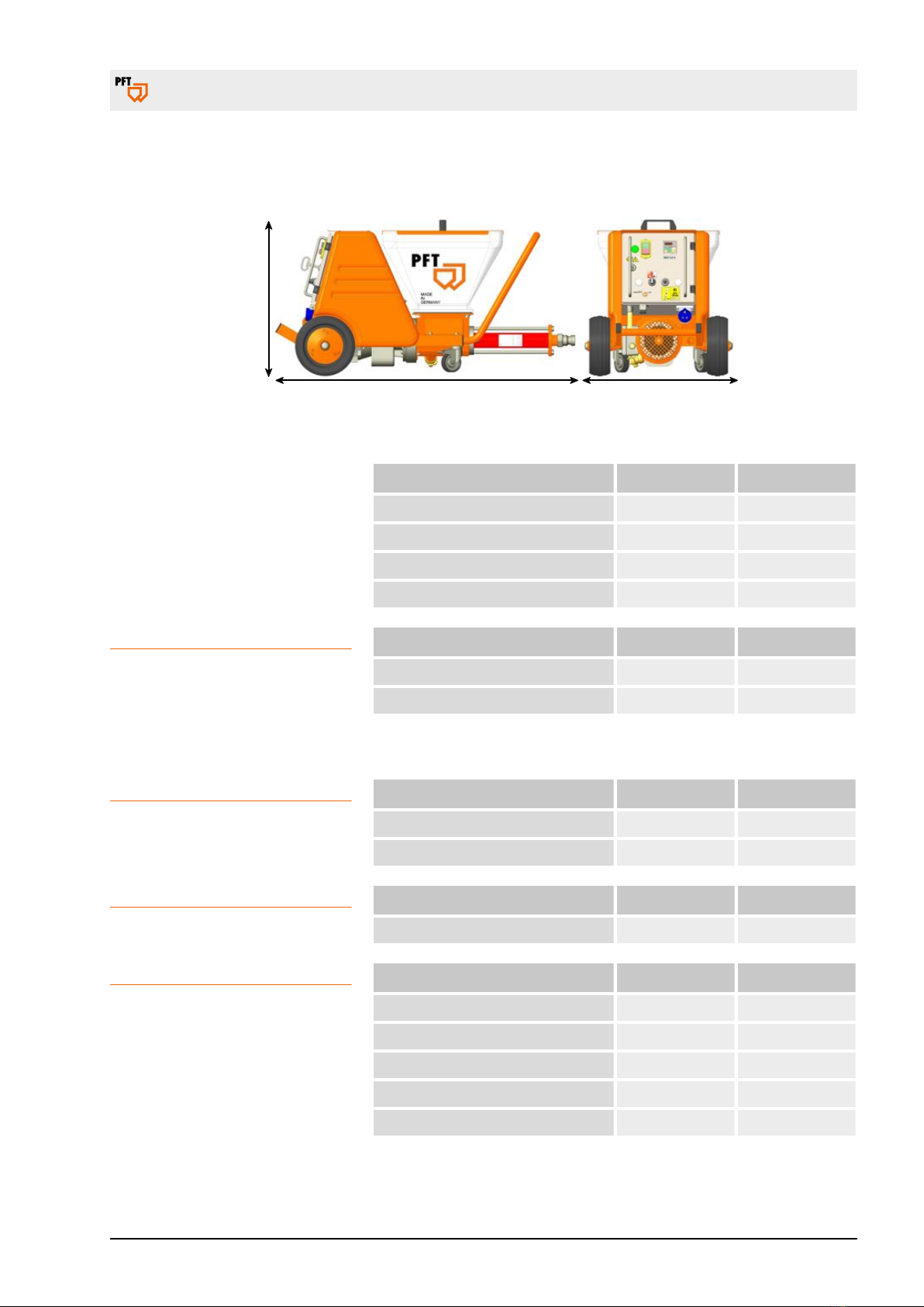
2 Technical data............................................. 9
2.1 General information.......................... 9
2.2 Operating conditions........................ 9
2.3 Capacity values, pump unit B 4–2.... 10
2.4 Capacity values, pump unit C 4-2.... 10
2.5 Sound power level............................ 10
2.6 Vibrations.......................................... 10
3 Transport, packing and storage................ 11
3.1 Safety instructions for transport........ 11
3.2 Transport inspection......................... 12
3.3 Packaging......................................... 12
3.4 Transport.......................................... 13
3.5 Transport by car............................... 13
3.6 Transporting a running machine....... 13
4 Description.................................................. 14
4.1 Overview........................................... 14
4.2 Functional description SWING M..... 14
4.3 Fields of application......................... 15
4.4 Description of assemblies................ 16
4.4.1 Control box item no. 00158813........ 16
4.4.2 Mixing and pumping......................... 16
4.4.3 Material hopper with the tightening
torque of the screws......................... 17
4.4.4 Mortar pressure gauge..................... 18
4.5 Operating modes.............................. 18
4.6 Accessories...................................... 19
5 Operation..................................................... 21
5.1 Safety............................................... 21
5.1.1 Safety rules...................................... 21
5.1.2 Monitoring the machine.................... 22
5.1.3 Hazardous dusts.............................. 22
5.1.4 Mortar pressure gauge..................... 22
5.2 Inspection by machine operator....... 23
5.3 Preparing the machine..................... 23
5.3.1 Risk of injury due to rotating pump
shaft.................................................. 23
5.3.2 Positioning machine......................... 23
5.3.3 Connecting the power supply........... 24
5.3.4 Mortar hoses.................................... 24
5.3.5 Compressed air supply.................... 26
5.3.6 Add material to the machine............ 27
5.4 Shutdown in case of emergency...... 27
5.5 Putting the machine into operation... 28
5.5.1 Avoid hose clogging......................... 28
5.5.2 Feeding material to the machine...... 28
5.5.3 Potentiometer................................... 28
5.6 Applying mortar................................ 29
5.6.1 Open the valves on the spray gun.... 29
5.7 Interruption of work.......................... 30
5.7.1 In case of longer interruption of
work / break...................................... 30
5.8 Switching off the air compressor...... 31
5.9 Switching off the machine................ 31
5.10 Action in case of power failure......... 31
5.10.1 Discharging mortar pressure............ 32
5.10.2 Switching on the machine again
after a power failure......................... 32
5.11 Measures in case of risk of frost....... 33
5.12 Ending work / cleaning the machine. 33
5.12.1 Cleaning........................................... 33
5.12.2 Secure against restarting................. 34
5.12.3 Running the machine empty............ 34
5.12.4 Disconnecting and cleaning the
mortar hose...................................... 35
5.12.5 Cleaning the spray gun.................... 35
5.12.6 Cleaning the material hopper........... 36
5.12.7 Drain residual water......................... 36
5.12.8 Cleaning the pump........................... 37
5.12.9 Tightening torques for the screws
on the material hopper..................... 37
5.13 Reaction in the event of faults.......... 37
5.13.1 Safety............................................... 38
5.13.2 Faults................................................ 38
5.13.3 Fault displays................................... 38
5.13.4 Table of faults................................... 39
5.13.5 Hose blockages................................ 39
5.13.6 Removal of hose blockage............... 40
6 Maintenance................................................ 43
6.1 Safety............................................... 43
6.2 Environmental protection.................. 43
page 3 / 52