PGO PM-NAKED User manual

DEAR CUSTOMERS:
Thank you for choosing PM-NAKED/PMS/PMX of PGO scooter. It
is a fact that the efficiency and sustaining life of each scooter depend
heavily on the operating method of each user. Thus this owner’s manual
will provide you a precise knowledge of easy adjusting, sustaining and
precaution for your scooter. We hope you will read and check it carefully.
Please recognize your scooter model clearly in order to read the
following instruments.
If there is any question, please do not hesitate to ask your
dealer for assistance.
We hope you will enjoy it !
Manufactured by:
Motive Power Industry Co., Ltd.

PARTS NAME for PM model:
Remarks: The accessory equipments shall according to actual vehicle. Above items are only for
function description.
Front brake
lever Rear brake
lever
seat Rear
lamp
Kick
starter
Side stand
Front brake disk
Throttle grip
Front signal
lamp
headlamp
Main stand
muffler
Rear signal
lamp
~4~

PARTS NAME for PMS-50DN (NAKED) model:
Remarks: The accessory equipments shall according to actual vehicle. Above items are only for
function description.
~5~
Front brake lever Rear brake lever
seat Rear lamp
Kick starter
Side stand
Front brake disk
Front signal lamp
headlamp
Main stand
Rear signal lamp
Rear absorber

IDENTIFICATION
1. Recognize your vehicle model according to license document or manufacturing document.
2. This manual includes 5 kinds of engine models:
PMS-50: abbreviated as “PM-50” is 2 stroke (2T) / 50 C.C engine..
PMS-110: abbreviated as “PM-110” is 2 stroke(2T) / 110cc engine.
PMX-50: abbreviated as “PM-50” is 2 stroke (2T) / 50 C.C engine.
PMX-110: abbreviated as “PM-110” is 2 stroke(2T) / 110cc engine.
PM-50 NAKED: abbreviated as “PMS-50DN” is 2 stroke (2T) / 50 C.C engine.
3. Because this manual is suitable for all PM* serial models, there are many different operations
between every model. Once you see a model indication bar appears above the page, for example:
The “ PMS-50DN “ model button lights on, and the lower bar is filled, that means this page is suitable
for “PMS-50DN “.
~6~

IDENTIFICATION
2.Engine No. is located (stamped) on the rear side of the left crankcase.
NOTE:
The upper row is model type, the lower row is the production serial numbers.
Your dealer need this number for ordering the parts, please write down the engine no. for their
reference.
~7~

IDENTIFICATION
3.Vehicle Identification Number (VIN) is located (stamped) inside the inner front cover.
NOTE:
The first 9 digitals are model type, the last 8 digitals are production serial numbers.
Your dealer need this number for ordering the parts, please write down the engine no. for their
reference.
~8~


CONTENT
Warranty Card....................................................... 1
Scooter safety........................................................ 2
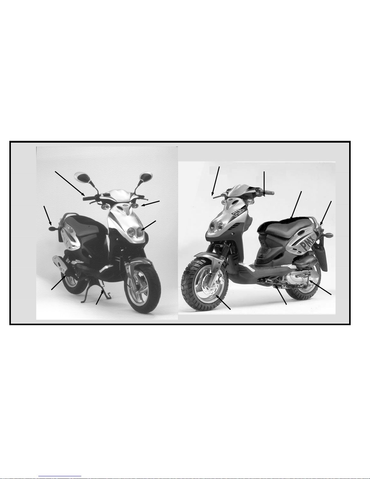
Part location .......................................................... 4
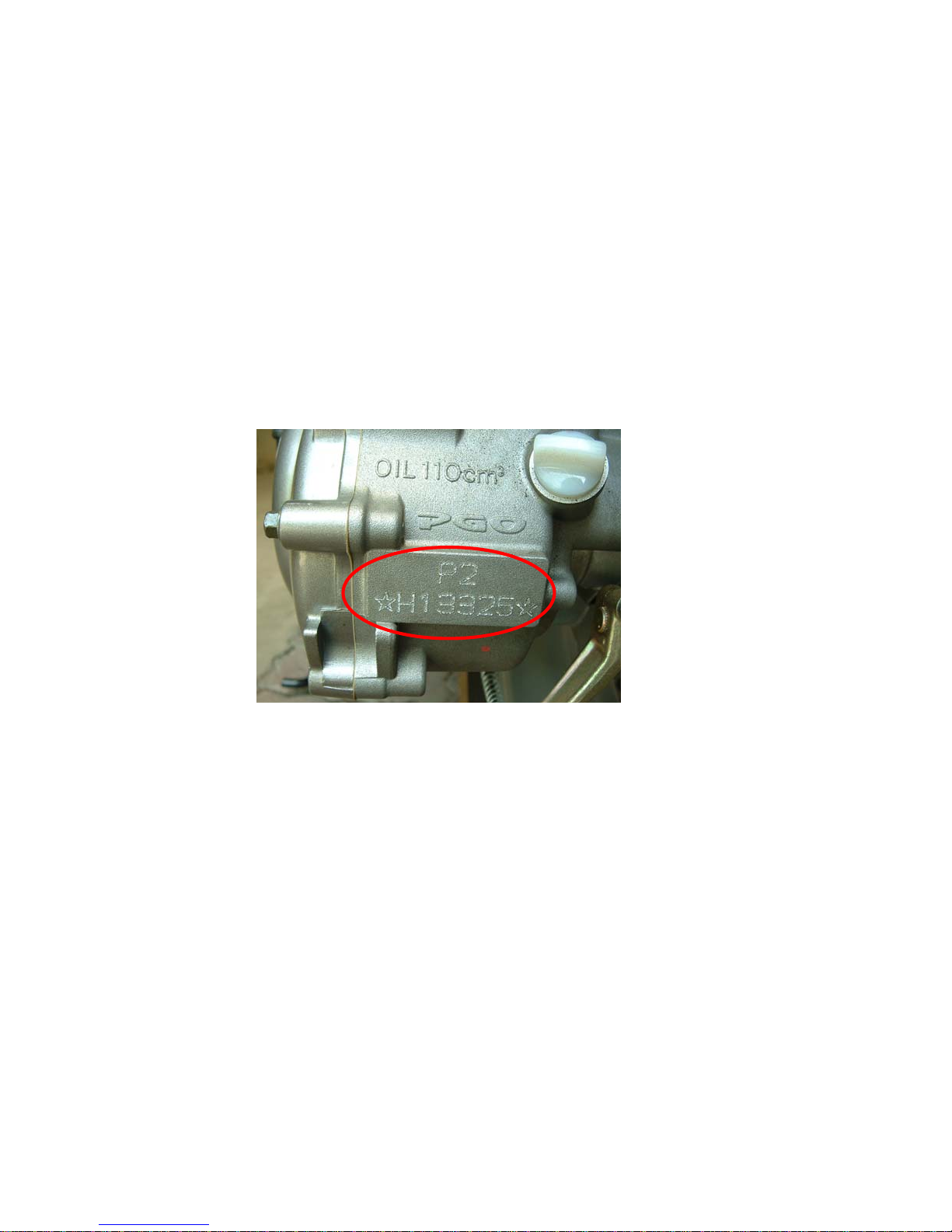
Identification......................................................... 6
The function of switch & controller...................... 9
Main switch .....................................................9
Speedometer ..................................................1 0
Handlebar Controls........................................1 4
Fuel Tank Cap ...............................................1 6
Kick Starter Lever .........................................1 6
Steering Lock.................................................1 7
Seat Lock.......................................................1 7
Luggage Compartment ..................................1 8
Pre-riding inspection .............................................1 9
Brake..............................................................20
Brake Fluid....................................................20
Throttle Grip..................................................22
Lubricant........................................................22
Air Cleaner ....................................................23
Tire.................................................................23
Lamp & Signal Light.....................................26
Notation for operation and riding..........................27
Starting the engine.........................................27
Warming up the engine..................................28
Brake operation..............................................29
Engine initial run-in.......................................30
Parking vehicle ..............................................31
Periodical maintenance........................................ ..32
Periodical maintenance table....................... ..33
The air cleaner ...............................................34
The spark plug ............................................. ..36
Brake adjustment......................................... ..37
Brake fluid check......................................... ..38
Front fork check........................................... ..39
Battery ......................................................... ..40
Specification........................................................ ..41
Wire diagram....................................................... ..45
Periodical maintenance record ............................ ..46

Check List before Delivery
Name:Tel:Age:Sex:
Address:
Model:EngineNo:VIN No:
Delivery date:Year Month day Dealer:
NO Check Item Y N NO Check Item Y N
1 Steering of Handle Bar 8 Confirm Engine No & Document
2 Gap of Brake Lever 9 Owner’s Manual
3 Lights and Horn 10 Operating Method Introduction
4 Fuel Tank and Fuel Kind 11 Periodic Maintenance introduction
5 Engine Oil 12 Warranty Introduction
6 Disk Brake fluid
7 Tire Pressure
Staff Signature:Customer Signature:
Suggestion:
※ Please Sign both customer & service Staff.
※ Mail this chart to agent, and then the Warranty will be effective.

PGO Warranty Card
Name Telephone Registration date
Address
Model
□PM-NAKED
□PMS
□PMX
Displacement
□ 50 CC
□ 110 CC
Engine NO. VIN.No.
Customer Signature Dealer Signature
~1~

SCOOTER SAFETY
▲WARNING
.Scooter riding requires special afford on your part to ensure your safety.
Know these requirements before you ride:
SAFE RIDING RULES
1. Always make a pre-ride inspection(page 19) and perform any needed adjustments or repairs before you ride
the scooter.
2. Many accidents involve inexperienced riders. Most countries require a special scooter riding test or license.
Make sure you are qualified before your ride.
NEVER lend your scooter to an inexperienced rider.
3. Many automobile/scooter accidents happen because the automobile driver does not "see" the motorcyclist.
Make yourself conspicuous to help avoid the accident that wasn't your fault:
- Wear bright or reflective clothing.
- Don't ride in another motorist's "blind spot"
4. Obey all national and local laws and regulations.
- Excessive speed is a factor in many accidents. Obey the speed limits, and NEVER travel faster than
conditions warrant.
-Signal before your make a turn or lane change. Your size and maneuverability can surprise other
motorists.
-~2~

5. Don't let other motorists surprise you. Use extra caution at intersections , parking lot entrances and exits,
and driveways.
6. Keep both hands on the handlebars and both feet on the floorboards while riding. A passenger should hold
on to the scooter or the feet on then passenger foot pegs.
7. Never leave your scooter unattended with the engine running.
8. Moderate your speed when ridding over bumpy roads. Avoid hitting road hazards, such as sharp bumps and
holes, in the road surface. These hazards can cause loss of control or structural damage to the vehicle.
~3~

FUNCTIONS OF EACH CONTROLLER
MAIN SWITCH:
THE MAIN SWITCH CONTROLLING THE IGNI-
TION AND LAMP/LIGHT SYSTEM. THE OPER-
ATION METHODS ARE AS FOLLOW:
1. ON:
ELECTRICAL CIRCUIT IS CONNECTED&ENGINE
CAN BE STARTED. AT THIS MOMENT, THE KEY
CAN’T BE PULLED OUT.
2. OFF:
ALL ELECTRICAL CIRCUITS ARE CUT AT THIS
MOMENT, THE KEY CAN BE PULLED OUT.
3. LOCK:
IN THIS POSITION, THE HANDLE COMP.
CAN BE LOCKED&KEY CAN BE PULLED OUT.
PLEASE REFER TO PAGE 11 HANDLE LOCK
OPERATION.
NOTE: PLEASE TURN TO “OFF” OR “LOCK”
(PULL OUT THE DKY) LOCATION WHEN PARK THE
SCOOTER.
~9~

SPEEDOMETER
1.
SPEED INDICATOR: SHOW THE REAL TIME SPEED .
2.
LEFT TURN LAMP
3.
RIGHT TURN LAMP
4.
OIL WARNING LAMP:
IF THE OIL IS NOT ENOUGH, THE LIGHT WILL BE
“ON”, THEN YOU SHOULD REFILL THE OIL. AFTER
THE OIL IS REFILLED, THE OIL WARNING LIGHT
WILL BE OFF.
WHEN THE MAIN SWITCH IS “ON”, THE OIL
WARNING LAMP WILL “ON” FOR A FEW SECONDS AND
LATER IT WILL BE “OFF” IF THE LAMPIS NOT ON,
THE BULB MIGHT BE BURNED. PLEASE CHECK THE
CIRCUIT SYSTEM OR TAKE IT TO YOUR DEALERS FOR
CHECKING. PLEASE BE SURE THE OIL IS
ENOUGH,THEN YOU MAY RIDE IT.
7
8
9 10
~10~

5.HIGH BEAM LAMP
AS THE ENGINE STARTED, THIS LAMP LIGHTS
INDICATING THAT THE HIGH BEAM IS WORKING.
6.FUEL INDICATOR
INDICATE THE VOLUME OF FUEL IN THE TANK. THE
INDICATOR WILL MOVE FROM “F”( FULL) TO “E”
(EMPTY) AS THE FUEL IS CONSUMING.
WHEN SWITCH OFF, THE INDICATOR WILL
POINTAT THE “E” POSITION.
WHEN ONLY 2 COLUME FUEL IS RESIDUAL, THIS
INDICATOR WILL TWINKLE, PLEASE REFILL FUEL
A.S.A.P.
7.TRIP INDICATOR:
SHOWS HOW MANY (100
METERS) HAVE BEEN TRIPPED SINCE
LAST RESET.
8.ACCUMULATED MILEAGE
SHOWS HOW MANY (KILOMETERS)
MACCUMULATED SINCE THIS
SPEEDOMETER HAS BEEN USED.
9.MODE BUTTON: INTEGRATED INSIDE, NO
FUNCTION !
10.SET BUTTON
THIS BUTTON IS USED FOR RESET
THE TRIP DISTANCE.
TURN ON THE MAIN SWITCH, PRESS
THIS BUTTON 1 SECOND, THEN TRIP
DISTANCE WILL BE RESET TO “0”.
~11~

3 2
1
5.
EACH INDICATOR LIGHT
1.
SIGNAL LIGHT INDICATOR
2.
HIGH BEAM INDICATOR
3.
OIL WARNING LAMP
1.
SIGNAL LIGHT(GREEN):
WHEN OPERATING, THE LAMP WILL FLASH WITH
SOUND.
2.
HIGH BEAM INDICATOR (BLUE): AS THE ENGINE
START-“HI” LIGHTS INDICATING THAT THE HIGH
BEAM IS WORKING.
3.
OIL WARNING LAMP(RED):
IF THE OIL IS NOT ENOUGH, THE LIGHT
WILL BE “ON”, THEN YOU SHOULD REFILL
THE OIL. AFTER THE OIL IS REFILLED,
THE OIL WARNING LIGHT WILL BE OFF
NOTE:
WHEN THE MAIN SWITCH IS “ON”, THE OIL
WARNING LAMP WILL “ON” FOR A FEW SECONDS
AND LATER IT WILL BE “OFF” IF THE LAMP IS NOT
ON, THE BULB MIGHT BE BURNED. PLEASE CHECK
THE CIRCUIT SYSTEM OR TAKE IT TO YOUR
DEALERS FOR CHECKING. PLEASE BE SURE THE OIL
IS ENOUGH,THEN YOU MAY RIDE IT.
~12~

SPEEDOMETER
FUEL GAUGE
INDICATE THE VOLUME OF FUEL IN THE TANK.
THE INDICATOR WILL MOVE FROM “F” FULL TO
“E” EMPTYAS THE FUEL IS CONSUMING. WHEN
THE INDICATOR REACHES TO THE RED AREA,
PLEASE REFILL FUELA.S.A.P.
NOTE: WHEN SWITCH OFF, THE INDICATOR WILL
POINT AT THE “E” POSITION.
~13~

1
23
5
4
HANDLE-BAR CONTROLS
1.HI/LO BEAM SWITCH
HI-The high beam is on
LO-The low beam is on
2.Turn Signal Switch
Move to ←to signal a left turn, →to
signal a right turn.
Press to turn signal off.
3.Horn Button
When the horn button is pressed, the horn will
sound.
4.Starter Button
The starter button (2) is below the headlight
switch (1).
When the starter button is pressed, the starter
motor cranks the engine.
5.HEADLIGHT Switch
ON-Headlight, position light, taillight and
meter light will be on, when the engine is
running.
~14~

REAR&FRONT BRAKE LEVER(HANDLE):
HOLD THE HANDLE &PULL THE LEVER,
THE BRAKE WILL BE OPERATING.
REAR BRAKE FRONT BRAKE
~15~

FUELTANK COVER:
OPEN: INSERT THE KEYAND CLOCKWISE TURN
1/4, THEN THE COVER CAN BE OPENED.
CLOSE: INSERT THE COVER TO ITS ORIGINAL
POSITION AND (COUNTERCLOCKWISE)
TURN BACK & PULL OUT THE DEY.
NOTE: IN ORDER TO FASTEN TIGHTLY, THE
COVER SHOULD BE PUT ON THE ORIGINAL POSI-
TION (ARROW TO ARROW) AS SHOWNG ON THE
PICTURE.
KICK STARTER:
PULL THE KICKS OUT FROM THE ENGINED AND
KICK DOWN, THEN THE ENGINE WILL BE STARTED.
(USE KICK STARTER FOR SUBSTITUTING TO PUSH
THE START BUTTON)
~16~
This manual suits for next models
2
Table of contents
Other PGO Scooter manuals