HVI VLF-34E User manual

Safety,Operation,andProcedureInstructionsfortheVLFSeriesof
ACHipots
Danger- Lethal Voltages:
Equipment to be used bytrained personnelonly
This Operator Manual contains instructions for the operation of a High Voltage power source. The operator of this equipment
must use good judgement and follow all safety precautions noted in this guide to ensure the protection of himself and others in
close proximity to the test area. Failure to follow the instructions could result in injury or
death. Proper grounding of the test set must be done prior to connecting this unit
to a power source.
Mine
VLF-34E
SERIES
Please Refer to
Documentation
Before Operation

VLFOperatorManual
HIGH VOLTAGE, INC.
31 Route 7A
Copake, N.Y. 12516
Phone 518/329-3275 • Fax 518/329-3271
http://www.hvinc.com
E-Mail: factory@hvinc.com

TableofContents
About the Operator Manual 1
SECTION 1
General Information 2
Features and Specifications 2,3
What’s in the Box 4
Operating Environment 5
Safety Symbol Identification 6
SECTION 2
Setting up the Equipment 7,8
Operating the Equipment 9-16
Return Material 17
Terms and Conditions 18,19
Last saved 2/5/2015
T:\DOCUMENTS\Manuals\VLF\VLF-34E\VLF-34E_Manual_R_working.doc

OPERATOR MANUAL
AbouttheOperatorManual
Important
This Operator Manual describes the features and safe operation
of a High VoltageACTest Set. The instructions are intended to be
clear and simple, but the operator must be trained and qualified
according to the customer’s established procedures for the use of
this type of equipment.
This Operator Manual is organized to provide information on the VLF Series in steps that
familiarizethenew operatorwith theentire scopeof operationofthis test set.
Section 1:Specificationsand Controls.
Section2:SetupandOperation.
Section 3:PerformingSpecialOperations.
TheFunctions,Features,andSpecificationsoftheVLFSeriesofACHipotsarealsodiscussedintheVLF
BrochureavailablefromHighVoltage,Inc.
- 1 -

OPERATOR MANUAL
GeneralInformation
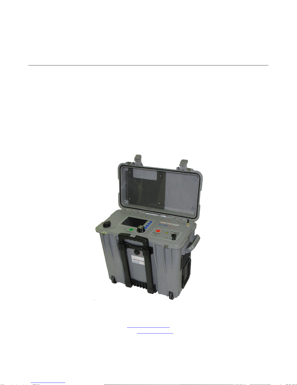
Thissectionfamiliarizestheoperatorwiththefeaturesandspecificationsof the
VLF-34E AC Hipot manufacturedbyHIGH VOLTAGE, INC.
FeaturesandSpecifications
Input Voltage: 115 Vac – 230 Vac, 50 Hz/60Hz, 5A max
Input Fuse: 5x20mm, 250Vac, TypeF
2.5A-250V Input
5.0A–120V Input
HV Output:
0-34 kVac peak/0-24 kVac rms – Sinusoidal
DC: +/- 34 kV
Square wave: 34 kV
Sheath Tester
Voltage Measurement Range 1 - 34 kV peak/1 - 25 kV rms
Accuracy & Resolution 1% & 0.1 kV peak
Current Measurement Range 0 - 15 mA rms
Accuracy & Resolution 1% & 1 μA
Duty: Continuous
Frequency: 0.1 Hz to 0.01 Hz
Load Rating:
0.5 uF @ 0.1 Hz @ 34 kV
1.0 uF @ 0.05 Hz @34 kV
5.0 uF @ 0.01 Hz @34 kV
uF rating increases at lower voltages
Ex: 0.77 uF @ 0.1 Hz @ 22 kV peak
Metering: Voltage kV peak or RMS
SECTION
1
2
2

OPERATOR MANUAL
Current: mA peak or RMS
Calculated: Capacitance, Resistance, Flashover voltage,
Time to Failure
Size/Weight: 19.7” x 12.0” x 18”, 45 lbs.
500mm x 305mm 458mm, 21 kg.
Case: Hard “Pelican”type case with extendable
handle and wheels
HV lead: 20’ RG8/U, Ground 20’ #2
Fault: Smart Fault Management
or shutdown on Fault
Reports: Test Records stored in non-volatile
memory or via USB memory stick
PC Interface: USB, xbee(r)wireless, RS-232/422
PC Software: RemoteControl& Test Reports
SystemRequirements: WindowscompatibleHardware
500Mhzorfasterprocessor
At least512MBof RAM
WindowsXP, Vista, Windows7
3
3

OPERATOR MANUAL
CAUTION: Disconnect all power before servicing.
There are no user serviceable parts.
Service should be performed byQualified personnel
4
4

OPERATOR MANUAL
What’s in the Box
1. VLF-34E
2. Ground Stick with 20 ft. of ground wire
3. Green/Yellow Lead with Green Boot
4. 20ft. 2 AWG Cable
5. 20ft. HV Output Lead
6. Input Line Cords
7. Safety Ground Lead "Y" Assembly
8. Manual
9. Bag
10. Enable Key
11. USB w/ Software and Manual
12. X Stick
5
5

OPERATOR MANUAL
Operating Environment
Indoor/Outdoor-fair weather
Case Lid Open – IPX0
Case Lid Closed IPX2
Altitude: 100% of rating;Sea-level, up to 5000ft.(approx.1500M). The output
power is de-rated 10% above 5000 ft. altitude, 20% above 12,000 ft.( approx.
3600M), and 30% above 15,000 ft.(approx. 4500M)
Storage Temperature: -20°C to 70°C(-4°F to 158°F)
Operating Temperature: -5°C to 45°C(22°F to 113°F) Output power is de-
rated linearly by 15% from 30 to 45°C ambient.
Maximum Relative Humidity: 80% up to 31°C(88°F), decreasing linearly to
50% at 40°C(104°F)
Mains supply fluctuation: +/-10% of rated voltage
Installation: Category II
Pollution: Degree 2
6
6

OPERATOR MANUAL
Safety Symbol Identification
Warning! Please refer to documentation before
operation
Protective Earth Terminal
Warning: Hazardous Voltage
7
7

OPERATOR MANUAL
SETTINGUPTHEEQUIPMENT
The setup of thisequipment hasbeen minimized by careful considerationof the operator during
design. The VLF-34E single-piece construction and light weight lends itself to convenient
portabilityforACtestingin the field.
Select a location for the unit that will allow easy viewing of the control panel at a safe
distancefromthetestobject (within 20ft.)on a levelarea.
Note: The mains outlet that is utilized to power this equipment must be within 3 meters of
the device, and shall be easily accessible and easily disconnected.
1. Be sure that main power switch lower left side of case is off.
2. Secure a ground test lead to the ground stud on the right side of
the case
–CAUTION –
No switches or Disconnect devices in the earth conductor.
Disconnection ofthe protective earth conductor, will impair the
protection provided by the system
3. Wire the input power cord to a grounding-type plug rated for a
minimum of 250V, 10A and compatible to the local power
receptacles.
4. Connect the input line cord (maximum length 3 meters)to mains
outlet.
5. Connect the safety ground stick to a solid earth ground.
6. Insert the coaxial output cable into the High voltage output dry-well
on the right side of the case and stretch out for later connection to
the test cable or load.
SECTION
2
8
8

OPERATOR MANUAL
7. Insert the EXT INTLK plug into the socket on the left side panel.The
plug may also be wired to a normally open contact of a safety switch for added
protection.
-IMPORTANT NOTE -
DO NOT BLOCK THE COOLING VENTILATION OPENINGS
The setup of the VLF AC Test Set does not address the need for proper safety
grounding of the load (test sample or cable). The grounding requirements vary for
different types of tests. Please consult the local electrical codes where applicable or
reference the guidelines for grounding found under OPERATING THE EQUIPMENT.
9
9

OPERATOR MANUAL
OperatingtheEquipment
This section provides step-by-step instruction on various test methods. Many facilities
have their own in-house test procedures, and this manual is not to supercede these.
The purpose of this section is to explain the capabilities of this test set in real-world
applications.Only trained personnel should attempt to operate this equipment.
Dangerous voltages and currents are produced during the testing of cables, only
trained individuals should operate this type of equipment and access to the test
area must be restricted during testing toavoid endangering others.
OPERATING THISEQUIPMENT IN A MANNER NOTSPECIFIED BYTHE
MANUFACTURER MAY IMPAIR THE PROTECTION PROVIDED BY THIS
EQUIPMENT
When testing cables, either single or three phase, there are certain extra steps that must be
observedtoensuresafe operation.
ACTesting of High Voltage Cables
1. Ensure that all the steps listed in Setting Up the Equipment have been
accomplished.Takespecialnotetogroundthetestsettoasolidearthground.
Caution!!
Before making any cable connections, ensure that the cable
being tested has been properly identified, de-energized,
and grounded!
2. Make sure that all insulators, stress cones, and pot heads are clean and free of
moisture.Thiswillpreventflashoverandminimizeleakage.
Note: Be aware that any lightning arrestor or transient suppressing device must
be disconnected if the clamping voltage is below the test voltage being
performed. Failure to clear these devices from the cable may result in a false
failure indication of the test cable.
3. Isolate the far end of the conductors under test forthe test voltage; that may mean
separating some of the conductors in a multi-conductor cable from each other and
theirshields.
10
10

OPERATOR MANUAL
The shields of all cables must be securely tied to
ground at the nearest end of the cable.
4. Any conductors or wires in the cable or the vicinity not being tested must be
groundedtoavoidabuildupofchargeandpossibleshockhazard.
5. Voltagemustbe applied accordingto specifications from the cable manufactureror
anyotherapplicable test standards
6. Prior to connecting anything to the test sample, be sure the test sample is
identified,de-energizedandgroundeduntilreadytotest.
7. Connect the input power cable to a grounded, 50/60 Hz source as noted in
SETTING UP THEEQUIPMENT. Ageneratorisanacceptablepowersource.
8. Connecttheoutput lead to the testsample. Besure that there is enough clearance
to grounded objects for the expected test voltage. The minimum clearance in air is
10kVac/inch.
9. Turn ontheMAIN POWER switch nearinputpowerreceptacle.
***CAUTION***
POTENTIALLY LETHAL
VOLTAGES MAY BE PRESENT
STORED ENERGY LEVELS IN THE CABLE GREATLY
INCREASE THE RISK OF FATAL INJURY IF CONTACT
IS MADE WITH THE LOAD WHILE AT ANY VOLTAGE.
10. Clear the test area of unauthorized personnel and use safety barricades to
warn others of potential danger during the highvoltage test.
11
11

OPERATOR MANUAL
Line LED
Indicates inputpower is present
USB Data
Transfer test results via USB flash drive to PC app for test report
Save results directly, if USBflash drive is present whilethe test is performed
Menu Selection
Rotate the selector knob toscrollthrough menu items. To select and adjust a
menu item push the knob or push the green accept button. When the test
parameter is adjustedto the desired level push the knobor the green select button
to return to the menu items.
Main Menu Screen
Last Test Setup
Repeats last test performed
Saved Test Setup
Pick a preprogrammed test profile or sequence from memory
A profile is a test with up to 5 steps
A sequence is two or more profiles run in succession
New Test Setup
Set up test parameterson the fly
Advanced
Setup Sequences
Setup Profiles
Review Test Results
HV Status LED
Green indicates voltage on DUT (Device Under Test) is less than 250 Volts
Yellow indicates Caution High Voltage is about to be applied
Red High Voltage is present
12
12

OPERATOR MANUAL
Select new test setup to enter manual mode. Use the scroll knob to cycle through the test
parameter options. Once your test is set to your parameters press start, top right button.
The screen will turn yellowconfirm yoursettingsand press staragain. The screen turns
red and the test willstart.
Manual Mode
Waveform
Sin Wave
Square Wave
DC +/-
Frequency
Auto
0.1 – 0.01 Hz
Step
1-5
Voltage
0-34 kV
Duration
15, 30, 60 mins
Phase
A, B, C
Location
Alphanumeric entry
Circuit ID
Alphanumeric entry
13
13

OPERATOR MANUAL
Confirmation Screen
Confirm test parameters
Press Start (Round Blue Button top right of screen)
14
14

OPERATOR MANUAL
VLF34E Connection to PC Application
Insert Xstick (green USB Thing) into USB port on your PC
Install the xstick drivers, USB stick (red has HVINCLogo) with unit if asked for
drivers
Copy VLF-34E PC App exefile to your PC (it’s on the red USB stick)
Open VLF-34E PC Application
Click Wireless Configuration Button
15
15

OPERATOR MANUAL
Click Next
16
16

OPERATOR MANUAL
Click Begin
After the wireless communication havebeen configured click next
Click the Connect to VLF Button
PC Application Uses
Creating Test Profiles / Sequences
Test Reports
Live test monitoring
Wireless Remote Control
17
17
Table of contents