PHARO WellSpring 130 User manual

WellSpring
Pharo® Dampfdusche
Pharo®WellSpring 130 29620XXX
Montageanleitung
Installation Instructions
Istruzioni di montaggio

2
INHALTSVERZEICHNIS
Masse 3
Bestandteile 4
Technische Daten 10
Vorwort 15
In der Anleitung Verwendete
Symbole 16
Sicherheitsvorschriften 18
Benötigtes Werkzeug 20
Montage Acrylelemente 22
Sichtdichtungen Montage 42
Trägerplatten Montage -Optional- 44
TürMontage 48
Montage Eckschrank 56
Montage Eckpaneel 58
Funktionsprüfung K IV Steam Plus 66
Endmontage 68
Safety Function 70
Thermostat justieren K IV Steam Plus72
Verkleiden der Kabine 74
Steuerung K IV Steam Plus 76
Bedienung (ML/Steam) 88
Bedienung 90
Reinigung/ Wartung 94
Entkalken 96
CONTENTS
Dimensions 3
Components 4
Technical Data 10
Foreword 15
Symbols Used in the Instructions 16
Safety Precautions 18
Required Tools 20
Installation Of Acrylic Elements 22
Visible seals Installation 42
Mounting Plates
Installation (optional) 44
Door Installation 48
Corner Cabinet Installation 56
Corner Panel Installation 58
Functional Check K IV Steam Plus 66
Final Work 68
Safety Function 70
Thermostat Adjustment
K IV Steam Plus 72
covering the cabin 74
K IV Steam Plus Control 76
Operation (ML/Steam) 88
Operation 90
Cleaning/ Maintenance 94
Decalcifying 96
INDICE
Ingombri 3
Componenti 4
Parti di ricambio 6
Introduzione 15
Simboli utilizzati nel manuale 16
Prescrizioni di sicurezza 18
Utensili richiesti 20
Montaggio degli Elementi Acrilici 22
Inserire le guarnizioni a vista 42
montaggio piastra di
supporto (opzionale) 44
Montaggio della Porta 48
Montaggio dell'armadietto angolare56
Montaggio del pannello angolare 58
Controllo del funzionamento K IV
Steam Plus 66
Montaggio finale 68
Safety Function 70
Taratura del termostato
K IV Steam Plus 72
Riverstimento della Cabina 74
Controllo K IV Steam Plus 76
Uso (ML/Steam) 88
Uso 90
Pulizia/ Manutenzione 94
Per togliere il calcare 96

3
Pharo®WellSpring 130 29620xxx
Deutsch
MASSE
English
DIMENSIONS
Italiano
INGOMBRI

4
BESTANDTEILE
WELLSPRING 130
Karton 1 (2170x650x620 mm / 30 kg)
Sitzelement 1
Karton 2 (2170x800x150 mm / 28 kg)
Seitenelement 1
Karton 3 (2170x800x150 mm / 28 kg)
Seitenelement 2
Karton 4 (1350x1350x250 mm / 20 kg)
Dachelement
Karton 5 (2170x650x620 mm / 30 kg)
Sitzelement 2
Karton 6 (2170x1350x240 mm / 36 kg)
Türelement
Tür
Karton 7 (2170x500x420mm / 45,5 kg)
Eckpaneel
Eckschrank
Zubehör (Befestigungsteile)
Karton 8 *(2170x800x150 mm / 35 kg)
Trägerplatten
Karton9 *(1350x1350x250 mm / 30 kg)
Duschwanne/ Rahmen
* Option
COMPONENTS
WELLSPRING 130
Carton 1 (2170x650x620 mm / 30 kg)
seat element 1
Carton 2 (2170x800x150 mm / 28 kg)
side element 1
Carton 3 (2170x800x150 mm / 28 kg)
side element 2
Carton 4 (1350x1350x250 mm / 20 kg)
roof element
Carton 5 (2170x650x620 mm / 30 kg)
seat element 2
Carton 6 (2170x1350x240 mm / 36 kg)
door element
door
Carton 7 (2170x500x420mm / 45,5 kg)
corner panel
corner cabinet
accessories (mounting parts)
Carton 8 * (2170x800x150 mm / 35 kg)
mounting plate
Carton 9* (1350x1350x250 mm / 30
kg)
shower tray/ frame
* Option
COMPONENTI
WELLSPRING 130
Imballo 1 (2170x650x620 mm / 30 kg)
elemento sedile 1
Imballo 2 (2170x800x150 mm / 28 kg)
elemento laterale 1
Imballo 3 (2170x800x150 mm / 28 kg)
elemento laterale 2
Imballo 4(1350x1350x250 mm / 20 kg)
elemento porta
Imballo 5 (2170x650x620 mm / 30 kg)
elemento sedile 2
Imballo 6 (2170x1350x240 mm / 36
kg)
piastre di supporto
opzione
Imballo 7(2170x500x420mm / 45,5 kg)
pannello angolare
armadietto angolare
accessori opzionali (elementi di mon-
taggio)
Imballo 8 * (2170x800x150 mm / 35
kg)
superfici
Imballo9*(1350x1350x250 mm / 30 kg)
piatto doccia
* Opzionale

5
4
1
2
3
9 *
56
7
8*
DeutschEnglishItaliano

6
Pos. VE
xxx
000
090
320
410
420
450
460
800
810
880
97024xxx
97071980
97071980
97079000
97080000
97081000
97082000
97083000
97084000
97085000
97086000
97087000
97458000
21880xxx
97088000
21881000
97044000
28406xxx
28409xxx
28408xxx
97095xxx
25944000
97098000
36391xxx
95032xxx
94282000
36991xxx
97099xxx
94142000
97056xxx
97057xxx
96645000
97110000
97920000
25941xxx
17850xxx
28530xxx
28547xxx
38850xxx
96928000
97103000
25948000
97922000
97484000
97485000
97541000
96646000
27521xxx
25933000
25958xxx
98602000
1
1
1
1
1
1
1
1
1
1
1
1
1
1
1
1
1
1
1
1
1
1
1
1
1
1
1
1
1
1
1
1
1
1
1
1
1
1
1
1
1
1
1
1
1
1
1
1
1
1
1
1
2
3
4
5
6
7
8
9
10
11
12
13
14
15
16
17
18
19
20
21
22
23
24
25
26
27
28
29
30
31
32
33
34
35
36
37
38
39
40
41
42
43
44
SERVICETEILE
Bezeichnung Nr./Nr./No.
Schieber kpl.
Eckpaneel kpl.
Eckpaneel kpl.
Duftbefülleinheit kpl.
Deckel
Sieb
Duftbegrenzer
Duftbehälter
Magnetventil
Levelsensor
Dampfgenerator kpl.
Heizspirale
Dampfaustrittsdüse
Schrauben Set
Schaltkasten
Glasplatte
Befestigungssatz
Strahlkörper (Normalstrahl)
Strahlkörper (Nebelstrahl)
Strahlkörper (Massagestrahl)
Rosette
Seitenbrause
Dichtung Eckschrank/Paneel
Thermostatgriff
Hülse
Temperatur Regeleinheit
Griff
Hülse
Absperrventil
Griff
Hülse
Einsatz Ab-/Umstellung
Steuerung K IV LITE STEAM
Steuerung K IV STEAM PLUS
Brauseschlauch
Handbrause AX Carlton
Handbrause AX Starck
Handbrause HG Aktiva A8
Handbrause AX Uno
Schwallbrause
Absperrventil
Schlauchanschlußwinkel
Temperaturfühler
Duftstoffbehälter
Magnetventil
Rosette
Magnetventil
Wandhalter für HB (Porter'C)
Glasablage
Halteelement
Deckel (flüssig Duftstoff)
Oberflächen
chrom
chrom/gold
weiß (alpin)
pergamon
platin
weiß
grau
steel
satinox
edelmatt
SPARE PARTS
Description
support, assy
corner panel cpl.
corner panel cpl.
fragrance device cpl.
cover
sieve
fragrance adjusting
fragrance reservoir
solenoid valve
level sensor
steam generator cpl.
heating element
Steam Outlet
screw set
switching Box
glass plate
mounting kit
body spray jet (normal jet)
body spray jet (fine spray jet)
body spray jet (massage spray jet)
escutcheon
body shower
seal corner cabinet/panel
handle for thermostat
sleeve
thermostat cartridge
handle
sleeve
isolating valve
handle
sleeve
cartridge on/off control
control K IV LITE STEAM
control K IV STEAM PLUS
shower hose
handshower AX Carlton
handshower AX Starck
handshower HG Aktiva A8
handshower AX Uno
surge shower
isolating valve
hose connection angel
temperature sensor
tank for 'aromatics'
solenoid valve
escutcheon
solenoid valve
wall holder for hand shower (Porter'C)
shelf
support element
cover (fluid aromatics)
Colors
chromeplated
chromeplated/goldplated
white (alpin)
pergamon
platin
white
grey
steel
satinox
satin chrome
PARTI DI RICAMBIO
Descrizione
cursore completa
pannello angolare completo
unitàriempimentodisostanzearomatiche
coperchio
filtro
limitatore sostanza aromatica
recipiente per sostanza aromatica
valvola elettromagnetica
sensore livello
generatore di vapore
spirale di riscaldamento
ugello di fuoriuscita vapore
set di viti
cassetta di contenimento
lastra di vetro
set di fissaggio
diffusore (getto normale)
diffusore (getto a spruzzo)
diffusore (getto massaggio)
copertura
doccia laterale
guarnizione angoliera / pannello
manopola termostatico
cappuccio
elemento termostatico
manopola
cappuccio
valvola d'arresto
deviatore
cappuccio
cartuccia rubinetto / deviatore
scatola di comando K IV LITE STEAM
scatola di comandoK IV STEAM PLUS
flessibile
doccetta AX Carlton
doccetta AX Starck
doccetta HG Aktiva A8
doccetta AX Uno
getto d’acqua
valvola d'arresto
tubo di raccordo per flessibile
termosensore
recipiente per essenza aromatica
valvola elettromagnetica
copertura
valvola elettromagnetica
supporto per HB (Porter'C)
ripiano in vetro
anello di tenuta
coperchio (essenza aromatica
liquida)
Couleures
cromato
cromato/oro
bianco (alpino)
pergamon
platino
bianco
grigio
steel
satinox
satinato

7
2
1
18
20
21
22
23
24
25
26
27
28
18
1
30
29
31
31
32 32
33
3
36
5
6
8
74
9
10
12
11
13 14
15
16
17
19
34 35
37
38
40
44
6
39
43
41
42
DeutschEnglishItaliano

8
Pos. VE
97613980
97633XXX
97634XXX
98634XXX
97635XXX
98635XXX
97614000
29621180
97636XXX
97616000
97652000
97102XXX
97068000
25925000
97619000
97620000
97621000
97822000
97625000
97626000
97627000
98572XXX
29922XXX
98567XXX
98568XXX
98569XXX
98571XXX
98570000
98565XXX
98566XXX
97632XXX
97618XXX
97617XXX
97623000
97624000
98573000
1
1
1
1
1
1
1
1
1
1
1
1
1
1
1
4
10
1
1
1
1
1
1
1
1
1
1
1
1
1
1
1
1
1
1
2
3
4
5
6
7
8
9
10
11
12
13
14
15
16
17
18
19
20
21
22
23
25
26
27
--
--
--
--
--
--
Pharo®Wellspring 130
xxx
000
090
320
410
420
450
460
800
810
880
SERVICETEILE
Bezeichnung Nr./Nr./No.
Dach kpl.
Sitzelement
Seitenwand links
Seitenwand für Trägerpl. links
Seitenwand rechts
Seitenwand für Trägerpl. rechts
Trägerplatte
Rahmen
Türelement
Dichtung (5,5 m)
Beleuchtungsmodul
Lautsprecher
Trafo (Beleuchtungsmodul)
Trafo (Halogenlicht)
Dichtung 3 Rippen (7,5 m)
Dichtung 2 Rippen (5 m)
Dichtung Türelement (5,5 m)
Klemmwinkel- Set
Abstandhalter
Befestigungsblech
Durchführung Wasseranschluss
Anschlagleisten-Set
Türgriff-Satz
Türscharnier kpl.
Türrahmen rechts
Türrahmen links
Magnetleisten-Set
Dichtprofil horizontal
Echtglastür rechts
Echtglastür links
Kopfbrause Ø 180 mm
Kopfbrause Ø 240 mm
Halogenlicht
Wandbefestigungs-Set
Befestigungs-Set Trägerplatte
Befestigungs-Set Tür
Oberflächen
chrom
chrom/gold
weiß (alpin)
pergamon
platin
weiß
grau
steel
satinox
edelmatt
SPARE PARTS
Description
roof cpl.
seat element
left side panel
left side panel for mounting plate
right side panel
right side panel for mounting plate
mounting plate
frame
door element
seal (5,5 m)
lighting module
speaker
transformer (lighting module)
transformer (halogen lighting)
seal (3 ribs /
7,5 m)
seal (2 ribs
/ 5 m)
seal for door element
(5,5 m)
clamping angle kit
spacer
mounting sheet
water supply duct
Anschlagleisten-Set
door handle set
side door hinge
door frame right
door frame left
magnetic strip set
horizontal door seal
glass door right
glass door left
over head shower
over head shower
halogen lighting
wall fixing kit
fixing kit for mounting plate
fixing kit for door
Colors
chromeplated
chromeplated/goldplated
white (alpin)
pergamon
platin
white
grey
steel
satinox
satin chrome
PARTI DI RICAMBIO
Descrizione
tetto compl.
elemento sedile
parete sinistra
Parete (piastra di supp.) sinistra
parete destra
parete (piastra di supp.) destra
piastra di supporto
telaio
elemento porta
guarnizione elemento porta (5,5 m)
modulo d‘illuminazione
altoparlante
trasformatore(modulod‘illuminazione)
trasformatore (luce alogena)
guarnizione 3 alette (7,5 m)
guarnizione 2 alette (5 m)
guarnizione elemento porta (5,5 m)
set di Angolari di fissaggio
distanziatore
lamiera di fissaggio
passanteperl‘allacciam.dell’acqua
listello d’arresto
maniglie per porte
cerniera porta compl.
telaio della porta destra
telaio della porta sinistra
set listelli magnetici
guarnizione orizzontale
porta di vetro destra
porta di vetro sinistra
soffione doccia Ø 180 mm
soffione doccia Ø 240 mm
luce alogena
set di fissaggio alla parete
set di fissaggio per la piastra di
supporto
set di fissaggio per la porta
Couleures
cromato
cromato/oro
bianco (alpino)
pergamon
platino
bianco
grigio
steel
satinox
satinato

9
Pharo®Wellspring 130
1
2
2
3
5
4
5
6
7
20
9 10
11
12
13 1415
16
17
18
19
8
21
22
23
25
26
27
20
DeutschEnglishItaliano

10
TECHNISCHE DATEN
Mindestfließdruck: 2 bar
Betriebsdruck 2 – 5 bar
Prüfdruck: 16 bar
Heißwassertemperatur: max. 70 °C
Empfohlene Heißwassertemp.: 60 °C
Sicherheitssperre: 38 °C
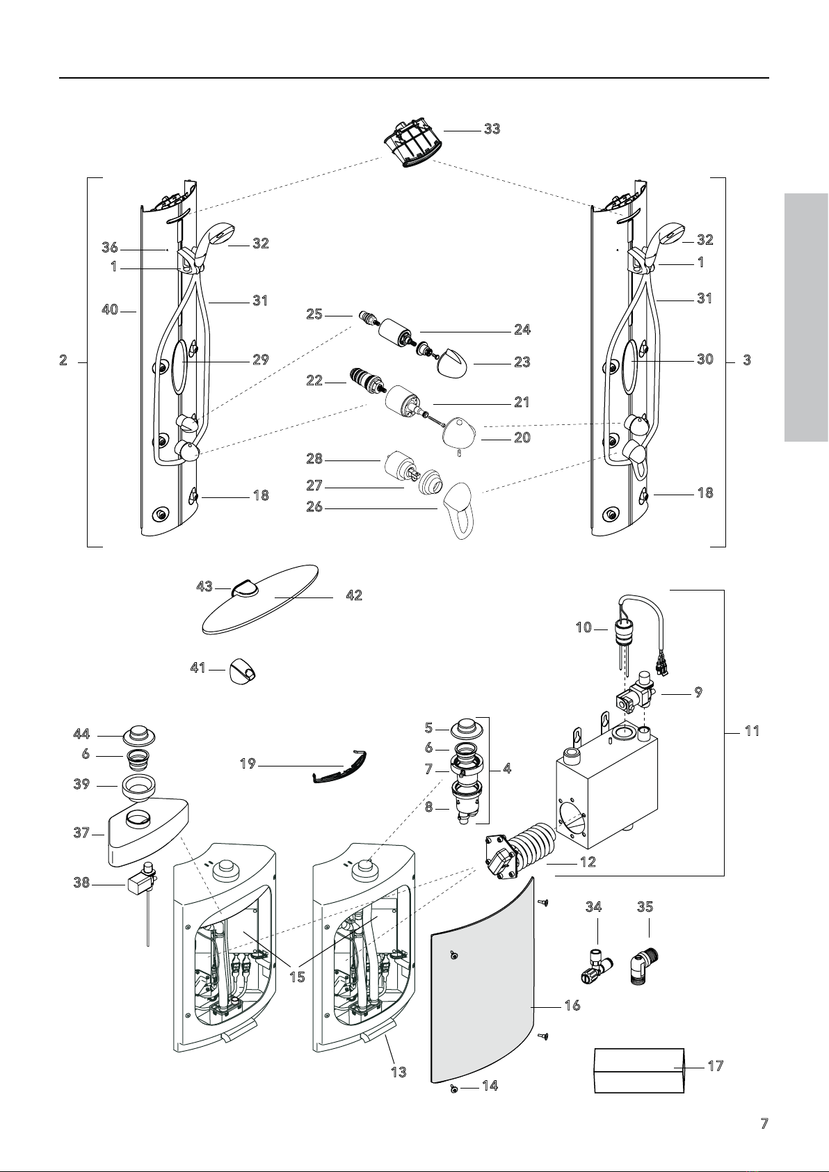
Durchflussleistung bei 3 bar:
Handbrause (1): 13,6 l/min
6 Seitenbrausen (2): 17,8 l/min
Handbrause + 6 Seitenbrausen (3):
20,6 l/min
Kopfbrause: 14,0 l/min
Schwallbrause: 20,4 l/min
Dampferzeuger:
4,1 l/h (Dampfbetrieb)
Dampferzeuger:
7,7 l/h (Dampfbetrieb + Drainage)
Funktionstüchtig ab 2 bar. Es
dürfen maximal 2 Verbraucher
zusammengeschaltet werden.
Die Dampfdusche kann nicht
in Verbindung mit hydraulisch,
elektronisch und thermisch gesteuerten
Durchlauferhitzern eingesetzt werden.
Druckunterschiede zwischen den Kalt-
und Warmwasseranschlüssen müssen
ausgeglichen werden.
Ab 14 °d (2,5 mmol/l) Ihres Wassers
ist zum Schutz des Dampfgenerators
eine Wasserenthärtungsanlage in die
Wasserzufuhr einzubauen.
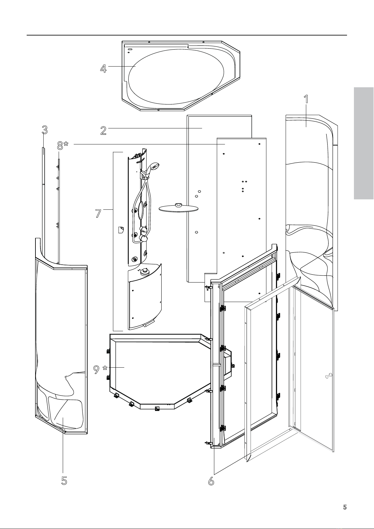
Die Dampfdusche bestehet aus
folgenden Werkstoffen:
- Kabine aus Acryl
- Kabinenrahmen aus verzinktem Stahl
- Eckschrank mit Dampftechnik aus
Acryl
- Eckprofil und Rahmen a u s
Aluminium
Mindestraumhöhe von 2250 mm not-
wendig und erforderliche Höchstbe-
lastung des Fußbodens ist 200 Kg/m²,
daher muss der Raum, in den das Pro-
dukt eingebaut wird, dem obigen ent-
sprechen.
Legende
A Leerrohr1 für Lautsprecheranschluss-
kabel.
B Leerrohr 2 mit Innen-Ø 25 mm für
Stromversorgung:
Stromversorgung 230V/N/PE/50Hz
(Länge: 3 m) vorinstallieren.
Die Absicherung muss über eine
Fehlerstrom-Schutzeinrichtung(RCD)
mit einem Bemessungsdifferenz-
strom ≤ 30 mA. erfolgen.
C Leerrohr 3 mit Innen-Ø 25 mm für
Trafokabel:
Das Leerrohr 3 für den externen
TECHNICAL DATA
Minimum flow pressure: 2 bar
Operating pressure: 2 – 5 bar
Test pressure: 16 bar
Hot water temperature: max. 70° C
Recommended hot water temp.: 60° C
Safety stop: 38° C
Flow capacity at 3 bar:
Hand shower (1): 13,6 l/min
6 body showers (2): 17,8 l/min
Hand shower + 6 body showers (3):
20,6 l/min
Over head shower: 14,0 l/min
Surge shower: 20,4 l/min
Steam generator:
4.1 l/h (steam operation)
Steam generator:
7.7 l/h (steam operation+ drain)
Functionsasfrom2bar.Only2consumers
can be switched simultaneously.
The Steam shower cannot be used
in combination with hydraulically,
electronically and thermally controlled
flow heaters.
The pressures of the cold and hot water
connections must be balanced.
Install water softening equipment in
the water inlet to protect the steam
generator as from water hardness level
14°d (2,5 mmol/l) (German Standard).
The steam shower consist of the
following materials:
- corner cabinet with steam system
made of acrylic material
- cabin made of acrylic material
- frame for cabin made of steal
profiles
- corner cabinet with steam system
made of acrylic material
- corner profile and frame montages
made of aluminium.
A minimum room height of 2250 mm is
necessary and the required maximum
floor load is 200 Kg/m², therefore the
room where the product is to be in-
stalled has to meet the requirements
mentioned above.
Legend
A Wiring conduit 1 for loudspeaker
connction cable.
B Wiring conduit 2 with internal
diameter 25 mm for power supply
cable:
pre-assemble power supply cable
230V/N/PE/50Hz (length: 3 m)
The connection must be fused via a
2-pole RCCB with a residual current
of ≤ 30 mA
C Wiring conduit 3 with internal
diameter 25 mm for transformer
DATI TECNICI
Pressione minima: 2 bar
Pressione di servizio: 2 – 5 bar
Pressione di prova: 16 bar
Temperatura acqua calda: max. 70° C
Temp. acqua calda consigliata: 60° C
Blocco di sicurezza: 38° C
Portata con 3 bar:
Doccetta (1): 12,9 l/min
6 Getti laterali (2): 17,8 l/min
Doccetta + 6 Getti laterali (3):
20,6 l/min
Soffione doccia: 14,0 l/min
Doccia ad onda piena: 20,4 l/min
Generatore di vapore:
4,1 l/h (esercizio con vapore)
Generatore di vapore:
7,7 l/h (esercizio con vapore +
drenaggio)
Funzionante a partire da 2 bar. Al massi-
mo possono essere collegate 2 utenze
contemporaneamente.
La doccia a vapore non può essere
impiegata in combinazione con scalda-
bagni istantanei idraulici, elettronici e
termostatici.
È necessario compensare le differenze
di pressione esistenti tra gli attacchi
dell'acqua fredda e quelli dell'acqua
calda.
A partire da 14°d (2,5 mmol/l) dell'acqua,
a protezione del generatore di vapore è
indispensabile montare un impianto
per la addolcificazione dell'acqua
nell'alimentazione dell'acqua.
La doccia a vapore è composta dai se-
guenti materiali:
- cabina in materiale acrilico
- telaio della cabina di profilati in
acciaio
- parete angolare con tecnologia del
vapore in materiale acrilico
- parete angolare con tecnologia del
vapore in materiale acrilico
- profilato angolare in alluminio
Altezza minima necessaria della stanza
pari a 2250 mm ed il carico massimo
richiesto per il pavimento è di 200 Kg/
m², pertanto il locale in cui si intende
installare il prodotto deve corrispondere
a quello di cui sopra.
Legenda
ATubovuoto1perilcavodicollegamento
dell’altoparlante.
BTubo vuoto 2 con Ø interno di 25 mm
per l’alimentazione elettrica:
Il cavo d’alimentazione di corrente
elettrica in dotazione con spina per
l’allacciamentodelgeneratoredivapore
alla rete (Lunghezza Max 3 m).

Pharo®WellSpring 130 29620xxx
F
11
DeutschEnglishItaliano

12
Trafoanschluss ist nur bei Kabinen
ohne Farblicht notwendig!
Der mitgelieferte Trafo muss im
Trockenbereich (Schutzzone 3)
installiert werden. Das Trafokabel
ermöglicht die Installation des
Trafos bis zu max. ca. 6 m entfernt
vom Eckschrankmodul. Der Trafo
muss jederzeit zugänglich sein. Ein
beschädigter Anschluss kann nicht
ersetzt werden. Der Trafo darf dann
nicht mehr betrieben werden.
Der Trafo wird an eine Steckdose
230V/50Hz angeschlossen und
muss über eine Fehlerstrom-
Schutzeinrichtung (RCD) mit einem
Bemessungsdifferenzstrom von
≤ 30 mA abgesichert werden.
D Leerrohr 4 für Potentialausgleich:
Potentialausgleich (Kabel mit 4 mm²
/ Länge: 3 m) vorinstallieren.
E idealer Bereich für Bodenablauf
(Ablaufleistung > 0,7 l/s)
Fidealer Bereich für Wasserzulauf aus
der Wand (nur festes- oder flexibles
Rohrmaterial verwenden).
TWW Trinkwasser warm DN15 ½“ +
bauseitig vorbereitetes Installati-
onssystem zwischenTWW-Anschluss
und Kabine.
TWK Trinkwasser kalt DN15 ½“ +
bauseitig vorbereitetes Installations-
system zwischenTWK-Anschluss und
Kabine.
Anschluss für Wasserzulauf und der
Wasserablauf sind nach den derzeit
gültigen DIN 1988/EN 1717 / DIN 1986/
EN 12056 und den örtlichen Vorschriften
zu installieren (Anschlußmuffe DN15 ½“,
bündig Fliesen).
TECHNISCHE DATEN
cable:
The Wiring conduit 3 for the external
transformer connection is necessary
only for cabins without colour light!
The transformer must be installed
in the dry area (protection zone
3). The cable provided allows the
transformer to be installed max.
approx.6 m from the corner cabinet.
The transformer must be accessible
at all times. A damaged connection
cable cannot be replaced, and the
transformer must not be operated in
this case.
The transformer will be connected
to a socket for electrical supply (230
V/50 Hz AC) and must be fused via a
2-pole RCCB with a residual current
of ≤ 30 mA.
D Wiring conduit 4 for cross-section:
pre-assemble cross section (cable
with 4 mm² / length: 3 m)
E ideal area for waste. The waste must
be able to pass 0,7 l/s.
TWW hot water (left) DN15 ½“
TWK cold water (right) DN15 ½“
Connections for water inlet and drain
have to be installed according to the
currently valid DIN 1988/EN 1717 /
DIN 1986/EN 12056 as well as local
regulations (connection sleeve DN15
½“, flush with tiles).
TECHNICAL DATA
Prevedere una scatola di collegamento
con il collegamento elettrico 230V/N/
PE/50Hz per il cavo d’alimentazione di
corrente elettrica. La protezione deve
essereeseguitaattraversouninterruttore
automaticoacorrenteresidua(RCD)con
una taratura della corrente differenziale
pari a ≤ 30 mA.
Iltubovuotadiposa3perlaconnessione
del trasformatore esterno è necessario
solamente con cabine prive di
Cromoterapia.
CTubo vuoto di posa 3 con Ø interno 25
mm per cavo del trasformatore:
Il trasformatore in dotazione deve
essereinstallatoinzonaasciutta(zonadi
protezione 3). Il cavo del trasformatore
consente di installare il trasformatore
fino ad una distanza massima di ca.
6m dal modulo armadietto angolare. Il
trasformatore deve essere accessibile
in qualsiasi momento. Non è possibile
sostituireuncollegamentodanneggiato.
In tal caso non è piùpermessoutilizzare
il trasformatore.
Il trasformatore viene collegato ad una
presadialimentazione230V/50Hzedeve
essereprotettoattraversouninterruttore
automaticoacorrenteresidua(RCD)con
una taratura della corrente differenziale
pari a ≤ 30 mA.
DTubovuotodiposa4perlacompensazione
del potenziale: preinstallare la
compensazione del potenziale (cavo
con 4 mm² / lunghezza: 3 m).
E Zona ideale per lo scarico a pavimento
(velocità di scarico > 0,7 l/s)
TWW acqua potabile calda (lato
sinistro) DN15 ½“
TWK acqua potabile fredda (lato
destro) DN15 ½“
La connessione dell‘acqua e dello scarico
devono essere predisposte seguendo le
normevalideDIN1988/EN1717/DIN1986
/ EN 12056 e in conformità alla normativa
vigentenelpaesed‘installazione(connettere
con manicotto DN 15 1/2“ a livello delle
piastrelle)
DATI TECNICI

13
Deutsch
VORWORT
Die vorliegende Anleitung ist für den
Installateurgedacht,siebeschreibt diefür
einen korrekten Einbau anzuwendenden
Systeme und Methoden.
Die Dampfduschen entsprechen den
Richtlinien und weissen daher keine
Gefahren für den Benutzer auf, falls sie
nach den vom Hersteller gelieferten
Anweisungen eingebaut, benutzt
und gepflegt werden und unter der
Bedingung, dass die elektrischen und
mechanischen Teile voll leistungstüchtig
gehalten werden.
Aus diesem Grund sind die in der
vorliegenden Anleitung verzeichneten
Anweisungen genauestens zu
befolgen.
Die Dampfduschen sind in Konformität
mit den Niederspannungsrichtlinien 73/
23/EWG, 93/68/EWG und der Norm CEI
64-8 (IEC 60364) hergestellt.
Die SchutzartistIPX5,dieNennspannung
ist 230 V/50 Hz, die Nennleistung ist 3,5
kW.
Die von der Europarichtlinie für
elektromagnetische Verträglichkeit
auferlegten Sicherheitsanforderungen
(Richtlinien 89/336/EWG, 92/31/EWG,
93/68/EWG) und die Konformität mit
der letzteren wird durch dieAnwendung
folgender europäischer Normen
gewährleistet:
EN 55014-1
EN 55014-2
EN 61000-3-2
EN 61000-3-3
EN 61000-4-2
EN 61000-4-3
EN 61000-4-4
EN 61000-4-5
EN 61000-4-11
English
FOREWORD
These instructions are intended for
the installer, they describe the systems
and methods to be used for correct
installation.
The steam showers complies with the
regulations and therefore presents
no hazards for the user, providing it is
installed, used and serviced according
to the instructions provided by the
manufacturer and with the condition
that the electrical and mechanical parts
are maintained fully operational.
Forthisreason,theinstructionscontained
here in are to be followed exactly.
The steam showers are manufactured
in conformity with the low voltage
directives 73/23/EEC, 93/68/EEC and
the CEI 64-8 (IEC 60364) standard.
The protection type is IPX5, the rated
voltage is 230 V/50 Hz, the rated power
is 3.5 KW.
The safety requirements imposed by the
European directive for electromagnetic
compatibility (directives 89/336/EEC,
92/31/EEC, 93/68/EEC) and the
conformity with the last are ensured
by the application of the following
European standards:
EN 55014-1
EN 55014-2
EN 61000-3-2
EN 61000-3-3
EN 61000-4-2
EN 61000-4-3
EN 61000-4-4
EN 61000-4-5
EN 61000-4-11
Italiano
INTRODUZIONE
Il presente manuale è destinato agli
installatori. In esso si descrivono i sistemi
ed i metodi da seguire per una corretta
installazione.
L’idrocabina rispondendo alle direttive
non rappresenta pericoli per l’operatore
se, installata, usata, mantenuta secondo
le istruzioni fornite dal costruttore e
a condizione che le parti elettriche
e quelle meccaniche siano tenute in
perfetta efficienza.
Per questa ragione occorre attenersi
scrupolosamente alle istruzioni indicate
in questo manuale.
Le docce a vapore sono prodotte in
conformità con le direttive relative alla
bassa tensione 73/23/CEE, 93/68/CEE
ed alla norma CEI 64-8 (IEC 60364).
La classe di protezione è IPX5, la
tensione nominale
è 230 V/50 Hz, la potenza nominale è
di 3,5 kW.
Il rispetto delle disposizioni di sicurezza
emesse dalla direttiva europea relativa
alla tollerabilità elettromagnetica
(direttive 89/336/CEE, 92/31/CEE, 93/
68/CEE) e la conformità con quest'ultima
viene garantita attraverso l'applicazione
delle seguenti norme europee:
EN 55014-1
EN 55014-2
EN 61000-3-2
EN 61000-3-3
EN 61000-4-2
EN 61000-4-3
EN 61000-4-4
EN 61000-4-5
EN 61000-4-11

14
IN DER ANLEITUNG VERWEN-
DETE SYMBOLE
In der vorliegenden Einbauanleitung
und an einigen Stellen auf dem Produkt
selbst befinden sich Symbole, die hier
unten beschrieben werden.
ÜBLICHE SYMBOLE UND IHRE
BESCHREIBUNG.
ACHTUNG STROMSCHLAGGEFAHR
Meldet dem betreffenden Personal,
dass der beschriebene Vorgang,
falls nicht unter Einhaltung der
Sicherheitsvorschriften ausgeführt, das
Risiko eines elektrischen Schlags birgt.
ACHTUNG ALLGEMEINE GEFAHR
Meldet dem betreffenden Personal,
dass der beschriebene Vorgang,
falls nicht unter Einhaltung der
Sicherheitsvorschriften ausgeführt, das
Risiko von Körperverletzungen birgt.
ACHTUNG,
ZWEI PERSONEN NOTWENDIG!
Bezeichnet eine bestimmte Vorgehens-
weise. Wenn diese nicht eingehalten
wird kann das Produkt oder etwas in
seiner Umgebung beschädigt werden.
(Die Montage muss von zwei Personen
durchgeführt werden)!
ANMERKUNG
Weist das betreffende Personal
auf Informationen hin, deren
Nichtbeachtung zu leichten Personen-
oder Produktschäden führen kann.
HINWEIS
Weist das betreffende Personal auf
Informationen hin, deren Inhalt wichtig
ist und berücksichtigt werden soll.
HYDRAULISCHER INSTALLATEUR
Fachtechniker, der imstande ist, das
Produkt unter normalen Bedingungen
einzubauen und Eingriffe wie
Einstellungen, Wartungs- und
notwendige Reparaturarbeiten an
mechanischen Teilen auszuführen. Er ist
nicht befähigt, Eingriffe an elektrischen
Anlagen auszuführen, wenn diese unter
Spannung stehen.
SYMBOLS USED IN THE INSTRUC-
TIONS
The symbols described below appear
in these Installation Instructions and in
some locations on the product itself.
SYMBOLS USED AND THEIR
DESCRIPTION.
ATTENTION RISK OF ELECTRIC
SHOCK
Informs the personnel concerned that
the process described, unless performed
in compliance with the safety rules,bears
the risk of electric shock.
ATTENTION GENERAL HAZARD
Informs the personnel concerned that
the process described, unless performed
in compliance with the safety rules,bears
the risk of injury.
ATTENTION,
TWO PERSONS REQUIRED!
Describes a specific procedure. If this
procedure is not observed, the prod-
uct or objects within its environment
may be damaged. (The steam shower's
installation must be carried out by two
persons)!
COMMENT
Informs the personnel concerned of
information which, if not observed, can
cause minor injuries or damage.
NOTE
Informs the personnel concerned of
information with important contents to
be observed.
INSTALLER
Specialist technician capable of
installing the product under normal
conditions and performing settings,
maintenance and necessary repair work
on mechanical parts.He is not authorised
to make interventions on live electrical
equipment.
SIMBOLI UTILIZZATI NEL MANU-
ALE
Nel presente manuale di istruzioni di
montaggio si trovano dei simboli alcuni
dei quali si trovano applicati in alcuni punti
del prodotto stesso. In questa parte della
documentazionesiprocedealladescrizione
del significato di questi simboli.
SIMBOLI CORRENTI E DESCRIZIONE DEL
LORO SIGNIFICATO.
ATTENZIONE PERICOLO DI SCOSSA
ELETTRICA
Segnala al personale interessato che
l'operazione descritta può comportare
il rischio di una scossa elettrica se non
eseguita nel pieno rispetto delle norme
di sicurezza.
ATTENZIONE PERICOLO GENERALE
Segnala al personale interessato che
l'operazione descritta può comportare il
rischio di seri incidenti se non eseguita nel
pieno rispetto delle norme di sicurezza.
Attenzione:
sono necessarie due persone!
Indica un determinato procedimento.
Se non viene rispettato, il prodotto o
oggetti nelle sue vicinanze possono
essere danneggiati (il montaggio della
doccia a vapore deve essere eseguito
da due persone)!
AVVERTENZA
Richiama l'attenzione del personale
interessato su informazioni che in caso di
inosservanza possono comportare leggeri
danni a persone ed al prodotto.
NOTA BENE
Segnala al personale interessato
informazioni con un contenuto importante
che deve essere tento in considerazione.

15
Deutsch
ELEKTRISCHER INSTALLATEUR
Fachtechniker, der imstande ist, das
Produkt unter normalen Bedingungen
einzubauen. Er ist für alle Eingriffe
elektrischer Art wie Einstellungen,
Wartung und Reparaturen zuständig.
Er ist imstande, unter Spannung in
Schaltschränken oder elektrischen
Dosen zu arbeiten.
ACHTUNG VOR HANDVERLETZUNG
Hände weg von Stellen, die dieses
Warnzeichen tragen! Es besteht die
Gefahr, daß die Hände eingequetscht,
eingezogen oder anderweitig verletzt
werden können.
English
ELECTRICIAN
Specialist technician capable of installing
the product under normal conditions. He
is responsible for all electrical work, such
as setting,maintenance and repairs. He is
capable of working in energized control
cabinets or on electrical sockets.
CAUTION HANDINJURY
Hands away by sites, which are marked
with this symbol!Caution! Hands can be:
squash in, retract or otherwise injured.
Italiano
INSTALLATORE IDRAULICO
Tecnico specializzato in grado di installare il
prodottoinnormalisituazioniedadeseguire
interventi di registrazione, di manutenzione
e di necessari lavori di riparazione su parti
meccaniche. Egli non è autorizzato ad
eseguire interventi su impianti elettrici che
si trovino sotto tensione.
INSTALLATORE ELETTRICO
Tecnico specializzato in grado di installare
il prodotto in normali condizioni di lavoro.
Tra le sue competenze rientrano tutti gli
interventi ditipoelettricocomeregistrazioni,
manutenzione e riparazioni. Egli è in grado
di intervenire in quadri elettrici ad armadio
oppure su prese per la corrente che si
trovino sotto tensione.
FARE ATTENZIONE A NON FERIRSI
ALLA MANO
Non mettete le mani in posti sui quali si
trova questo segnale di pericolo! C’è il
rischio che le mani vengano schiaccia-
te, tirate dentro oppure o che possano
essere ferite in altro modo.

16
Vor dem Einbau des Produktes muss
geprüft werden, ob der Fußboden,
auf dem die Dampfkabine installiert
wird, ausreichend nivelliert ist, ob
er das Gewicht tragen kann, und ob
alle technologischen Ausrüstungen
vorhanden sind.
Vor der Ausführung von Reinigungs-
und Wartungsarbeiten muss das
Produkt auf den Energiezustand Null
gebracht werden, d. h. Fehlerstrom-
Schutzeinrichtung (RCD) auslösen.
Der Einbau von elektrischen
Vorrichtungen (Steckdosen, Schalter,
Lampen, usw.) im Badezimmer bzw. im
Installationsraum des Geräts muss nach
den diesbezüglich gültigenVorschriften
erfolgen.
ACHTUNG:
Kein essigsäurehaltiges Silikon
verwenden.
Durch den Gebrauch von essigsäure-
haltigem Silikon könnten die Acryl- bzw.
Metallteile der Duschkabine beschädigt
werden.
FürdasVerfugenzwischendenElementen
empfehlen wir die Verwendung
von pilzhemmendem Sanitärsilikon.
Dennoch kann es unter Umständen zu
Verfärbungen des Silikondichtstoffes
kommen.
Falls durch Reinigung der Fugen die
Verfärbung nicht zu entfernen ist,müssen
die Silikonfugen ausgetauscht werden.
Silikonfugen sind Wartungsfugen und
unterliegen nicht der Gewährleistung.
ACHTUNG (nur für wannenlos Version):
Ausschliesslich chemikalienfeste Boden-
fliesen oder Duschwanne einsetzen (z.B.
Stahlemail).
Durch austretenden Duftstoff wird ein
nicht chemikalienfester Untergrund
beschädigt.
Die Dampfdusche darf in ihrer
Bauart nicht verändert werden. Nur
Originalersatzteile verwenden.
Stromversorgung:
Der Elektroanschluss darf ausschließlich
vom Elektrofachmann, Ihrem Elektro-
Installateur durchgeführt werden.
Die gesamte Stromversorgung
erfolgt über einen 230V/N/PE/
50Hz Wechselstromanschluss und
muss über eine Fehlerstrom-
Schutzeinrichtung (RCD) mit einem
Bemessungsdifferenzstrom von ≤ 30 mA
abgesichert werden.
SICHERHEITSVORSCHRIFTEN
Before installing the product check
whether the floor on which the steam
shower cabin is to be installed has
been levelled sufficiently and whether
it can carry the weight and whether all
technological equipment is available.
Set the product to the zero energy state
prior to any cleaning and repair work,i.e.
trigger the RCCB protective switch.
Install electrical devices (sockets,
switches, lamps, etc.) in the bathroom
or in the equipment installation room
according to the relevant regulations.
ATTENTION:
Do not use silicone containing acetic
acid!
Acrylic or metal parts of the shower cabin
can be damaged by the use of silicone
containing acetic acid.
Seals
Fortheflexiblesealsbetweentheelements
we advise to use schimmelwerende
silicone kit. Despite this, and dependant
on circumstances,colorchanges in the kit
can happen. If cleaning does not bring
the wanted result, the seals have to be
exchanged. Renewing is not within our
warranty
Caution (nur für wannenlos-Version):
Use only chemical-resistant floor tiles or
a shower tub (e.g. steel enamel).
A non chemical-resistant base is dama-
ged by emitted scents.
The steam shower’s construction must
not be changed. Only original compo-
nents may be used.
Power supply:
The electrical connection may only be
carried out by an electrician, i.e. your
electrical installer. The entire power
supply is realized via a 230V/N/PE/50Hz
AC connection and must be fused via a
2-pole RCCB with a residual current of
≤ 30 mA.
For electrical installation, all applicable
VDE, country-specific and EVU
regulations in their respectively
valid versions must be observed.
All installation and inspection works
must be carried out by an approved
electrician and in accordance with VDE
0100 Part 701. All works at the steam
shower may only be carried out in a de-
energized state!
SAFETY PRECAUTIONS
Prima di procedere all‘installazione
del prodotto ci si deve accertare se il
pavimento di posa sia sufficientemente
livellato, se è adatto a sostenere il peso
previsto e se sono disponibili tutte le
previste apparecchiature tecnologiche.
Primadiprocedereadinterventi dipulizia
e di manutenzione è necessario mettere
il prodotto allo stato energetico zero,
cioè, aprire l'interruttore di massima.
L'installazionedidispositivielettrici(presa
per la corrente, interruttori, lampadine,
ecc.) nel bagno oppure nel locale da
installazione dell'apparecchiatura deve
essere eseguita in conformità con le
relative prescrizioni in vigore.
ATTENZIONE:
Non utilizzare silicone contenente acido
acetico.
Utilizzando silicone contenente acido
acetico vi è il pericolo di danneggiare
parti in materiale acrilico oppure parti
metalliche della cabina doccia.
Per la sigillatura tra gli elementi
raccomandiamo l’uso di silicone
antimuffa per sanitari. Ciò nonostante
si possono verificare macchie o
scolorimenti del silicone sigillante. Nel
caso in cui gli scolorimenti o macchie
non si lasciano eliminare pulendo
semplicemente i giunti, è necessario
sostituirli. I giunti di silicone sono giunti
soggetti a manutenzione e non fanno
parte della garanzia concessa.
Attenzione (nur für wannenlos-Versi-
on):
Impiegare esclusivamente piastrelle da
pavimento resistenti a prodotti chimici
oppure vasca per doccia (p. es. smalto
d'acciaio).
Un fondo base non resistente a prodotti
chimici viene danneggiato da sostanze
odoranti fuoriuscenti.
La struttura della doccia con vapore
non deve essere modificata. Usare solo
ricambi originali.
Alimentazione elettrica:
L’allacciamento elettrico deve essere
eseguito solo da un tecnico (elettricista
esperto). L’intero sistema viene
alimentato a tensione alternata a 230V/
N/PE/50Hz e l’impianto deve possedere
un interruttore di sicurezza per correnti
di guasto (salvavita) bipolare con
corrente di apertura di ≤ 30 mA.
PRESCRIZIONI DI SICUREZZA

17
Deutsch
Bei der Elektro-Installation sind die
entsprechenden VDE-, Landes- und
EVU-Vorschriften in der jeweils gültigen
Fassung einzuhalten. Die Installations-
und Prüfungsarbeiten sind von einem
zugelassenen Elektrofachmann
auszuführen,unter Berücksichtigung von
VDE 0100 Teil 701. Sämtliche Arbeiten
an der Dampfdusche dürfen nur im
spannungsfreien Zustand vorgenommen
werden!
Lautsprecher
Beim Anschluss an eine externe
Stereoanlage ist folgendes zu
beachten:
Die Lautsprecher dürfen nur an Hifi-
Anlagen angeschlossen werden, die
die EG Niederspannungsrichtlinie
2006/95/EG sowie die Vorgaben der
DIN EN 60065 erfüllen. Die maximale
Ausgangsspannung der Hifi-Anlage
muss unter 25 V pro Kanal liegen. Die
maximale Leistung der Lautsprecher
beträgt 30 W pro Kanal.
Hinweise zur Verwendung
In ihrer Bewegung eingeschränkte
ältere und behinderte Personen
sollten bei der Nutzung der
Dampfdusche besondere Sorgfalt
walten lassen.
Falls Sie gesundheitliche Beden-
ken haben, setzen Sie sich mit
Ihrem Arzt in Verbindung.
Beispiele zur Nichtverwendung
Die Dampfduschen dürfen nicht
im öffentlichen Bereich eingesetzt
werden.
Kinder dürfen nicht unbeaufsich-
tigt die Dampfdusche benutzen.
•
•
•
•
English
Speaker
Observe the following when connecting
to external stereo equipment:
The built in loudspeaker system should
be connected only to an audio amplifier
which meets with the request of the EG
low voltage guideline 2006/95/EG as
well as the security request of DIN EN
60065. The max. peak voltage ouput of
the amplifier must be below 25 V. The
maximum peak power output of the
amplifier must be under 30 W.
Tip for using
People who are constricted in
their action should be use the
steam cabine special diligence
Please contact your doctor if you
have health concerns.
Examples for non-using
the steam cabines may not be
used in public areas.
Children must not be left unatten-
ded in the steam cabine.
•
•
•
•
Italiano
Per l’impianto elettrico si devono
rispettare le norme CEI e dell’azienda
elettrica vigenti.
I lavori di installazione e di collaudo
devono essere svolti da un tecnico
autorizzato. Qualsiasi intervento sulla
doccia a vapore va eseguito solo dopo
aver staccato la tensione elettrica!
Con Altoparlante
In caso di collegamento con un impianto
stereofonico esterno è necessario
tenere presente quanto segue:
Il sistema di altoparlante incorporato
può essere collegato solo ad un
amplificatore audio che risponda sia
ai requisiti della direttiva EG relativa
al basso voltaggio 2006/95/EG che ai
requisiti di sicurezza DIN EN 60065.
L’uscita massima dell’amplificatore deve
essere inferiore ai 25 Watt per canale.
Esempi di uso
persone che hanno limitazioni
motorie dovrebbero usare la vas-
ca con molta attenzione.
consultate il vostro medico se
avete qualche malattia.
Esempi di uso improprio
la vasca idromassaggio non può
essere usata in luoghi pubblici.
I bambini non devono essere
lasciati incustoditi nella vasca.
•
•
•
•

18
BENÖTIGTES WERKZEUG
Sich vor dem Einbau mit folgendem
Werkzeug ausrüsten:
ASchlagbohrmaschine
BBohrer Ø 8 mm
CInbusschlüssel SW 2,5mm
DInbusschlüssel SW 4 mm
E Inbusschlüssel SW 5 mm
FMaulschlüssel SW 13 mm
GMaulschlüssel SW 17 mm
HMaulschlüssel SW 19 mm
IMaulschlüssel SW 20 mm
JMaulschlüssel SW 24 mm
KSchlitzschraubendreher
Lkleiner Schlitzschraubendreher
MWasserwaage
NMesser
OBleistift
PMeterstab
QBockleiter
R Silikon
ANMERKUNG
Ausschließlich essigsäurefreies Silikon
verwenden
REQUIRED TOOLS
Make sure the following tools are
available before installation:
AHammer drill
BDrill 8 mm diameter
CAllen wrench SW 2,5 mm
DAllen wrench SW 4 mm
EAllen wrench SW 5 mm
FSpanner SW 13 mm
GSpanner SW 17 mm
HSpanner SW 19 mm
ISpanner SW 20 mm
JSpanner SW 24 mm
KSlotted screwdriver
L Small slotted screwdriver
MSpirit level
NKnife
OPencil
PMetre rule
QSteps
RSilicone
COMMENT
Only use silicone free from acetic acid
UTENSILI RICHIESTI
Prima di procedere al montaggio,
procurarsi i seguenti attrezzi:
Atrapano battente
Bpunta Ø 8 mm
Cchiave a brugola misura 2,5 mm
Dchiave a brugola misura 4 mm
Echiave a brugola misura 5 mm
Fchiave fissa misura 13 mm
Gchiave fissa misura 17 mm
Hchiave fissa misura 19 mm
Ichiave fissa misura 20 mm
Jchiave fissa misura 24 mm
Kcacciavite a taglio
L piccolo cacciavite a taglio
Mlivella
Ntaglierino
Omatita
Pmetro
Qscala doppia
Rsilicone
AVVERTENZA
Utilizzare esclusivamente silicone privo
da acido acetico

19
AB
F
C
M
KL
E
N
D
J
I
H
G
Q
P
O
R
DeutschEnglishItaliano

20
Das Seitenelement 1 an den Einbauort
bringen.
1. Die Abstandshalter Aauf die
seitlichen Klemmbügel schieben.
Die Abstandhalter müssen zwischen
den beiden Elementen positioniert
werden!
2. Die Zylinderschraube B(M5x20)
in das Gewinde am Klemmbügel
eindrehen und anziehen.
Die Blechschraube C(Ø4,2x13)
und Unt erlegscheibe D(5,3) in den
Rahmen eindrehen und anziehen.
MONTAGE ACRYLELEMENTE
WELLSPRING 130
INSTALLATION OF ACRYLIC
ELEMENTS WELLSPRING 130
Bring the side panel 1 to the installation
site
1. Push on spacer Ato the clamping
yokes on side.
The spacers must be positioned between
both elements!
2. Screw in cylinder head screw B
(M5x20) into the worm of clamping
yoke and tighten it.
Screw in self-tapping screw C
(Ø4,2x13) and washer D(5,3) into
the frame. Tighten it.
Portare l‘elemento angolare sul luogo
di montaggio e posarlo sul bordo del
piatto doccia.
1. Inserire i distanziatori Asui morsetti
laterali.
I distanziatori devono essere
posizionati tra i due elementi!
3. Avvitare la vite a testa cilindrica E
(M5x20) nella filettatura del morsetto
e stringerla.
Avvitare la vite autofilettante C
(Ø4,2x13) e la rondella D(5,3) nel
telaio e stringere.
MONTAGGIO DEGLI ELEMENTI
ACRILICI WELLSPRING 130
Table of contents
Popular Other manuals by other brands

Bubble Magus
Bubble Magus Curve Elite Series user manual

Omron
Omron V680S-HMD63-EIP instruction sheet

Allen-Bradley
Allen-Bradley E300 installation instructions

Whelen Engineering Company
Whelen Engineering Company TIR3 installation guide

Master Halco
Master Halco PostMaster Installation guidelines

NEC
NEC NEC Indoor Cabinet Installation