phase II+ UTG-4000 User manual

ModelNo.UTG‐4000
www.phase2plus.com
283 Veterans Blvd
Carlstadt, NJ. 07072
(201) 933-6300
www.phase2plus.com
21IndustrialAveUpperSaddleRiver,NJ.07458
P(201)962‐7373 F(201)962‐8353
E‐mail:info@phase2plus.com

CONTENT
1. GENERAL INTRODUCTION3
1.1 CONSTRUCTION OF THE GAGE........3
1.2 STANDARD CONFIGURATIONS.........3
1.3 OPTIONAL CONFIGURATIONS..........3
1.4 SPECIFICATIONS.............................4
1.5 MAIN FUCTIONS..............................5
2. KEYBOARD FUCTIONS5
3. MEASURING THE THICKNESS6
3.1 PRESET THE MATERIAL’S VELOCITY6
3.2 PRESET OTHER SPECIFICATIONS....7
3.3 CALIBRATION.................................8
3.4 DISPLAY MODES.............................9
3.5 ADJUSTING THE SPECIFICATIONS IN A-SCAN MODE
........................................................11
3.6 REAL CASES ANALYSIS................12
4.CARE AND MAINTENANCES16
4.1 POWER SOURCE INSPECTION......17
4.2.......................................Maintenance
4.3 Service / Support..........................17
APPENDIX: SOUND VELOCITIES OF COMMON MATERIALS17

1. GENERAL INTRODUCTION
UtilizingliveA‐scanandtimebasedB‐scanforabsolutecorrectness,thisnewstateoftheart
thicknessgaugeispackedwithusefulfeaturesallowinguserstobeconfidentofthedisplayedvalueson
themostcriticalofapplications.Thismulti‐functionalunitofferseverythingfrombasicmeasurement,
ScanwithMin/Maxviewing,GO/NOGOdisplayandAdjustableSoundVelocity.Thisdynamicsonicgauge
isde s i g n e d tomeasurethethicknessofmetallicandnon‐metallicmaterialsincriticalsituationsthat
ordinarythicknessgaugescouldn’tdo.
TheUTG‐4000willaccuratelydisplayreadingsineitherinchormillimeterafterasimplecalibrationto
aknownthicknessorsoundvelocity.
1.1CONSTRUCTIONOFTHEGAGE
1.2STANDARDCONFIGURATION
Qty
ThicknessGauge 1
5MHzPROBE 1
AABatteries 2
2ozCouplantGel 1
RuggedCarrycase 1
OperationManual 1
1.3OPTIONALACCESSORIES
High‐temperatureprobe Castironprobe
SmallProbe(6mm) MiniProbe(4mm)
Probecable 5‐Stepblock
IMPORTANT!
TheUTG‐4000isamulti‐functionalthicknessgaugethatallowstheusertremendouscontroloverthefunctionalityandperformance
ofthisinstrument.Althoughthis providestheuser withcontrolandversatilityfornumerousapplications,italsorequiresthatthe
userbefamiliarwiththefunction,operationandwaveforminterpretationoftheinstrumentaswell.
Itisrecommendedthattheuserspendasufficientamountoftimeworkingwiththisinstrumentpriortofielduse.
Responsibilityforproperuserestssolelywiththeuserofthisinstrument.

1.4SPECIFICATIONS
OperatingPrincipleUltrasonic Pulse/Echo and Echo to Echo
methodwithdualelementprobe
Displaytype2.4”ColorScreen
Resolution0.001”,.01”/0.01mm(Inch/Metricselectable)
MeasuringRange0.02‐20.0” Dependantuponprobe&material
Repeatability+/‐.001” (+/‐0.05mm)
Soundvelocityrange0.0197‐0.3937in/us (500‐9999m/s)
MeasuringError:0.001” (upto0.393”steel)
+/‐0.5%H+0.0003”(over0.393”steel)
H=actualvalue
DisplayModes:DigitalThicknessReadout
A‐scanorB‐scan
Min/MaxCapture
Diff‐Value/Reduction
V‐PathCorrectionAutomatic
UpdateRateSelectable:4Hz,8Hz,16Hz
Refreshrate4/second
AlarmSettingsMin/MaxAlarm
Dynamicwaveformcolorchangeonalarm
Operatingtemperature14‐122ºF (‐10ºC‐+50ºC)
AutoShut‐OffAfter5minutes
Powersupply3vAAalkalinebatteries(2pc)
OperatingTimeApprox.36hours
Dimensions6.02”x2.99”x1.45” (153x76x37mm)
Weight9.9oz (280g)

1.5MAINFUCTIONS
1.User‐friendlyinterface
2.OptionalA‐scanwaveformdisplay
3.TimebasedB‐scanfunctiondisplayscrosssectionoftestpiece
4.Differentcouplingstatusshowingindifferentcolors
5.Thicknessalarm:automaticalarmwhentheresultexceedsthepresetthicknessrange
6.Limitsvaluemode:Displaystheminimumandmaximumvalueswhenmeasuring
7.Differencemode:gettingthedifferencebetweentheactualvalueandthenormalvalueaswellasthe
percentage
8.Inch/MetricConversion
9.Extralargememory:upto100,000values&1000waveforms
10.SelectableResolution:0.001”,0.01”or.01mm
11.Optionalrectificationmode:RF,fullwave,half+,half‐
12.Optionalwaveform:outlinemodeorfilledmode
13.Approx.batteryLife:35hours
2.KEYBOARDFUCTIONS
ThekeyboardfortheUTG‐4000consistsof3virtualfunctionkeys(P1,P2,P3),fourdirectionkeys
andtwospecializedfunctionkeys(MandCAL/ON).
Seethefollowingillustration(2.1)
2.1KEYBOARDFUCTIONILLUSTRATION
P1,P2,P3operatethefunctionshownon
thedisplayjustaboveeachrespective
button.
“M”keyopensupthemain
interfaceallowingyoutochoosea
configurationorreturntothe
maintestingscreen.The
4‐directionkeysallowyouto
togglethroughtheinterface

3.MEASURINGTHICKNESS
3.1SoundVelocityCalibration
In order for the gauge to make accurate measurements, it must besettothecorrectsoundvelocityforthe
materialbeingmeasured.Differenttypesofmaterialhavedifferentinherentsoundvelocities.Ifthegaugeisnotsetto
thecorrectsoundvelocity,allofthemeasurementsthegaugemakeswillbeerroneousbysomefixedpercentage.The
One‐Pointcalibrationisthesimplestandmostcommonlyusedcalibrationprocedureoptimizinglinearityoverlarge
ranges. The Two‐pointcalibration allows for greater accuracy over small ranges by calculating the probe zero and
velocity.
Note:OneandTwopointcalibrationsmustbeperformedonmaterialwiththepaintorcoatingremoved.Failureto
removethepaintorcoatingpriortocalibrationwillresultinamultimaterialvelocitycalculationthatmaybedifferent
fromtheactualmaterialvelocityintendedtobemeasured.
Calibrationtoaknownthickness
Note:Thisprocedurerequiresasamplepieceofthespecificmaterialtobemeasuredwithaknownthickness
value.Thispartshouldbemeasuredwithacaliperormicrometer.
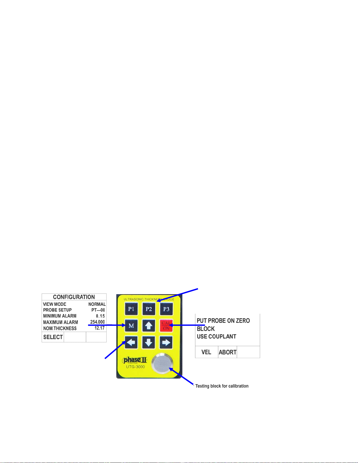
1) Performatestonthebuilt‐intestblocktoverifyunitisfunctioningproperly
2) Applycouplanttoyoursamplepiece.
3) Pressthetransduceragainstyoursamplepiece,makingsurethatthetransducersitsflatagainstthesurface
ofthesample.Thedisplayshouldshowa“whitecolored”thicknessvalue.
4) Havingachievedastablereading,removethetransducer.Ifthedisplayedthicknesschangesfromthevalue
shownwhilethetransducerwascoupled,repeatstep3.
5) PresstheCAL/ONbuttontoenterCalibrationmode.OnthebottomleftcornerofthedisplayitwillshowVEL.
PressthevirtualP1buttontoentervelocitysetting.
6) Pressthetransduceragainstthesamplepiece,makingsurethatthetransducersitsflatagainstthesurfaceof
thesample.ThedisplayshouldshowsomethicknessvalueintheTopLeftCornerasT=X.XXX.
7) Whileholdingtheprobeonyoursample,usethe4‐Arrowbuttonstochangethevelocityvalueuntilyousee
theT=theactualthicknessofyourpart.
8) PressP2(Done)buttontosavethesetting.
9) Youcannowbegintestingyourapplication(s)ofthissamematerial.
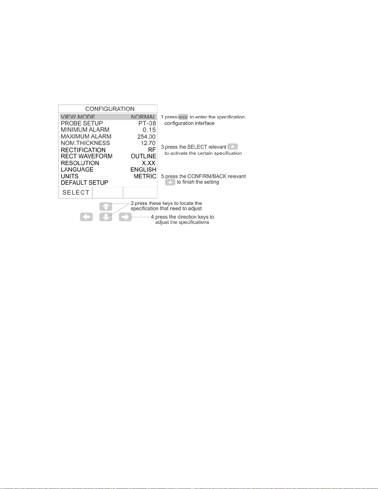
3.2.Adjustthevelocitydirectlyifthematerialvelocityisknown.Seeillustrationbelow.

3.2PRESETOTHERSPECIFICATIONS
Press “M”toentertheuserinterface,whichallowsyoutoselectandadjust options like VIEW
MODE, PROBE SETUP, MINIMUM ALARM, MAXIMUM ALARM, NORMAL THICKNESS, MINIMUM of
B‐SCAN, MAXIMUM of B‐SCAN, RECTIFICATION, RECTIFICATION WAVEFORM, RESOLUTION,
LANGUAGE,UPDATERATES,UNITS,ANDDEFAULTSETUP.Seethefollowingfigure:
3.2MenuSelections
VIEWMODE:normalmode,differencemodeandlimitscanningmode.
PROBESETUP:PT‐10/PT‐08(normalprobe),PT‐06(smallprobe),PT‐04(miniprobe),GT‐12(high‐temperature
probe),andZT‐12(castironprobe).
MINIMUMALARM: set the minimum thickness alarm value. The result will be displayedinrediftheactual
thicknessislessthantheminimumvaluepreset.
MAXIMUMALARM: set the maximum thickness alarm value. The result will be displayedinrediftheactual
thicknessismorethanthemaximumvaluepreset.
NORMALTHICKNESS:setthenormalthickness.Therealconcreteapplicationwillbe introduced in the
DIFFERENCEMODE.
MINIMUMofB‐SCAN:setminimumthicknessforB‐scan
MAXIMUMofB‐SCAN:setmaximumthicknessforB‐scan
RECTIFICATIONMODE: RF, full wave, half ‐, half +. RF describes the complete echo waveform; full wave
indicatesthehalf+echoandtheoverturnedhalf‐echo;half–meansputtingoffthehalf+echoandturnthehalf
–overto+;half+meansputtingoffthehalf–echoandonlyleftthehalf+echo.
RECTIFICATIONWAVEFORM:outlinemodeandfillmode.
RESOLUTION:SelectableResolution:0.001”,0.01”or.01mm
LANGUAGE:theinterfacelanguage:ChineseorEnglish.

UNITS:Selectable:mmorinch.
UPDATERATE:Updatetherateofmeasurementresult.Optional4,8or16Hz.
AUTOPOWERDOWN:Thedevicecanbesettoshutoffafter5,10,20minutesofinactivity.IfsettoOFFthenthe
Cal/ONbuttonwillpowertheunitonoroffwhenpressed.
DELETEALLFILES:Emptyallmemoryofvaluesandwaveforms.
DEFAULTSETUP:Bringsunitbacktooriginalfactorysettings
3.3CALIBRATION
Before using the UTG‐4000, calibrating the gage as well as the probe is necessary. See the following
steps:
3.3CALIBRATIONSTEPILLUSTRATION
1.Adjustthesoundvelocityto0.233”or(5900metric)accordingtothemethodinchapter3.1.
2.Afterturningonthegage,presstoenterthecalibration interface. The screen shows PUT
PROBEONZEROBLOCKUSECOUPLANT.
3.Spreadthecouplantaccordingtothepresentation,thenputtheprobeonthezeroblockandmakeit
coupledcompletelyuntilthescreenshowsACQUIRINGPLEASESTAYCOUPLED.
4.Holdafewseconds,andthescreenwilldisplayPROBEZEROCOMPLETEREMOVEPROBEFROMZERO
BLOCK. Remove the probe from the zero block and the display returns backtothemeasuring
interfaceautomatically. Thedisplayshouldshow0.157”or4mm.Ifanyothervaluesappear
thenyoumustadjustthesoundvelocityaccordingly.
5.Duringthecalibrationprocess,pressthe“P2”buttontoABORTatanytimetostopthecalibration
processandtheunitwillgobacktothemeasuringinterface.

3.4DISPLAYMODES
Therearethreemeasuringinterfacedisplaymodes:normalmode,A‐scanmodeandB‐scanmode.
AndtherearethreedisplaymodesofNormal interface:Thethicknessvaluemode,Difference/rateof
reduction measurement mode, MAX/MIN measurement mode. Select this in “VIEW MODE” of
configuration.
ATTENTION:Whentheprobeisproperly“coupled”tothesurfaceoftheobjectbeingtested,the
valueonthedisplaywillbeshowninWHITE.Ifnotcoupledproperlythenthevalueswillbeshownin
GREEN.WhenthevaluesexceedtheupperorlowerlimitsettingthenthevalueswillbeshowninRED.
THICKNESSVALUEMODE:Thisinterfaceshowsthevelocityofmaterial,thepresentthicknessvalue
andunit.
3.4NORMALMODEINTERFACE
1—thepresentthicknessvalue 2—unit 3—materialvelocity4—batterypower 5—A‐scaninterface
DIFFERENCE/RATE‐OF‐REDUCTIONMODE: This interface shows the measured value, the preset
nominalthicknessvalue,thedifferencebetweenthemeasuredvalueandthepresetvalueandtheratio
betweenthedifferenceandthenormalvalue.Beforeusingthismode,presettingthenominalthickness
isneeded.

3.5DIFFERENCEMODEINTERFACE
1—the difference between the normal value and the preset value 2—the ratio between the
differenceandthenominalvalue 3—thepresentthicknessvalue 4—thenormalvalue
5—differencesignal 6—materialvelocity 7—batterypower8—A—scaninterface
LIMITSVALUESCANNINGMODE:thismodeallowsthecustomertotest the thickness of material
continuouslyandtoshowtheupper/lowerlimitsafterthetests.Itshowstheminimumandmaximum
valuesduringthetestsaswellasthepresentthickness.PresstheRESETbuttontogetthelimitswhen
measuringthethickness.
3.6LIMITSVALUEMODEINTERFACE
1—thepresentthicknessvalue 2—themaximumvalue 3—theminimumvalue 4—unit
5—materialvelocity 6—batterypower7—A—scaninterface 8—reset

A‐scanmode:ThisinterfaceallowsyoutoseethepresentthicknessvalueandtheA‐scanwaveformat
thesametime.Therightsideoftheinterfaceisthespecificationadjustingarea,whichcanbeadjusted
foramorepreciseresult.Thedetailedinstructionscanbeseeninchapter3.5.
3.7A‐SCANMODEINTERFACE
1—waveformdisplayarea2—gate 3—materialvelocity4—the present highlighted
specification 5—measuringpoint(thefirstpointofintersectionbetweenthewaveformandthegate)
6—thepresentthicknessvalue7—theblankconfines
8—therangeconfines 9—thespecificationadjustingarea 10—highlightedsignal
11—digitmode 12—specificationswitch 13—batterypower
ATTENTION:Whentheprobeandtheobjectarenotcompletelycoupled,theletters in the various
interfacesareshowninGREEN,whenproperlycoupled,theyaredisplayedinWHITEcolorandwhen
theeithertheupperorlowerlimitsareexceeded,theletterswillbedisplayedinREDcolor.
3.5ADJUSTINGTHESPECIFICATIONSINA‐SCANINTERFACE
IntheA‐scaninterface,presstheP3buttontohighlightthevaluetobeadjusted.Thenpressthe
directionkeystoadjustthevalues.Upanddownkeysareusedforsmallincrements,whileleftandright
forlargerincrements.
GAIN—adjustthesensitivityofthegagewithunitdB.Thelargerthegainis,thehigherthesensitivityis.
Thegainrangesfrom8to55dB.
HelpfulHints:Whentestingflatparts,thegainshouldbelow.Aluminumandcastaluminumshouldalso
uselowgain.Steel/StainlessSteelshouldbeinthemiddle.Castironpipeshouldusemaximumgain.
WheninEcho‐Echomode,theredarrowonthescreenshouldpointtothefirstwave.Thebluearrow
shouldpointtothesecondwave.ThistellsyouthatyouhavetheGAINsetcorrectly.InSTDmodeonly
theredarrowwillshow.
RANGE—adjustthetestingrangethatthescreendisplays.Therangeis0.393”to5.70”(10~145mm).
DELAY—shown at the beginning point of the screen. The waveform will move horizontally when
adjustingthisvalue.

BLANK—hide the unnecessary and useless clutter in front of the main waves. The red line on the
bottomofthescreenshowstheblankconfines.Theadjustingblankconfinesarethepresentrange
confines. Incorrect readings can be caused by material issues such as corrosion, internal material
defectsorevenaspecificmaterialsuchasaluminum.OnlyadjustmentsintheGaincansolvepartofthe
problem.
GATE—locktheechoandshowthethicknessvalueofthehighestecho.Adjustingtheheightofthegate.
Thegaterangesfrom1to50mm.Onlywhenthewaveformishigherthanthegatewillthisgaugebe
abletotaketheechoandshowthevalue.
Attention:thiswillonlyshowwhentheGATEspecificationishighlighted.
ThefirstintersectionpointbetweenthewaveformandgateisshownwithaREDarrowwhichwillhelp
youdetermineif this thicknessvalueis correct. If correctlytested,theredarrowshouldpointtothe
frontofthefirstbottomecho.
3.6REALCASEANALYSIS
1.Whenmeasuringthethickness,itspossiblethatsmallgainspreventthepreciseresults.Asshownin
thefollowingfigure,thethicknessofthetestingobjectisabout5mm,butasfortheoversmallgain,the
measuringresultis10.77mmasthefirstechohasnotbrokenthegateandthegatelocatesthesecond
echoautomatically.Thisisobviouslyanincorrectresult,andcustomercanpulluptheechoby
enhancing the gain setting to make the first echo break the gate and finally pinpoint the correct
measurement.
3.8 REAL CASE 1
3.9. The waveform without blanking 3.10 Omits the front noise by blanking

2.Therearesomedefectsinthetestingobject,and thegatelocksthedefectechoes.Asshowninthe
followingfigure,thethicknessofthetestingobjectisabout10mm,butasthereareobviousdefects(the
defectechoesareshownonthedisplay)andthegatelocksthedefectechoeswhichhavebrokenthe
gate,thus,thetestingresultshownisthethicknessofthedefectarea.Therightmeasurementcanbe
realizedbyadjustingthegatesettingabovethedefectechoes.
3.9 REAL CASE 2
3. If there are some surface faults in the testing object and the gate locks the defect echoes, the
measuringresultwillbethethicknessofthedefectarea.Inthis condition,thecustomercan usethe
BLANK function to get the correct testing result. As shown in the following figure, the line on the
bottomofthescreen,whichweusetoshieldthedefectechoes,indicatestheblankconfinesandmakes
thegatenotcatchtheechoeswithintheblankconfines,thus,therightthicknessvalueisacquired.
3.10 REAL CASE 3

3.7OPERATIONOFB‐SCANINTERFACE
3.7.1B‐ScanDisplay
1) B‐scanimagedisplay
2) Whitepointer
3) Redtriangle(displaysminthickness)
4) Thethicknessvalueofthepointerposition
5) TheminimumthicknessrangeinB‐scan
6) ThemaximumthicknessvalueinB‐scan
7) ErasingthecurrentB‐0scanimagesandmeasurements
8) Enterthenumericalmeasurementinterface
9) Soundvelocity
10)TheminimumthicknessvalueontheB‐scanimage
11)Parameterdisplayarea
12)Gainvalue
3.72IntroductiontoB‐scan
The UTG‐4000 has a time base B‐scan function. By moving the probe across the surface of the
workpieceyoucanobtainacrosssectionalprofileofyourpart.Thisallowsforviewingthecontourof
yourpart.
When youremove the probe from the workpiece, the gauge can obtain the minimum value of the B
scanimageandindicatethatpositionwithaREDarrow.YoucanseeanypointthicknessvalueoftheB
scanimagebymovingthepointertoanyposition.Theminimumthicknessofthepictureisshownin
thetopleftcorner as“MINIMUM”.The Redarrowis the position of the minimum thicknesswhilein
B‐scan.

3.8DUAL‐ECHO(THRU‐COATING)MODE
The UTG‐4000 can accurately measure the actual material below the coating utilizing the dual echo
measurementprinciple.Thisfeatureallowsyoutomeasurethematerialwithouthavingtodestroyor
removetheprotectivecoatingofasurface.
Press“M”togointotheparameterinterfaceandsetMeasurementmodetoDUAL‐ECHOandpress“M”
toreturntothemainmeasurementscreen.
3.8.1A‐Scaninterfaceindual‐echomode
TheUTG‐4000allowsyoutouseA‐scanwhileinthedual‐echomode.ThisfeaturehasaddedE‐blanking
optionaswellastheoptiontocancelGATE.Whenmeasuring,thebluestripareaindicatesthelengthof
echoblanking./thewaveformabovethisisconsideredinvalid.
Seefig3.16below:
1) Identificationofdual‐echomode
2) Bluearrowindicatessecondaryecho
3) E‐blanking
4) Blueline:thelengthofecho‐blanking
5) Redline:lengthofinitialblanking
6) Redarrow:indicatesfirstecho
BlankinginDual‐EchoMode:
a) Initialblanking:Theredblankinglinestartsatzero.Thewaveformwithinthescopeofthered
stripisconsideredinvalidduetolackofclutterbetweenthestartingpointandthefirstecho.
b) E‐Blanking(echoblanking):thebluelineindicatedonthescreenappearswhenameasurement
has been successfully taken. This linestarts at the first echomeasurementpoint.Awaveform
withinthescopeofthebluestripeisalsoconsideredinvalidduetolackofclutterbetweenthe
firstechoandsecondaryecho.

4.DATASTORAGEFUNCTIONS
TheUTG‐4000utilizesamicrogridformatallowingthisunittostoreupto100,000thicknessvalues
and1,000A/Bscanwaveforms.SeeFig3.17below
Thickness values and waveforms can be mixed and stored in the same file. The stored data can be
transferredtoyourPCviaUSBoutputandsavedasanEXCELorTXTfile.
4.1THICKNESSVALUEANDWAVEFORMSTORAGE
1) Storagefilenumber
2) Linemark
3) Rowmark
4) Datainmemory
5) Returntomainmenu
6) Savecurrentvalueorwaveform
7) Deletetheselecteddata
4.2Browsingstoreddata
ViewingIndividualFiles:
Press“M”toentertheconfigurationdisplay.Highlight“GRIDFILE”andpresstheP1buttontoviewthe
filenumbers.Usetheupanddownarrowstochoosethefilenumberyouwanttorecall.PresstheP2
buttontoconfirmandviewtheindividualfile.
ViewingAllFilesinaspecificgroup:
Press“M”toentertheconfigurationdisplay.Highlight“GRIDFILE”andpresstheP2buttontoviewthe
allfileswithin that groupnumber that is highlighted. Usetheupanddownarrowstochoosethefile
numberwithinthatgroupthatyouwanttorecall.

5.CAREANDMAINTENANCE
5.1POWERSOURCEINSPECTION
During the usage of the gage, the current battery power will beshownonthedisplay.Whenthe
batterycapacityislow,thecustomershouldchangethebatteries promptly so that the measuring
accuracywon’tbeinfluenced.Thestepsofchangingbatteriesareasfollow:
1. Turnoffthegage.
2. Loosenthescrewsonthebackoftheunitandremovethebatterycover.
3. Takeoutthebatteriesandreplacewithnewones.Paycarefulattentiontopolarity.
Attention:whennotusingthegaugeforextendedperiodsoftime,pleaseremovebatteriestoprevent
anyleakageorcorrosion.
5.2Maintenance:
1. Alwayskeepyourgauge,probe,cablecleanofanydirt,dust,fluids,etctopreventearlywearofthese
parts.
2. Besuretoavoidanycausticliquidsuchasalcoholorviscousfluidstopreventcorrosiontothecover
andthedisplaywindow.Cleanwithwateronly.
3. Avoidscratchingthesurfaceoftheprobe.Awornprobewillcauseunstablereadings.
5.3Service/Support
ContactPhaseIIforalltechnicalsupportand/orservice.
Tosendyourunitinforanytypeofservice,pleasecallforaRMA#.
(201)962‐7373

ApplicationsNotes:
Measuringpipeandtubing.
Whenmeasuringapieceofpipetodeterminethethicknessofthepipewall,orientationofthe
transducers is important. If the diameter of the pipe is larger than approximately 4 inches,
measurementsshouldbemadewiththetransducerorientedsothat the gap in the wearface is
perpendicular (at right angle) to the long axis of the pipe. For smaller pipe diameters, two
measurements should be performed, one with the wearface gap perpendicular, another with the gap
paralleltothelongaxisofthepipe.Thesmallerofthetwodisplayedvaluesshouldthenbetakenasthe
thicknessatthatpoint.
Measuringhotsurfaces
Thevelocityofsoundthroughasubstanceisdependantuponitstemperature.Asmaterialsheatup,
thevelocityofsoundthroughthemdecreases.Inmostapplicationswithsurfacetemperatureslessthan
about100,nospecialproceduresmustbeobserved.Attemperaturesabovethispoint,thechangein
sound velocity of the material being measured starts to have a noticeableeffectuponultrasonic
measurement. Atsuchelevatedtemperatures,it is recommended that the user perform a calibration
procedureonasamplepieceofknownthickness,whichisatornearthetemperatureofthematerialto
bemeasured.Thiswillallowthegaugetocorrectlycalculatethe velocity of sound through the hot
material.
Whenperformingmeasurementsonhotsurfaces,itmayalsobenecessary to use a specially
constructedhigh‐temperaturetransducer.Thesetransducersarebuilt using materials which can
withstand high temperatures. Even so, it is recommended that the probe be left in contact with the
surfaceforasshortatimeasneededtoacquireastablemeasurement.Whilethetransducerisincontact
withahotsurface,itwillbegintoheatup,andthroughthermalexpansionandothereffects,maybegin
toadverselyaffecttheaccuracyofmeasurements.
Measuringlaminatedmaterials.
Laminatedmaterialsareuniqueinthattheirdensity(andtherefore sound‐velocity) may vary
considerablyfromonepiecetoanother.Somelaminatedmaterialsmayevenexhibitnoticeablechanges
insound‐velocityacrossasinglesurface.Theonlywaytoreliablymeasuresuchmaterialsisby
performingacalibrationprocedureonasamplepieceofknownthickness.Ideally,thissamplematerial
should be a part of the same piece being measured, or at least fromthesamelaminationbatch.By
calibratingtoeachtestpieceindividually,theeffectsofvariationofsound‐velocitywillbeminimized.

An additional important consideration when measuring laminates,isthatanyincludedairgapsor
pocketswillcauseanearlyreflectionoftheultrasoundbeam.This effect will be noticed as a sudden
decreaseinthicknessinanotherwiseregularsurface.Whilethismayimpedeaccuratemeasurementof
totalmaterialthickness,itdoesprovidetheuserwithpositiveindicationofairgapsinthelaminate.
Suitabilityofmaterials
Ultrasonicthicknessmeasurementsrelyonpassingasoundwavethroughthematerialbeingmeasured.
Not all materials are good at transmitting sound. Ultrasonic thickness measurement is practical in a
widevariety of materialsincludingmetals, plastics,and glass.Materialsthataredifficultincludesome
castmaterials,concrete,wood,fiberglass,andsomerubber.
Couplants
Allultrasonicapplicationsrequiresomemediumtocouplethe soundfromthetransducertothe
test piece. Typically a high viscosity liquid is used as the medium. The sound used in ultrasonic
thicknessmeasurementdoesnottravelthroughairefficiently.
Awidevarietyofcouplantmaterialsmaybeusedinultrasonicgauging.Propyleneglycolissuitable
formostapplications.Indifficultapplicationswheremaximumtransfer of sound energy is required,
glycerinisrecommended.However,onsomemetalsglycerincanpromotecorrosionbymeansofwater
absorptionandthusmaybeundesirable.
Othersuitablecouplantsformeasurementsatnormaltemperaturesmayincludewater,variousoils
and greases, gels, and silicone fluids. Measurements at elevated temperatures will require specially
formulatedhightemperaturecouplants.
Inherentinultrasonicthickness measurement is the possibility that the instrument will use the
secondratherthanthefirstechofromthebacksurfaceofthematerial being measured while in
standardpulse‐echomode.ThismayresultinathicknessreadingthatisTWICEwhatitshouldbe.The
Responsibilityforproperuseoftheinstrumentandrecognition of these types of phenomenon rests
solelywiththeuseroftheinstrument.

Allvelocitiesareapproximations:
SOUNDVELOCITYMEASUREMENTCHART
MaterialSoundVelocity
Inch/µSMeter/sec
Acrylic(Perspex) 0.1070 2730
Aluminum 0.2490 6320
Beryllium 0.5080 12900
Brass 0.1740 4430
Composite,graphite/epoxy 0.1200 3070
Copper 0.1830 4660
Diamond 0.7090 18000
Fiberglass 0.1080 2740
Glycerin 0.0760 1920
Inconel® 0.2290 5820
Iron,Cast(soft) 0.1380 3500
Iron,Cast(hard) 0.2200 5600
Ironoxide(magnetite) 0.2320 5890
Lead 0.0850 2160
Lucite® 0.1060 2680
Molybdenum 0.2460 6250
Motoroil 0.0690 1740
Nickel,pure 0.2220 5630
Polyamide 0.0870 2200
Nylon 0.1020 2600
Polyethylene,highdensity(HDPE) 0.0970 2460
Polyethylene,
lowdensity(LDPE) 0.0820 2080
Polystyrene 0.0920 2340
Polyvinylchloride,(PVC) 0.0940 2395
Rubber,polybutadiene 0.0630 1610
Silicon 0.3790 9620
Silicone 0.0580 1485
Steel,1020 0.2320 5890
Steel,4340 0.2300 5850
Steel,302austeniticstainless 0.2260 5740
Tin 0.1310 3320
Titanium 0.2400 6100
Tungsten 0.2040 5180
Water(20°C) 0.0580 1480
Zinc 0.1640 4170
Zirconium 0.1830 4650
Material V(in./µsec) V(m/sec)
Acrylic(Perspex) 0.1070 2730
Aluminum 0.2490 6320
Beryllium 0.5080 12900
This manual suits for next models
1
Table of contents
Other phase II+ Measuring Instrument manuals