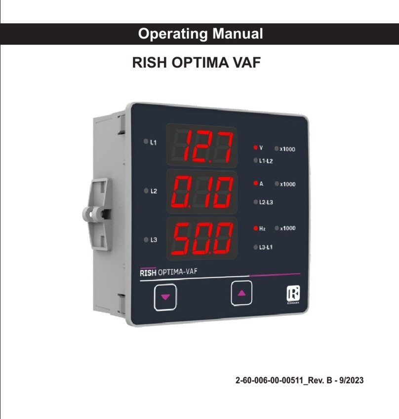
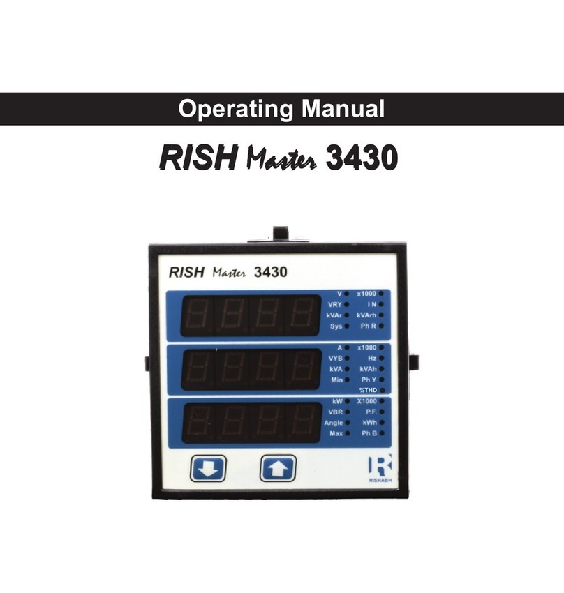
Rish DPM User manual

DMAN-00IM-0764 Rev_B 09/2019
OPERATING MANUAL
PROGRAMMABLE DPM

INDEX
PROGRAMMABLE DPM
AC Ammeter (3 )Φ
Installation & Operating Instructions
Section Contents
1. Introduction
2. Measurement Reading Screens
3.
4. Installation
4.1 EMC Installation Requirements
4.2 Case Dimensions and Panel Cut-out
4.3 Wiring
Programming
3.1 Set Up Screens
3.1.2 Auto Scrolling
3.1.1 Current Transformer Primary value
4.4 Auxiliary Supply
4.5 Fusing
4.6 Earth / Ground Connections
5. Connection Diagrams
Specifications
6.
1

1. Introduction
The Instrument is a panel mounted 48 x 96mm Digital Panel Meter for the measurement
of AC current in three Phase. The Instrument accepts input from 3PH nano CT.
The instrument integrates accurate measurement technology.
display with 14mm digit height. Programmable DPM can be
configured and Programmed at site for the following :
CT Primary and Auto Scrolling.
through the available parameters the two keys has function as follows:
1. : Scrolls through parameter in upward sequence. Display sequence L1 current,
2. : Scrolls the parameters in Reverse of above sequence.
V
L2 current, L3 current, System Current and back to L1.
X1000
L1
L2
L3 V
L1
L2
L3 A
RMS
TRUE
TABLE 1: Parameters Displayed
Ampere
Ampere
Ampere
Ampere
L1 Current
L2 Current
L3 Current
System Current
Measured Parameters Unit of measurement
The Parameters are displayed with Ultra high brightness LED
The front panel has two push buttons for user interface to scroll
2

2 . Measurement Reading Screen
In normal operation the user is presented with the measurement reading screens. These
screens may be scrolled through one at a time in incremental order by pressing the key
and in decrementing order by pressing key.
3. Programming
The following sections comprise step by step procedures for configuring the Instrument.
To access the set-up screens press and hold the “ ” and “ ” Keys Simultaneously.
This will take the User into the Current Transformer Primary value selection Screen Followed
3.1 Set Up Screens
by “CtPr” on Display (Sec 3.1).
3.1.1 Current Transformer Primary Value
This screen displays “CtPr” message followed by previously set CT primary value on display.
This screen enables user to set CT primary as 63 or 125 or 250 A.
Pressing the “ ” key accepts the present value and
advances to the “Auto Scrolling or Fixed Screen Selection”
menu.
Pressing the “ ” key scrolls through values 63, 125 and 250.
X1000
L1
L2
L3 V
L1
L2
L3 A
RMS
TRUE
3

Current Transformer Primary Value Confirmation
This screen will only appear following an edit of the Current
Transformer Primary Value.
If the set value is to be corrected, pressing the “ ” key will
return to the “Current Transformer Primary Value Edit” stage.
Pressing the “ ” key sets the value and then advance to the
“Auto Scrolling or Fixed screen” .
X1000
L1
L2
L3 V
L1
L2
L3 A
RMS
TRUE
3.1.2 Selection of Auto Scrolling or fixed Screen
Pressing the “ ” key will scroll between “Yes” and “No”.
Select “Yes” for Auto scrolling of parameter display and Select
“No” for fixed display screen.
Pressing the “ ” key will accept the display value and exit from
set up and enter into measurement mode.
X1000
L1
L2
L3 V
L1
L2
L3 A
RMS
TRUE
Pressing the “ ” key set the selected option and Exit set up
with entering into measurement mode.
Auto / Fixed Screen Confirmation
Pressing the “ ” key re-enter Screen selection menu.
X1000
L1
L2
L3 V
X1000
L1
L2
L3 A
RMS
TRUE
4

4. Installation
Mounting of Instrument is featured with easy mounting. Push the meter in panel slot, it will click fit
into panel with the four integral retention clips on two sides of meter. If required additional support is
provided with swivel screws (optional) as shown in figure.
As the front of the enclosure conforms to IP 50.
additional protection to the panel may be obtained
by the use of an optional panel gasket. The terminals
The Instrument should be mounted in a reasonably
stable ambient temperature and where the operating
0
temperature is within the range 0 to 50 C . Vibration
should be kept to a minimum and the product should
at the rear of the product should be protected from
not be mounted where it will be subjected to
excessive direct sunlight.
Caution
1. In the interest of safety and functionality this product must be installed by a qualified
engineer, abiding by any local regulations.
2. Voltages dangerous to human life are present at some of the terminal connections of
this unit. Ensure that all supplies are de-energised before attempting any connection
disconnection.
3. These products do not have internal fuses therefore external fuses must be used to
ensure safety under fault conditions.
liquids.
Swivel Screw
5

4.1 EMC Installation Requirements
This product has been designed to meet the certification of the EU directives when installed
to a good code of practice for EMC in industrial environments, e.g.
1. Screened output and low signal input leads or have provision for fitting RF suppression
components, such as ferrite absorbers, line filters etc., in the event that RF fields cause
problems.
Note: It is good practice to install sensitive electronic instruments that are performing critical
functions, in EMC enclosures that protect against electrical interference which could cause a
disturbance in function.
2. Avoid routing leads alongside cables and products that are, or could be, a source of
interference.
3.
4.
To protect the product against permanent damage, surge transients must be limited to
2kV pk. It is good EMC practice to suppress differential surges to 2kV at the source.
The unit has been designed to automatically recover in the event of a high level of
transients. In extreme circumstances it may be necessary to temporarily disconnect the
auxiliary supply for a period of greater than 5 seconds to restore correct operation.
ESD precautions must be taken at all times when handling this product.
4.2 Case Dimensions and Panel Cut Out
Mounting Position Installation Cutout
6

4.2.1 Case Dimensions of Current Transformer
X308: 63A / 100mA CT X306: 125A / 100mA CT
X307: 250A / 100mA CT
7

4.3 Wiring
Input connections are made directly to connector type for 48 x 96mm DPM.
Numbering is clearly marked on the connector. Choice of cable should meet local regulations.
4.4 Auxiliary Supply
EINE should ideally be powered from a dedicated supply, however it may be powered
from the signal source, provided the source remains within the limits of the chosen auxiliary
voltage.
4.5 Fusing
It is recommended that all voltage lines are fitted with 1 amp HRC fuse.
4.6 Earth/Ground Connections
For safety reasons, panels and accesoriess should be grounded in accordance
Note : 1) It is recommended to use wire with lug for connection with meter.
2) For disconnecting the device a switch or circuit-breaker shall be included at the
site and shall be within easy reach of the operator. The specification are as below.
For aux. = At least 1.5 times of applied Power supply.
5. Connection Diagrams
L1
L2
13
L
O
A
D
67910
L3
N
LN
AUX SUPPLY
BA
+ -
Connect External Current Transformer Secondary as shown below.
1 - COM
3 - 1S1
6 - COM
7 - 2S1
9 - COM
10 - 3S1
Note:- All COM Terminals of Meter
are internally shorted.
No need to short externally.
8

6. Specifications :
Auxiliary Supply :
AC-DC Auxiliary Supply 40V to 300V AC/DC (+/- 5%)
20V to 60V DC / 20V to 40V AC
Overload Indication :
“-oL-”
(If input is greater than 125% of secondary value)
Input current:
Nominal Input Current Ranges 100 mA ( External 3PH Nano CT Input)
Max continuous input current 120% of rated value
System CT Primary values 63 or 125 or 250 A Programmable onsite
Nominal input current burden <0.1VA approx. per phase
For continuous
input current 120%
Frequency Range for AC Aux. Supply 45 to 65 Hz
VA Burden < 4 VA at 240V, 50Hz
< 1 VA at 24V AC/DC
Reference conditions for Accuracy :
Reference temperature
Input waveform
Auxiliary supply voltage
Auxiliary supply frequency
0 0
23 C + 2 C
Sinusoidal (distortion factor 0.005)
Rated Value + 1 %
Rated Value + 1 %
Operating Measuring Ranges
Frequency 45 ... 65 Hz
Current Range 5 ... 120 % of Rated Value
Input Frequency 50 Hz / 60 Hz
Current Range 10...100% of Nominal Value
Overload Withstand :
Current 4 X Rated Value for 1 Second, repeated
5 times at 5 min interval.
9

Display
1 line 4 digits .
LED
Temperature Coefficient 0
(For Rated value range of use 0... 50 C )
For Displaying Units and Parameter
Annunciator LEDs
2 Keys
Controls
User Interface
0
0.05% / C
Current
Digit height
14mm
Applicable Standards
IEC 61326-1:2005
IEC 61010-1: 2001,Permantly Connected use
EMC
Safety
IEC 60529
IP for water & dust
Safety
2
III
Pollution Degree
Installation Category
High Voltage Test 2.2 kV AC, 50 Hz for 1 minute
10V/m min-Level 3 industrial low level
Electromagnetic radiation environment
Environmental conditions
0
0 to 50 C
0
-25 to 70 C
0 .. 90 % (Non condensing)
Minimum 3 minute
15g in 3 planes
10 .. 55 Hz, 0.15mm amplitude
Operating temperature
Storage temperature
Relative humidity
Warm up time
Shock
Vibration
Accuracy
Current 0.5% of Nominal value.
10

Enclosure
IP50
Front
IP20Back
Dimension and weight:
Bezel Size (DIN 43718)
Overall Depth
Weight
Panel Cut-Out
Polycarbonate Housing ,
Material
Screw-type terminals
Terminals
The Information contained in these installation instructions is for use only by installers trained
It is the user's responsibility to determine the suitability of the installation method in the
user's field conditions. Manufacturer only obligations are those in Manufacturer standard
Conditions of Sale for this product and in no case will Manufacturer be liable for any other
to make electrical power installations and is intended to describe the correct method of
installation for this product. However, Manufacturer has no control over the field condition
which influence product installation.
Incidental, indirect or consequential damages arising from the use or misuse of the products.
81.5 mm
250g Approx.
48mm X 96mm
43.5 + 0.6mm X 92 + 0.8mm
11

WARRANTY
Dear Customer,
You are now the privileged owner of DPM, a product that ranks the first of its kind in the world.
Company provides 12 months warranty from the original date of Purchase against defective
material and workmanship.
In the unlikely event of failure of the instrument / accessories within the warranty period.
Company will repair meter / accessories free of charge. Please hand over the meter /
accessories to the dealer / stockist from whom you have purchased along with this card and
relevant Cash Memo / Invoice. This warranty entitles you to bring the meter / accessories at
your cost to the nearest stockist / dealer and collect it after repairs.
NO TRANSPORTATION CHARGES WILL BE REIMBURSED.
The warranty is not valid in following cases:
1. Warranty card duly signed and stamped and original Cash Memo / Invoice is not sent
along with DPM.
2. Complete warranty card is not presented to authorised person at the time of repairs.
3. Meter / accessories is not used as per the instructions in the instruction manual.
4. Defect caused by misuse, negligence, accidents, tampering and Acts of God.
5. Improper repairing by any person not authorised by the company.
6. Any sort of Modification, Alteration of any sort is made in electrical circuitry.
7. Seal provided inside/outside is broken.
In case of dispute to the validity of the warranty, the decision of Company service center will
be final.
If you bought this DPM directly from the company, and if you notice transit damage, then you
must obtain the insurance surveyors report and forward it to Company .
Thank you.
(To be filled by authorized dealer)
Model No.: Serial No. :
Date of Purchase : Cash Memo / Invoice No. :
Dealer’s Signature : Dealer’s Stamp :
12
Table of contents
Other Rish Measuring Instrument manuals