phase II+ SRG-4500 User manual

Portable Surface Roughness Gauge
Part No. SRG-4500
Operation Manual
21 Industrial Ave Upper Saddle River, NJ. 07458
Tel: (201)962-7373 Fax: (201)962-8353
E-Mail: [email protected]
Web Site: http://www.phase2plus.com

CONTENT
1SRG-4500 OVERVIEW....................................................................................................
1.1 OUTLINE OF THE SRG-4500.........................................................................................................4
1.2 MEASUREMENT PRINCIPLE ..........................................................................................................4
1.3 FEATURES OF SRG-4500..............................................................................................................4
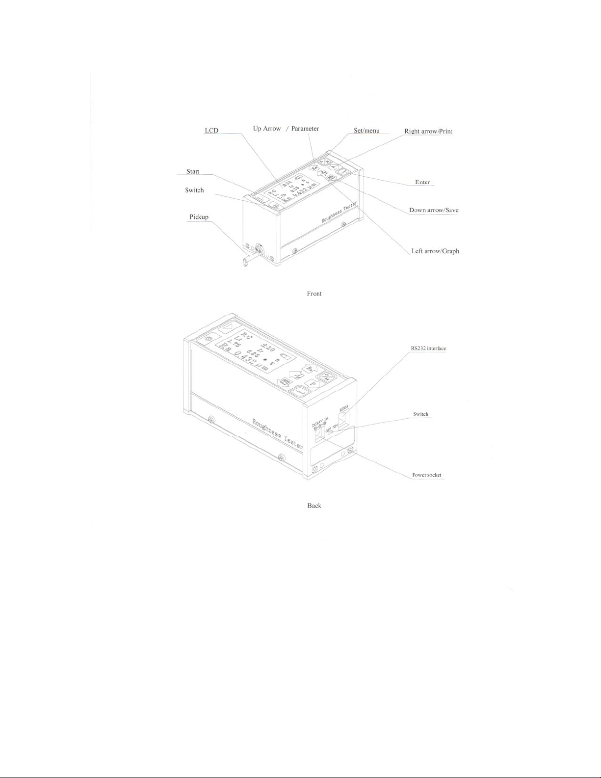
1.4 NOMENCLATURE..........................................................................................................................4
1.5 FUNCTION OF SHEET KEYS..........................................................................................................6
1.6 STANDARD CONFIGURATION .......................................................................................................7
1.7 BASIC CONNECTION ....................................................................................................................7
1.8 TURNING ON/OFF THE POWER SUPPLY .......................................................................................7
1.8.1 Turning On/Off Power button ................................................................................................7
1.8.2 Turning On/Off Battery switch..............................................Error! Bookmark not defined.
1.9 BATTERY CHARGING....................................................................................................................8
2SETTINGS SYSTEM INFORMATION..........................................................................................
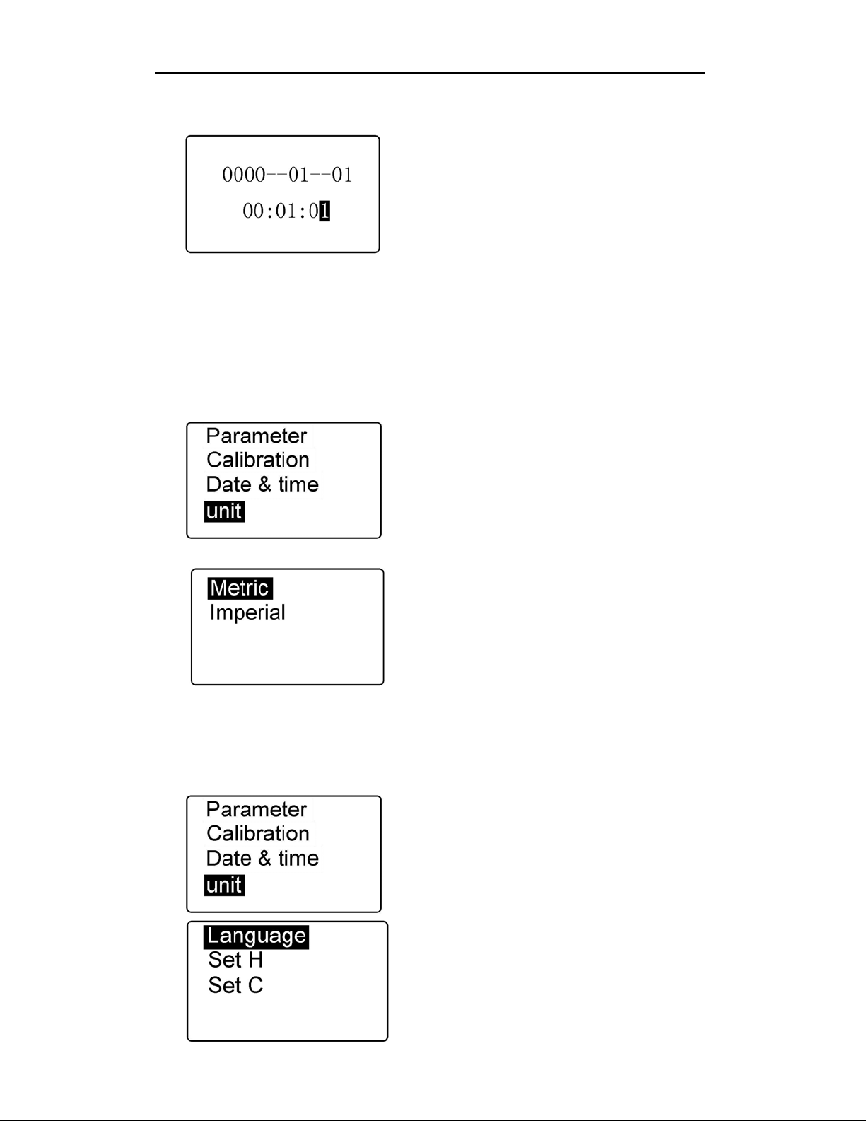
2.1 SETTING THE CLOCK .......................................................... ERROR!BOOKMARK NOT DEFINED.
2.2 UNIT OF MEASUREMENT ..............................................................................................................9
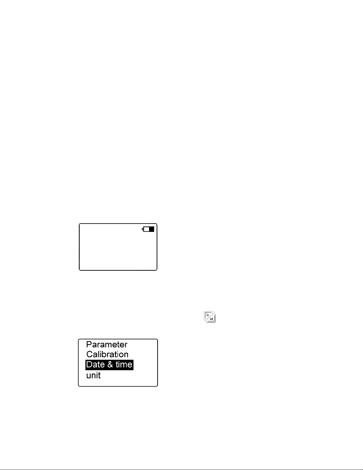
2.3 SETTING LANGUAGE....................................................................................................................9
3MEASUREMENT OPERATION.................................................................................................
3.1 STYLUS POSITION.......................................................................................................................10
3.2 CALIBRATION.............................................................................................................................10
3.3 STARTING MEASUREMENT .........................................................................................................11
3.4 RESULTS DISPLAY ......................................................................................................................12
3.5 SAV E /READ MEASUREMENT RESULTS ......................................................................................13
3.6 PRINT MEASUREMENT RESULTS .................................................................................................14
3.7 DISPLAY MEASUREMENT RESULTS IN THE COMPUTER ...............................................................15
4SET MEASUREMENT CONDITIONS............................................................................................
4.1 MODIFY SAMPLING LENGTH ......................................................................................................15
4.2 MODIFY ASSESSMENT LENGTH.................................................................................................15
4.3 MODIFY FILTER ..........................................................................................................................15
4.4 MODIFY RANGE .........................................................................................................................16
4.5 MODIFY THE PARAMETERS OF MAIN INTERFACE.......................................................................16
4.6 MODIFY THE UNIT OF MEASUREMENT .......................................................................................16
4.7 SELECT PRINT PARAMETERS ......................................................................................................16
4.8 SETTING HVA L U E ......................................................................................................................16
4.9 SETTING CVA L U E ......................................................................................................................17
5MAINTENANCE ...........................................................................................................
5.1 PICKUP ........................................................................... ERROR!BOOKMARK NOT DEFINED.17
5.2 SRG-4500 ...................................................................... ERROR!BOOKMARK NOT DEFINED.17

5.3 BATTERY ....................................................................................................................................18
5.4 CALIBRATION SPECIMEN............................................................................................................18
6TROUBLESHOOTING .......................................................................................................
7OPTIONS ...............................................................................................................
8TECHNICAL PARAMETERS..................................................................................................
9REFERENCES.........................................................................................................
9.1 TERMS........................................................................................................................................21
9.1.1 Terms.....................................................................................................................................21
9.1.2 Traversing Length.................................................................................................................21
9.2 PARAMETERS DEFINITIONS........................................................................................................22
9.2.1 Arithmetical Mean Deviation of Profile Ra.........................................................................22
9.2.2 Root-mean-square Deviation of Profile Rq..........................................................................22
9.2.3 Maximum Height of Profile Rz.............................................................................................23
9.2.4 Total Peak-to-valley Height Rt.............................................................................................23
9.2.5 Maximum height of Profile Peak Rp....................................................................................23
9.2.6 Maximum Depth of Profile Valley Rv...................................................................................23
9.2.7 Mean Spacing of Local Peaks of Profile RS........................................................................24
9.2.8 Mean Spacing of Profile elements RSm...............................................................................24
9.2.9 Ten Point Height of Irregularities RzJIS..............................................................................25
9.2.10 Maximum Height of Profile RyJIS ...................................................................................25
9.2.11 Skewness of the profile RSk..............................................................................................25
9.2.12 Third Maximum Peak-to-valley Height R3z ....................................................................25
9.2.13 Rmax.................................................................................................................................26
9.2.14 Peak count Rpc.................................................................................................................26
9.2.15 Material ratio curve of profile Rmr .................................................................................26
9.2.16 Material length ratio Rmr
(
c
)
......................................................................................26
9.3 RECOMMENDED TABLE OF THE SAMPLING LENGTH...................................................................27

SRG-4500 OVERVIEW
Outline of the SRG-4500
The SRG-4500 is a portable, lithium-ion battery powered instrument used for checking
surface finish with the measured values displayed on a digital readout. This instrument can be
utilized in a laboratory setting, a shop inspection area, or wherever on-site surface roughness
testing is required.
Note:
Although this instrument is designed and built to withstand the rigors of handling and usage,
it is a sensitive precision instrument and should be treated with care to assure measurement
accuracy and reliable performance.
Measurement principle
Skid type surface roughness testers are common instruments used on the shop
floor. A diamond stylus is traversed across the specimen and a piezoelectric
pickup records all vertical movement. Peaks and valleys are recorded and
converted into a known value of a given parameter.
Features of SRG-4500
15 parameters: Ra, Rq, Rz, Rt, Rp, Rv, RS, RSm, Rz(JIS),
Ry(JIS) ,RSk, R3z, Rmax, RPc, Rmr
High accuracy inductance pickup;
Four filtering methods of RC, PC-RC, GAUSS and D-P;
Compatible with four standards of ISO, DIN, ANSI and JIS;
Can store 15 sets of measurements results
128×64 dot matrix LCD displays all parameters and graphs;
Data processing with high speed and low power consumption;
Built-in high capacity lithium ion chargeable battery. Consecutive work time is longer than 20 hours;
Can be connected to your PC printer to print all parameters and graphs;
Built-in standard RS232 interface enables communication with PC;
Automatic switch off, memory and various prompt instructions;
Optional printer, analysis software and measurement platform.

Right arrow/Print
Set/men
u
Enter
Down arrow/Save
Left arrow/Graph
Up Arrow /Parameter
LCD
Start
Switch
Pickup

Parameter
value
Parameters measurement unit
Sample length
Number of sample length
Sample length
Assess length value
Assess length
0.
Ra
1.75
ln
RC
μ
008 m
50.25 *
lr
¡À20
n
Filter Range Battery
LCD
Function of Keypad
Press start measuring key. start a Measuring.
Power button. When day-to-day use, it does not turn off the battery to retain stored
information. If long-term non-use of equipment, please turn off the battery switches of
the rear side of the Instrument.
Up arrow / Parameters key. In the main interface, press the button to enter the
parameter display, press the Enter-key exit.
Down arrow / storage key. In the main interface, press the Store button to enter the storage
interface.
Left arrow / graphic key. In the main interface, press the button to enter the graphical display
interface.
The right arrow / Print button. In the main interface, press the button to start the printer to print
all the measurements results.
Set / Menu button. In the main interface, press the button to enter the measurement conditions
set status. Long by about 3 seconds of the keys to enter the main menu interface.
Enter key. Interface at all, used to identify modify settings results or exit of the interface.

Standard Configuration
Name Qty
SRG-4500 main unit 1
Standard pickup(stylus) 1
Roughness specimen 1
AC adapter 1
Basic Connection
main unit
Pickup
pickups and connection
Turning On/Off the Power Supply
TurningOn/OffBatteryswitch
The battery switch is on the right rear side of the instrument. When powering off for the
night, this switch should be placed to the OFF position to cut off power supply. The SRG-4500
will automatically power on when the switch is moved to the ON position.

TurningOn/OffPowerbutton
Power button is located in the lower-left corner of keypad. Use this power button during
normal usage. If the unit will be off for an extended period of time, the battery switch (mentioned
above) should be switched to the OFF position. All data will be saved using either battery switch
or keypad button.
Battery Charging
There is a battery symbol in the top right corner of the SRG-4500. When all of the black bars
inside the symbol disappear, the battery is low and the unit must be charged up
Please note that the charger has a built-in light. This light will be RED when the unit is charging
and will turn GREEN when the unit is fully charged.
Typically, a charging time is approximately 3 hours .
Settings System Information
1) The main interface
The Home screen of the SRG-4500 is as shown
to the left. This is the screen that will be on display
upon power up. The home screen shows all
measuring parameters that have been previously set.
Parameters such as sample length, assessment of the
length, range, filter and measurement units will be
shown.
In the main interface, each button on the keypad will implement a specific function.
2)Main menu
To enter the main menu, press and hold the
Set / Menu button
Use up or down arrows to scroll thru selections shown
on the display.
1.75
Ra
RC
ln
50.25 *
008
0. μ
m
¡À20
lrn

Measurement operation
3)Setting the Clock
Press and Hold the Set/Menu button to
enter the main menu. Press the Down arrow
button to scroll down to Date and Time. Press
the Enter (Back arrow) button to enter this
parameter. Press the Up or Down arrow buttons
to maneuver the cursor to the numeral that needs
to be changed and then press the Left or Right Arrow buttons to change that number. When
complete, press the Set/Menu button to return to the main menu screen. If you have
completed all of your selections, you should press the Set/Menu button again to return to the
main measurement screen.
Unit of measurement: Inch/Metric
1Main menu
While in the main menu, scroll down to UNIT.
Press the Enter(back arrow) button. The display will
show Metric or Imperial. Metric will be highlighted.
Use the Up or Down Arrow buttons to select the unit
and then press the Enter (back arrow) button to
accept. Then press the Set/Menu button to save and
return back to the main measuring screen.
Setting Language
1) Main menu
2) While in the main menu, scroll down to Language..
Press the Enter(back arrow) button. The display will
show Language, Set H and
Set C. Language will be highlighted. Use the Up or
Down Arrow buttons to select the unit and then press
the Enter (back arrow) button to accept. Then press the
Set/Menu button to save and return back to the main
measuring screen.
Please see section 4.7 and 4.8 for further
information!

Measurement operation
Stylus position
Prior to taking a test, whether on your part or using
the calibration reference standard, the stylus
position must be leveled on the application. The
SRG-4500 has a built-in zero indicator to make this
simple and accurate.
Position the unit on the supplied reference standard
or your work piece and press the Enter (back arrow) button. The leveling indicator will appear on
the display. Using the supplied height adjusters on each side of the unit, raise or lower these slides
until the arrow falls on or close to the “0” in the center of the leveling scale. Once achieved, press
the Enter(back arrow) button to return to the main measuring screen.
Calibration
: using supplied reference standard
Accuracy of the SRG-4500 is +/-10% of actual value
Prior to measurement on your parts, you should verify the accuracy of the unit by performing a
quick calibration using the supplied reference standard.
If the difference between the measured value and the specimen value is greater than the
scope of equipment requirements, or user requirements are more accurate, you can use that value
of the calibration function to correct measurement results.
The calibration steps are as follows: (Must be Calibrated in METRIC mode only)
1) Calibration
Press and Hold the Set/Menu button to bring up the
main menu. Use the up or down arrow buttons to scroll
down to Calibration. Press the Enter (back arrow) button to
enter this parameter.
.
2) Setting correct values
Press the down arow button to choose the closest
roughness value of your part. In other words, if the
roughness of your part is approx. 5µm, you should set
the calibration on the+/-20µm setting. If your part is
approx. 47 µm, you should set calibration under +/-40
µm, etc.
Pickup Position
-
+
0

Measurement operation
Starting measurement
1) Starting measurement
Once all parameters have been set, you should
place the SRG-4500 on work piece. In the main
measuring screen, press start button on the top left
corner of the keypad to start measuring .
Do not move unit once test has begun!
2) Starting measurement
As the stylus moves across the work piece, the
measuring indicator will show the progress.
3) Digital filter
Sampling ends. Beginning digital filter.
4) Calculating parameters
Filtering ends, Calculating parameters
1.75
Ra
RC
ln
50.25 *
008
0. μ
m
¡À20
lrn
Press〔M〕to stop
Measuring
Data filter
Data calculate

Measurement operation
Results display
Once the value has been obtained, you can go through the following methods to the observe the
results in 15 different scales as well as profile and ratio curves.
1) Roughness Scales
After your test has been completed, press the UP
arrow button to show all the value in all of the
different scales. Press the DOWN arrow button to
scroll through the pages. Press the Setting/Menu
button to return to the main measurement screen.
2) Profile
To viw your results in profile, press the LEFT
arrow button after test has been taken.
While on this page press the Enter(back arrow)
Button to zoom in on the profile.
To view results in the ratio curve, press the UP
or Down Arrow button. To exit, press the Set/Menu
button.
Rt
Rp
Rv
Ra
Rq
Rz 0.035
0.120
0.064
0.027
0.031
0.008
μm
μm
μm
μm
μm
μm
0.008
Ry μmJIS
=
=
=
=
=
=
=
RSm
RS 0.2083
0.0089 m m
m m
0.072
R3z μm
Rmax
RPc 1.207
5/CM
μm
RSk 1.207
0.072
Rz μmJIS
=
=
=
=
=
=
=
0.0000
Rmr3
Rmr1
Rmr2
Rmr4
=
=
=
=0.0000
0.0000
0.0000
Vv:5× lr:1
(%Rt)
100
0
c
100
(%)
Rmr

Measurement operation
Save / Read measurement results
SRG-4500 can save 15 sets of measurement results.
1)Save the current data
After taking a test, press the DOWN arrow button.
The display shown to the left will come up. Press the
Enter (back arrow) button to save the current reading.
Press the Enter (back arrow) button again and the unit
will automatically store the value. Press the Set/Menu
button to exit back to main measurement screen.
Press the Enter key to confirm and save the current
data.
Save progress bar.
2)Read historical data
To view saved data, press down arrow to enter
the save / read interface. Press up (down) arrow to
select the READ DATA, press the Enter key to view
results.
Press the UP or Down arrow buttons to scroll
through the 15 groups of saved data. Press the Enter
(back arrow) button to view data in that group.
Read the progress bar.
00:01:01
Save No. 01
00-01-01
Save No. 01
Read No. 01
00:01:01
00-01-01
Read No. 01

Measurement operation
Print measurement results
1)Start printing
To print data to external mini printer, press the Right
arrow button while in the main measurement screen. The
SRG-4500 will print results in all parameters and profile.
2)Printing paper
Printing...
SRG-4500 Surface Roughness
Teste
r
Date 2008-01-01
Time 13:08:09
l
r
0.8
mm
ln
4
mm
Filte
r
Gauss
Ra μ
m
R
q
μ
m
R
t
μ
m
Rz μ
m
RSm
mm
RS mm
Rv μ
m
Rp μ
m
Rz(JIS) μm
Ry(JIS) μ
m
RSk
R
3
z
μ
m
Rmax
μ
m
RPc /
cm
Rmr(c
1= μm) %
Rmr(c
2= μm) %
Rmr(c
3= μm) %
Rmr(c
4= μm) %
Vv ×5000
Vh ×500
Ver. 2.0
μ
m/10mm
Hor. 20.0
μ
m/10mm
C

Measurement operation
Display measurement results in the computer
Optional software for the SRG-4500 will allow database management, graphical display,
parameter display, measurement operation, print management, document management functions.
4)Set measurement parameters
While in the main measurement screen, press Set / Menu button to parameter settings section.
¡À20
0.25 *1.75
Ra
ln
RC
lr
5
m
μ
n
Measurement conditions set interface
4.1) Modify sampling length
Press the UP or Down arrow buttons to select
the parameter to be modified(sampling Length).
Press the Left or Right arrow button to modify the
selection. The selected area will show the cycle of
0.25,0.8 and 2.5. once selection has been made,
press either the Left or Right Arrow button to go to
the next parameter.
4.2) Modify Traverse length
Press the UP or Down arrow buttons to select
the parameter to be modified(Traverse Length). Press
the Left or Right arrow button to modify the selection.
Press the left (right), arrows to show the cycle in
order 1,2,3,4,5.
4.3) Modify filter
Press the UP or Down arrow buttons to select the
parameter to be modified(Filter). Press the Left or Right
arrow button to cycle through the different filters.
RC, PC-RC, GAUSS, D-P.

Measurement operation
4.4) Modify range
Press the UP or Down arrow buttons to select
the parameter to be modified(Range). Press the Left
or Right arrow button to scroll through the ranges.
20, 40, 80,
4.5) Modify the Roughness Scale
Press the UP or Down arrow buttons to select the
parameter to be modified(Roughness Scale). Press the
Left or Right arrow button to scroll through the list of
scales.
4.6) Modify the unit of measurement(Inch/Metric)
Press the UP or Down arrow buttons to select the
parameter to be modified(Inch/Metric unit). Press the
Left or Right arrow button to choose unit.
4.7) Setting H value
When user require RPc peak count parameter, the SRG-4500 must be set to H Value
while in the main measurement screen, press
and Hold the Set/Menu button to enter the menu.
{Press the Down arrow button to scroll down to Set
H. Press the Enter (back arrow) button to select H
value.

Measurement operation
To make adjustments, press the Up or Down
arrow button to move cursor to correct position. Press
the Right or Left arrow button to change the value.
Press the Enter(back arrow) button to save and return
to menu.
4.8) Setting C value
When measuring profile material ratio Rmr parameter , need to set C value.
To make adjustments, press the Up or Down
arrow button to move cursor to correct position. Press
the Right or Left arrow button to change the value.
Press the Enter(back arrow) button to save and return
to menu.
Press the Enter button to shift and then press either the
Up or Down arrow buttons to select group.
Press the Enter (back arrow) button to exit.

Maintenance
Maintenance
Stylus:
1) After completion of measuring work, please remove stylus from unit and return to case.
2) The stylus is extremely sensitive. Please don’t touch the tip or run it across a surface that
hasn’t been cleaned. These are also sensitive to high humidity. Please store in dry cool place.
Main Unit:
1)Always keep clean using a soft cloth. Do not use harsh cleaners on this as it will diminish the
finish.
2)The SRG-4500 is a precise sensitive instrument and should be handled accordingly.
Battery:
1)Battery power is shown on the top right side of the display when in main measurement screen.
When the battery symbol is empty, its time to recharge the unit.
2)Approx. charging time is 3 hours.
Calibration Reference Standard:
1) Always keep this clean. Store in carry case when not in use.
2) Avoid scratches to the work area surface of the standard

Troubleshooting/Options
Troubleshooting
Optional Accessories: SRG-4500
1) Precision Support Stand
2) Stylus Extension
3) Special stylus for round and grooved surfaces
Error messages Possible reasons Troubleshooting
Out of range! Maximum value of measured
signal exceeds measuring range;
1.Press Esc key to return;
2.Enter menu setting status,
increase measuring range,
press Esc key to return;
3.Measure again.
No data! Wrong operation results in failed
measuring;
1.Press Esc key to return;
2.Check if preparation for
measuring is correct;
3.Switch on and measure again.
A/D failure Hardware circuit fault; 1: Switch off and switch on
again;
2: Press Reset key;
3: Return to Phase II for repair.
Motor failure Mechanical fault; 1: Switch off and switch on
again;
2: Press Reset key;
3: Return to Phase II for repair.
Pickup failure
Pickup is in automatic return
process
Press Esc key to return and wait
till pickup returns to the start
position

Technical parameters
N
ame Content
Measuring
range Z Axis(Vertical) 160μm
X Axis(Horizontal) 17.5mm
Resolution Z Axis(Vertical) 0.01μm/±20μm
0.02μm/±40μm
Measurement
item Parameters Ra, Rq, Rz, Rt, Rp, Rv, RS, RSm,Rz(JIS) Ry(JIS)
RSk、R3z、Rmax、Rpc、Rmr;
Standard ISO, ANSI, DIN, JIS
Graphic Roughness profile, Material ratio curve, Direct profile
Filter RC,PC-RC, Gauss, D-P
Sampling length (lr) 0.25,0.8,2.5mm
Assessment length (ln) Ln= lr×n n=1~5
Pickup principle Differential inductance
Stylus Natural Diamond, 90cone angle, 5μm tip radius
Force <4mN
Skid Ruby, Longitudinal radius 40mm
Traversing speed lr=0.25, Vt=0.135mm/s
lr=0.8, Vt=0. 5mm/s
lr=2. 5, Vt=1mm/s
Return Vt=1mm/s
Accuracy Less than or equal to ±10%
Repeatability Less than or equal to 6%
Power supply Built-in Lithium ion battery, AC adapter 8.4V,800mA
L×
W
×H 119×47×65mm
Weight Approx. 380g
Table of contents
Other phase II+ Measuring Instrument manuals