7
2. INSTALLATION
Models are available in Type 1 indoor or Type 3R rain proof enclosures. The unit
should be securely mounted to a level surface and care taken to minimize the
introduction of dust and other contaminants into ventilation openings.
2.1 PHYSICAL INSTALLATION
Properly locating Phase Perfectis important to the performance and normal
operating life of the unit. The unit should be installed in a location free from:
Excessive dirt and dust
Corrosive gases or liquids
Excessive vibration
Airborne metallic particles
It is important that the unit be located away from excessive dirt and dust. Phase
Perfectshould be set on a clean, flat horizontal surface. Elevating the unit
above the ground will help to reduce the introduction of dust and contaminants
into the enclosure.
Models DPC-20 and DPC-30 are provided with lifting brackets inside the
enclosure. CABLES, STRAPS OR CHAINS USED FOR LIFTING THESE UNITS
MUST BE ATTACHED ONLY TO THE PROVIDED BRACKETS. Access the
brackets by removing the top cover of the enclosure. Brackets with a hole for
attaching lifting equipment are located on each side-wall of the enclosure.
In order to provide proper ventilation, do not obstruct the open space under and
around the enclosure. Make sure air intake and exhaust openings are not
obstructed. If the unit is mounted in a cabinet or shed, make certain there is
adequate ventilation to provide cooling for the unit.
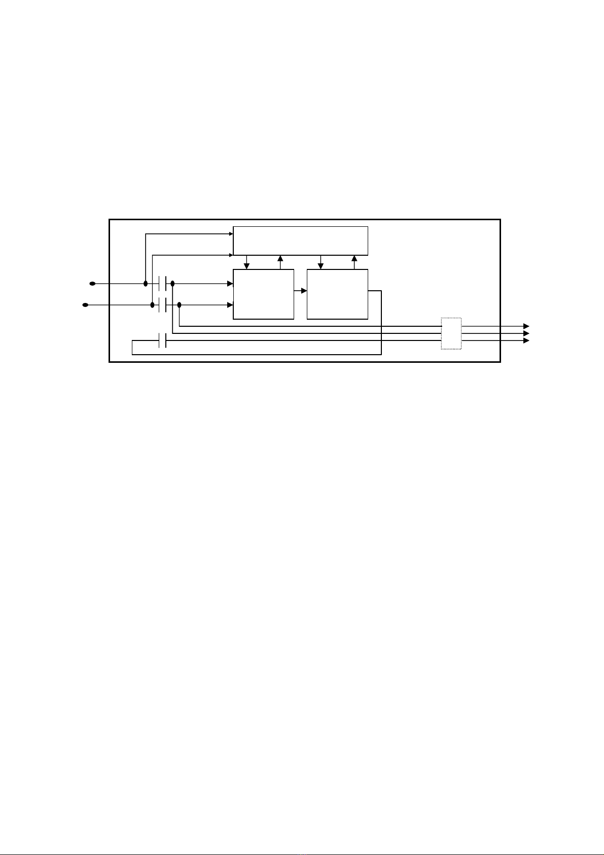
2.2 ELECTRICAL INSTALLATION
Electrical connections to the Phase Perfectare made behind the front panel of
the enclosure, as described in section 2.2.1. Phase Perfectis available
configured for use as a motor starter with single motor loads, or configured as a
power supply for multiple loads. These configurations are described in section
2.2.2.
Status lights provide information about the status of the Phase Perfectunit, and
about the entire system into which the unit is wired. The status lights are very
useful in troubleshooting system problems. Detailed information on the use of
the status lights for troubleshooting purposes is found in section 5.2.
A panel with terminal blocks for connecting wires is found behind the front panel.
Section 2.2.1 below illustrates the wiring connections and controls found on the
panel. Section 2.2.1.1 provides a description of general wiring considerations.
Section 2.2.1.2 provides diagrams of typical input power wiring configurations,
and discusses important considerations involved in input wiring from various
sources.