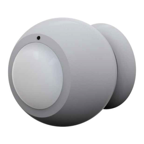
Philio Technology Corporation PSM01 User manual

Image not readable or empty
images/manufacturers/Philio.png
PHI_PSM01
Z-Wave 3 in 1
Sensor(Door-
/Window,
Temperature,
Illumination)
Firmware Version : 1.0
Quick Start
SThis device is a Z-Wave Sensor. Tripple Click the Temper Switch on the backside to confirm inclusion,
exclusion and association.
Please refer to the chapters below for detailed information about all aspects of the products usage.
What is Z-Wave?
This device is equipped with wireless communication complying to the Z-Wave standard. Z-Wave is the
international standard for wireless communication in smart homes and buildings. It is using the
frequency of 868.42 MHz to realize a very stable and secure communication. Each message is reconfirmed
(two-way communication) and every mains powered node can act as a repeater for other nodes (meshed
network) in case the receiver is not in direct wireless range of the transmitter.
Z-Wave differentiates between Controllers and Slaves. Slaves are either sensors (S) transmitting metered or
measured data or actuators (A) capable to execute an action. Controllers are either static mains powered
controllers (C) also referred to as gateways or mobile battery operated remote controls (R). This results in a
number of possible communication patterns within a Z-Wave network that are partly or completely supported
by a specific device.
1. Controllers control actuators
2. Actuators report change of status back to controller
(c) 2012 Z-Wave Europe GmbH, Goldbachstr. 13, 09337 Hohenstein-Ernstthal, Germany, All rights reserved, www.zwaveeurope.com - pp 1

3. Sensors report change of status of measured values to controller
4. Sensors directly control actuators
5. Actuators control other actuators
6. Remote controls send signals to static controllers to trigger scenes or other actions
7. Remote controls control other actuators.
There are two different role a controller can have. There is always one single primary controller that is managing the
network and including/excluding devices. The controller may have other functions - like control buttons - as well. All other
controllers don't manage the network itself but can control other devices. They are called secondary controllers. The
image also shows that its not possible to operate a sensor just from a remote control. Sensors only communicate with
static controllers.
Product description
The Z-Wave 3 in 1 sensor is designed with three detection sensors:
Door-/Window
Temperature
Illumination
The sensor consists of two parts; a Detector and a Magnet. They are designed to be fitted to doors or
windows with the Magnet mounted on the opening part and the Detector mounted on the fixed frame.
Opening the protected door/window will remove the magnetic field, trigger the detector and generate an
alarm condition, (if the system is armed). The sensor can also applied to automatic light control, one
scenario is to get the illumination lux level from built in illumination sensors and send a signal to Z-wave
switch to turn the light on once we open the door when the room is dark.
Every time when Door/Window trig, the sensor will also send temperature and illumination value as well.
Also the temperature will send out the value when temperature changes.
Batteries
The unit is operated by batteries. Use only batteries of correct type. Never mix old and new batteries in the
same device. Used batteries contain hazardous substances and should not be disposed of with household
waste!
Battery Type: 1 * CR123A
Installation Guidelines
(c) 2012 Z-Wave Europe GmbH, Goldbachstr. 13, 09337 Hohenstein-Ernstthal, Germany, All rights reserved, www.zwaveeurope.com - pp 2

Open the casing and dissemble the front part of the case.
Put the included CR123A battery into the battery compartment and close the casing.
The sensor consists of two parts; a Detector and a Magnet. They are designed to be fitted to doors or
windows with the Magnet mounted on the opening part and the Detector mounted on the fixed frame. Mount
the device with the included screws or the adhesive tape on a plane surface.
Behavior within the Z-Wave network
IOn factory default the device does not belong to any Z-Wave network. The device needs to join an
existing wireless network to communicate with the devices of this network. This process is called Inclusion.
Devices can also leave a network. This process is called Exclusion. Both processes are initiated by the
primary controller of the Z-Wave network. This controller will be turned into exclusion respective inclusion
mode. Please refer to your primary controllers manual on how to turn your controller into inclusion or
exclusion mode. Only if the primary controller is in inclusion or exclusion mode, this device can join or leave
the network. Leaving the network - i.e. being excluded - sets the device back to factory default.
If the device already belongs to a network, follow the exclusion process before including it in your network.
Otherwise inclusion of this device will fail. If the controller being included was a primary controller, it has to
be reset first.
Tripple Click the Temper Switch on the backside confirms inclusion and exclusion.
(c) 2012 Z-Wave Europe GmbH, Goldbachstr. 13, 09337 Hohenstein-Ernstthal, Germany, All rights reserved, www.zwaveeurope.com - pp 3

Operating the device
Opening the protected door/window will remove the magnetic field, trigger the detector and generate an
alarm condition, (if the system is armed).
The sensor can also applied to automatic light control, one scenario is to get the illumination lux level from
built in illumination sensors and send a signal to Z-Wave switch to turn the light on once we open the door
when the room is dark.
Also the temperature will send out the value when temperature changes.
Every time the Door/Window triggers, the sensor will also send temperature and illumination value as well.
After powering up the divice needs several minutes to setup and work properly.
The device has a tamper switch, which starts alarm when the device is forcibly removed.
Node Information Frame
NI The Node Information Frame is the business card of a Z-Wave device. It contains information
about the device type and the technical capabilities. The inclusion and exclusion of the device is confirmed
by sending out a Node Information Frame. Beside this it may be needed for certain network operations to
send out a Node Information Frame.
Tripple Click the Temper Switch on the backside sends out a Node Information Frame.
Associations
AZ-Wave devices control other Z-Wave devices. The relationship between one device controlling
another device is called association. In order to control a different device, the controlling device needs to
maintain a list of devices that will receive controlling commands. These lists are called association groups
and they are always related to certain events (e.g. button pressed, sensor triggers, ...). In case the event
happens all devices stored in the respective association group will receive a common wireless command.
Association Groups:
1group 1 is for receiving the report message, like triggered event, temperature, illumination etc. (max.
nodes in group: 7)
2group 2 is for light control, the device will send the “Basic Set” command to this group. (max. nodes
in group: 7)
(c) 2012 Z-Wave Europe GmbH, Goldbachstr. 13, 09337 Hohenstein-Ernstthal, Germany, All rights reserved, www.zwaveeurope.com - pp 4

Configuration Parameters
Z-Wave products are supposed to work out of the box after inclusion, however certain configuration can
adapt the function better to user needs or unlock further enhanced features.
IMPORTANT: Controllers may only allow to configure signed values. In order to set values in the range 128
… 255 the value sent in the application shall be the desired value minus 256. For example: to set a
parameter to 200? it may be needed to set a value of 200 minus 256 = minus 56. In case of two byte value
the same logic applies: Values greater than 32768 may needed to be given as negative values too.
Basic Set Level (Parameter Number 2, Parameter Size 1) Setting the BASIC command value to turn on the
light
Value Description
255 0xFF(-1) turns on the light. (Default)
1 — 100 For dimmers 1 to 100 means the light strength
Light Threshold (Parameter Number 4, Parameter Size 1) Setting the illumination threshold to turn on the
light. When the event triggered and the environment illumination lower then the threshold, the device will
turn on the light
Value Description
0 0 means turn off illumination detected function And never turn on the light.
1 — 100 1 means darkest. 99 means brightest. 100 means turn off illumination detected function.
And always turn on the light (Default 99)
Operation Mode (Parameter Number 5, Parameter Size 1) parameter to set the Operation Mode
Value Description
0 — 127 Bit 0: Reversed. Bit 1: Reversed. Bit 2: Disable the door/window function. Bit 3: Setting the
temperature scale. 0: Fahrenheit, 1:Celsius Bit 4: Disable illumination report after event
triggered. Bit 5: Disable temperature report after event triggered. (Default 0)
(c) 2012 Z-Wave Europe GmbH, Goldbachstr. 13, 09337 Hohenstein-Ernstthal, Germany, All rights reserved, www.zwaveeurope.com - pp 5

Multi-Sensor Function Switch (Parameter Number 6, Parameter Size 1) parameter to set the sensor
functions
Value Description
0 —
127
Bit 0: Disable magnetic integrate illumination. Bit 1: Reserved, always 1. Bit 2: Reserved, always
1. Bit 3: Reserved. Bit 4: Disable delay 5 seconds to turn off the light, when door/window closed.
Bit 5: Disable auto turn off the light, after door/window opened to turn on the light. Bit 6:Enable
temperature monitoring. When this bit enable, the temperature changed 3 degree Fahrenheit, it
will report. And also the temperature over 140 degree Fahrenheit, it will report every 64 seconds.
(Default 4)
Turn Off Light Time (Parameter Number 9, Parameter Size 1) After turn on the light, setting the delay time to
turn off the light when the PIR motion is not detected
Value Description
4 — 127 8 seconds per tick, and minimum time is 32 seconds, default tick is 4 (32 seconds) (Default 4)
Auto Report Battery Time (Parameter Number 10, Parameter Size 1) interval time for auto report the battery
level
Value Description
1 — 127 30 minutes per tick and minimum time is 30 minutes, default tick is 12 (6 hours) (Default 12)
Auto Report Door/Window State Time (Parameter Number 11, Parameter Size 1) interval time for auto
report the door/window state
Value Description
1 — 127 30 minutes per tick and minimum time is 30 minutes, default tick is 12 (6 hours) (Default 12)
Auto Report Temperature Time (Parameter Number 12, Parameter Size 1) interval time for auto report the
temperature
Value Description
1 — 127 30 minutes per tick and minimum time is 30 minutes, default tick is 12 (6 hours) (Default 12)
(c) 2012 Z-Wave Europe GmbH, Goldbachstr. 13, 09337 Hohenstein-Ernstthal, Germany, All rights reserved, www.zwaveeurope.com - pp 6

Auto Report Temperature Time (Parameter Number 13, Parameter Size 1) interval time for auto report the
temperature
Value Description
1 — 127 30 minutes per tick and minimum time is 30 minutes, default tick is 12 (6 hours) (Default 12)
Command Classes
Supported Command Classes
Battery (version 1)
Basic (version 1)
Wake Up (version 2)
Association (version 2)
Version (version 1)
Configuration (version 1)
Binary Sensor (version 2)
Multilevel Sensor (version 5)
Manufacturer Specific (version 2)
Technical Data
Battery Type 1 * CR123A
Explorer Frame Support Yes
SDK 6.1
Device Type Slave with routing capabilities
Generic Device Class Binary Sensor
Specific Device Class Routing Binary Sensor
Routing No
FLiRS No
Firmware Version 1.0
Explanation of Z-Wave specific terms
Controller — is a Z-Wave device with capabilities to manage the network. Controllers are typically
Gateways, Remote Controls or battery operated wall controllers.
(c) 2012 Z-Wave Europe GmbH, Goldbachstr. 13, 09337 Hohenstein-Ernstthal, Germany, All rights reserved, www.zwaveeurope.com - pp 7

Slave — is a Z-Wave device without capabilities to manage the network. Slaves can be sensors, actuators
and even remote controls.
Primary Controller — is the central organizer of the network. It must be a controller. There can be only one
primary controller in a Z-Wave network.
Inclusion — is the process of bringing new Z-Wave devices into a network.
Exclusion — is the process of removing Z-Wave devices from the network.
Association — is a control relationship between a controlling device and a controlled device.
Wakeup Notification — is a special wireless message issued by a Z-Wave device to annonces that is is
able to communicate.
Node Information Frame — is a special wireless message issued by a Z_Wave device to announce its
capabilities and functions.
Disposal Guidelines
The product contains batteries. Please remove the batteries when the device is not used.
Do not dispose of electrical appliances as unsorted municipal waste, use separate collection facilities.
Contact your local government for information regarding the collection systems available. If electrical
appliances are disposed of in landfills or dumps, hazardous substances can leak into the groundwater and
get into the food chain, damaging your health and well-being.
(c) 2012 Z-Wave Europe GmbH, Goldbachstr. 13, 09337 Hohenstein-Ernstthal, Germany, All rights reserved, www.zwaveeurope.com - pp 8
Table of contents
Other Philio Technology Corporation Security Sensor manuals
Popular Security Sensor manuals by other brands

elobau
elobau 114 Series Translation of the original operating instructions

ISC
ISC Haulerbiner General instructions

Tatsuta Electric Wire & Cable
Tatsuta Electric Wire & Cable AD-AS-1LCM-A Operation manual

Niko
Niko Servodan 41-702 user manual

McCue
McCue Pedestrian Barrier installation instructions

nologo
nologo ZOOM-Z2E instructions

Zublin
Zublin 41659 installation instructions

Magnum Industrial
Magnum Industrial MI-52100 operating manual

Petzl
Petzl Laser manual

Honeywell
Honeywell PEHA D-LS1000R Installation and operation instructions

LUXOMAT
LUXOMAT LUXOMAT net PD4-M-DALI Installation and operating instruction

Satel
Satel AQUA RING S manual