RFSF-1B
Wireless ood detector
EN
02-52/2015 Rev.3
Made in Czech Republic
5/5
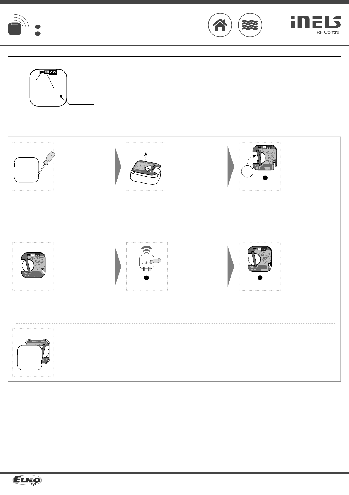
Instruction manual is designated for mounting and also for user of the device. It is always a part of its packing.
Installation and connection can be carried out only by a person with adequate professional qualification upon
understanding this instruction manual and functions of the device, and while observing all valid regulations.
Trouble-free function of the device also depends on transportation, storing and handling. In case you notice any
sign of damage, deformation, malfunction or missing part, do not install this device and return it to its seller. It
is necessary to treat this product and its parts as electronic waste after its lifetime is terminated. Before starting
installation, make sure that all wires, connected parts or terminals are de-energized. While mounting and servicing
observe safety regulations, norms, directives and professional, and export regulations for working with electrical
devices. Do not touch parts of the device that are energized – life threat. Due to transmissivity of RF signal, observe
correct location of RF components in a building where the installation is taking place. RF Control is designated only
for mounting in interiors. Devices are not designated for installation into exteriors and humid spaces. The must not
be installed into metal switchboards and into plastic switchboards with metal door – transmissivity of RF signal is
then impossible. RF Control is not recommended for pulleys etc. – radiofrequency signal can be shielded by an
obstruction, interfered, battery of the transceiver can get flat etc. and thus disable remote control.
Warning
Accessories /
Flood sensor FP-1
• the flood sensor is designed to detect flooding, especially in residential areas, over flowing
bathes, disorders of washing machines, dishwashers, boilers, etc.
SHR-1-M: brass sensor
SHR-1-N: stainless steel sensor
• sensor to control flooding
Level probe SHR-2
• detection sensor is electrode, which in connection with switchable device is used for level
detection for example in wells,tanks...
Measuring probe /
Technical parameters /
Supplyvoltage:
Battery life:
Indication of transmission/function:
Reset after ooding:
Programming:
Measuring input:
Voltageat measuring input:
Resistance at measuring input for
ood detection:
Resistance at measuring input for
run-o detection:
Probe wire length:
Frequency:
Signal transmission method:
Rangein the open:
Other data
Working temperature:
Working position:
Fixing:
Degree of protection:
Pollution degree:
Dimensions:
Weight:
Relating standards:
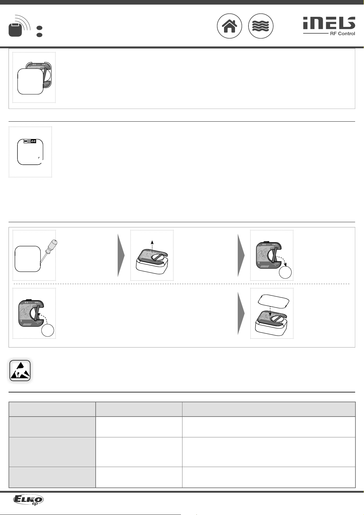
Attention:
When you instal iNELS RF Control system, you have to keep minimal distance 1 cm between each units.
Between the individual commands must be an interval of at least 1s.
Detector inalámbrico de inundaciones
ES
ELKO
EP
,
s.r
.o.
|
Palackého
493
|
769
01
Holešov
,
V
šetuly
|
Czech
Republic
|
e-mail:
[email protected] |
Support:
+420
778
427
36
6ELKO
EP
ESP
AÑA,
S.L.
|
C/
Josep
Martinez
15a,
bj
|
07007
Palma
de
Mallorca
|
e-mail:
[email protected] |
T
el.:
+34
971
751
425
|
F
ax:
+34
971
428
076
www.elkoep.com / www.elkoep.es
Accesorios
Sondas de medición
Sonda de inundación FP-1
• sonda de inundación está destinada para detectar inundaciones, especialmente en las zonas
residenciales, bañeras desbordantes, trastornos de lavadoras, lavavajillas, calderas, etc.
Sonda de nivel SHR-1-M - sonda de latón
Sonda de nivel SHR-1-N - sonda de acero inoxidable
• sondas para controlar las inundaciones.
Sonda de nivel SHR-2
• sensor de detección es un electrodo, que en conexión con el dispositivo adecuado de control se
utiliza para detectar niveles ej. en pozos, tanques...
Especificaciones técnicas
Tensiónde alimentción:
Vida de batería:
Indicaciónde comunicación:
Reset después de inundación:
Programación:
Entrada de medición:
El voltajeen laentrada de medida:
Resistencia de laentrada de medida
para detectar inundaciones:
Resistencia alamedición
desinundación:
Longitud máxima de cable:
Frecuencia:
Modo de transmisiónde señal:
Alcance al aire libre:
Más información
Temperatura de funcionamiento:
Posiciónde funcionamiento:
Montaje:
Protección:
Grado de contaminación:
Dimensiones:
Peso:
Normas conexas:
1x 3Vbatteries / bateríaCR 2477
1year / año
red / rojoLED
JUMPER -manual/automatic / manual/automático
with Prog button/based batteries / botónProg/insertar labatería
terminal / terminales 0.5-1mm2
3V
≤ 20 kΩ
≥ 40kΩ
max.30m
866 MHz, 868 MHz, 916 MHz
bi-directional addressed message/
mensajedirigida bidireccionalmente
up to / hasta 160 m
-10...+50 °C
any / cualquiera
glue, screws/ pegado, libre
IP30
2
49x 49x 13 mm
45g
EN 60730-1,
EN 300 220, EN 301 489 directive R&TTE Directive, Order. No426/2000 Coll.(Directive 1999/
EC) /
EN 60730-1, EN 300 220, EN 301 489 directiva RTTE, NVč.426/2000Sb(directiva1999/ES)
El manual de uso está dirigido para la instalación y el usuario del dispositivo. Manual siempre está incluido en
embalaje. La instalación y conexión puede realizar sólo personal con adecuadas cualificaciones profesionales, de
conformidad con todas las regulaciones aplicadas, y que está perfectamente familiarizado con estas instrucciones
y funciones del dispositivo. Función del dispositivo también depende del transporte, almacenamiento y la
manipulación. Si se observa cualquier signo de daño, deformación, mal funcionamiento o pieza que falta, no instale
este producto y devolvelo al vendedor. Con el producto y sus componentes debe ser tratado después de su vida
útil como con residuos electrónicos. Antes de iniciar la instalación, asegúrese de que todos los cables, partes o
terminales conectados están sin la conexión a la red. En el montaje y el mantenimiento se deben observar las
normas de seguridad, normas, directivas y reglamentos para trabajar con equipos eléctricos. No toque las partes
del dispositivo que están conectadas en la red - puede producir peligro de vida. Debido a la transmisibilidad de la
señal RF, observe la correcta ubicación de los componentes RF en un edificio donde la instalación se lleva a cabo. RF
Control está diseñado para montaje en interiores, las unidades no están diseñados para la instalación en exteriores
y espacios húmedos, no se pueden instalar en cuadros eléctricos de metal y en cuadros eléctricos plásticos con
puerta de metal - lo que empeora transmisividad de la señal RF. RF Control no se recomienda para el control de
dispositivos que ofrecen funciones vitales o para controlar dispositivos tales como bombas, el. calentadores sin
termostato, ascensores, montacargas, etc. - Señal de radiofrecuencia puede estar bloqueado por una obstrucción,
interferida, la batería del controlador puede estar ya sin energía, etc. y por lo tanto el control remoto puede ser
incapacitado.
Advertencia
Advertencia:
En la instalación de iNELS RF Control debe haber una distancia mínima entre las diferentes unidades
de un centímetro.
Entre los diferentes ordenes debe pasar al menos 1s.