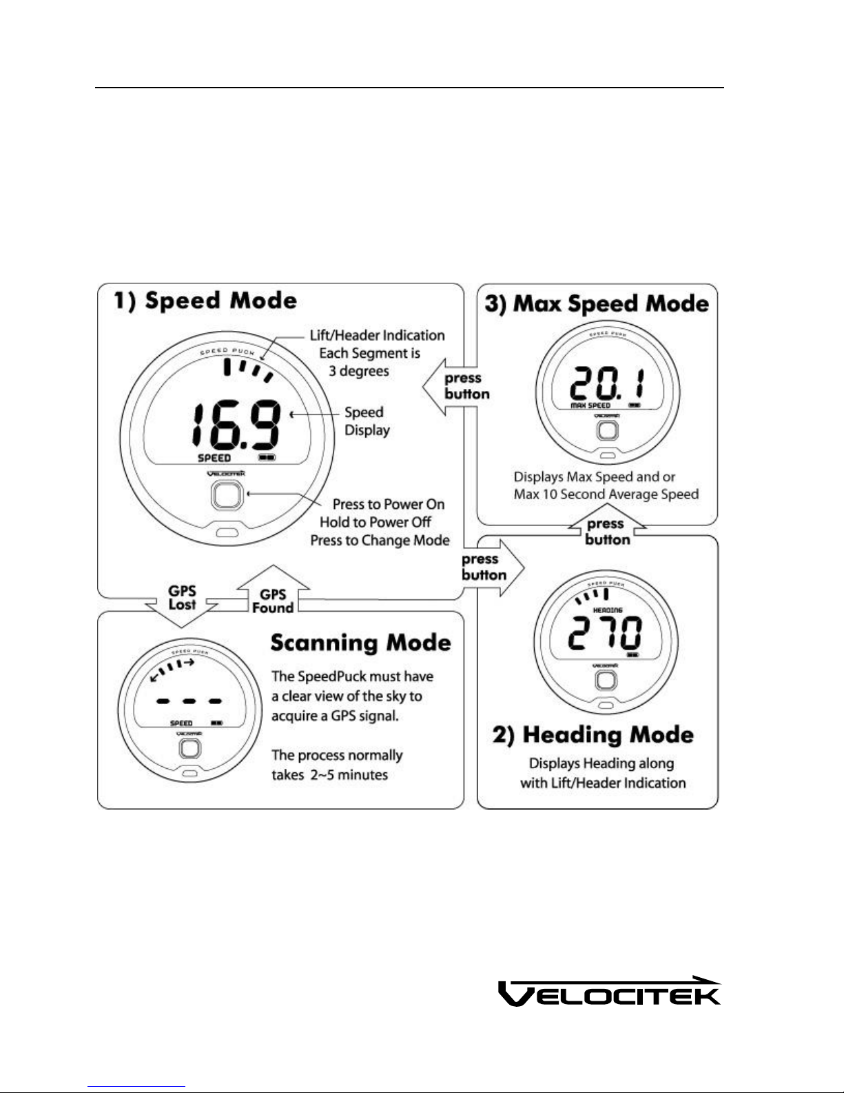
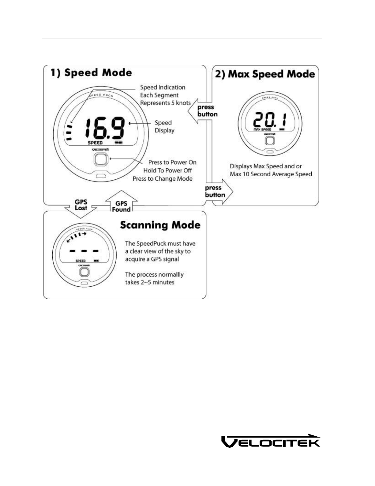
Velocitek SpeedPuck User manual

SpeedPuck Manual
Firmware Version v1.51
Revision Date April 4, 2018

Contents
INTRODUCTION 1
FEATURES 1
BASICS 2
BATTERIES 2
BATTERY INSTALLATION 2
BATTERY INDICATOR 2
BATTERY TYPES 2
SIGNAL ACQUISITION 3
INSTALLATION GUIDE 3
GPS DATA STORAGE 3
OPERATION 4
SAILING OPERATION 4
RACE OPERATION 5
MOTOR SPORTS OPERATION 6
DATA LOGGER OPERATION 7
DISPLAYS 8
SPEED 8
HEADING 8
MAX SPEED 8
LIFT/HEADER BAR GRAPH INDICATOR 8
SPEED BAR GRAPH INDICATOR 9
CONFIGURATION 10
DEVICE SETTINGS 10
DEVICE OPERATION 10
LOGGING RATE 10
SPEED DISPLAYED IN10
MAX SPEED DISPLAY 10
SPEED AND HEADING DAMPING 10
BAR GRAPH DISPLAY 11

COMPASS DECLINATION 11
FIRMWARE UPDATE 11
SOFTWARE 12
VELOCITEK CONTROL CENTER 12
VELOCITOOL 12
MAINTENANCE 13
CONTACT 14
COMPLIANCE 15
FCC COMPLIANCE STATEMENT 15
CANADIAN COMPLIANCE STATEMENT 15
EUROPEAN COMMUNITY COMPLIANCE STATEMENT 15
INDEX 16

Features 1
Introduction
The SpeedPuck is a GPS device designed for sailing and motor sports.
Features
Speed and compass updated twice a second
Header/Lift indicator updated twice a second
Maximum and best 10 second average speed recall
Over 20 hours of GPS data storage at record rate of every 2 seconds
Up to 20 hours of battery life (batteries not included)
Data downloading through USB link
User configurable device settings allow customization of select functions
Waterproof to 3m (IPX8)
Two year warranty

Basics 2
Basics
Batteries
Battery Installation
The SpeedPuck requires 3 AA batteries to operate. The battery compartment can be reached by
opening the back case.
Battery Indicator
The battery indicator on the SpeedPuck is located on the bottom right of the LCD screen.
Battery Types
We recommend using rechargeable batteries over standard disposable AA batteries. Disposable
batteries will provide approximately 10 hours of life while rechargeable batteries will last for 20 hours or
longer.

Basics 3
Signal Acquisition
The operation of the SpeedPuck relies on low-power radio signals from GPS satellites that orbit the earth
at an altitude of approximately 20,000 km. As a result, the SpeedPuck must be outdoors with a clear
view of the sky to function properly.
When the SpeedPuck is first turned on, it must download information from GPS satellites before it can
acquire a GPS solution. The data download process normally takes 1-2 minutes or up to 5 minutes if
fresh batteries have just been installed.
Installation Guide
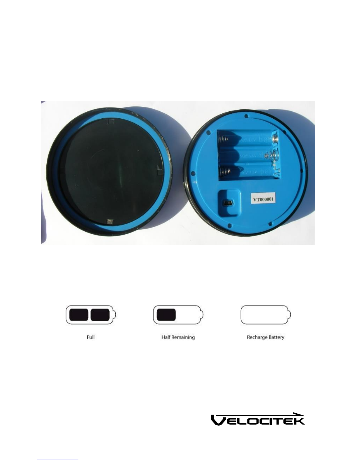
The SpeedPuck can be installed anywhere on the boat with a view of the sky. The SpeedPuck comes
with an injection molded plastic clip in cradle for easy installation. Install the cradle permanently on
your boat. Press the tab on the cradle to release the SpeedPuck from it. Since the introduction of the
SpeedPuck Cradle, the SpeedPuck no longer comes with the 3M Dual Lock on the back of the battery
compartment lid. Several alternative mounting options are available, including 3M Dual Lock. For
details, go to https://www.velocitek.com/collections/accessories.
GPS Data Storage
The SpeedPuck records GPS data whenever the device is on and GPS signal is detected. The device can
be configured to record data every second, every 2 seconds or every 4 seconds. The SpeedPuck can
store up to 20 hours of data when recording GPS data every 2 seconds.

Operation 4
Operation
This section will be split by SpeedPuck utility. The SpeedPuck can be configured by editing the device
operation option to suit a utility. The SpeedPuck has 4 operation options, sailing, racing, motor sports
and data logger which can be configured by editing the device settings.
Sailing Operation
The sailing operation is for those racing dinghy boats. All modes are enabled for maximum
performance.

Operation 5
Race Operation
The race operation is for racing in one design classes where the rules ban the use of a speedometer.
The SpeedPuck only works as a GPS compass in race operation to conform to one design rules.

Operation 6
Motor Sports Operation
The motor sports operation option is for the motor sports enthusiasts who want to know exactly how
fast they are going. No heading information is displayed in this operation as speed is the focus. The
bar graph acts as a secondary speedometer in speed mode so you know how fast you are going at a
glance.

Operation 7
Data Logger Operation
The data logger operation option is available in case rules prevent you from using the features offered by
the SpeedPuck. The data logger mode displays blank, but records your GPS data which can be replayed
later for analysis.

Operation 8
Displays
Following are details on the various displays.
Speed
Speed is calculated by the GPS unit by measuring the Doppler shift in GPS signals. It can be displayed in
knots, miles/hour, kilometers/hour or meter/second by editing the device settings. The default is
knots.
Heading
Heading (Course Over Ground) is calculated by the GPS unit by measuring the Doppler shift in GPS
signals.
Either true or magnetic heading can be displayed in compass mode by configuring the device settings.
True heading is referenced to true north. Magnetic heading is referenced to the local magnetic north.
When using a magnetic compass in conjunction with the SpeedPuck, the magnetic heading is useful since
both measurements will be referenced to magnetic north. By default the compass displays true
heading. To display magnetic heading the local magnetic declination must be defined in device
settings.
The SpeedPuck displays heading only when your speed is greater than 1 knot, otherwise it will show a
heading of 0 degrees regardless of which direction you are actually moving.
The difference of the SpeedPuck to a conventional magnetic compass is that the SpeedPuck measures
the direction the device is moving in rather than the direction it is pointed in. A major benefit of the
SpeedPuck over a conventional magnetic compass is that it will give you accurate heading information,
regardless of the orientation in which it is mounted on your boat. SpeedPuck 's compass reading
depends only on the direction you are moving, not the direction the device is pointing.
Max Speed
Instantaneous and or 10 second average max speed can be displayed. The max speed mode can be set
to display, the maximum instantaneous speed, the maximum 10 second average speed or flash between
both. To configure max speed display, edit the device settings.
Lift/Header Bar Graph Indicator
The SpeedPuck automatically detects when a sailor is trimmed to a heading then provides the header/lift
indication. When the device detects that the sailor is trimmed at a heading the trim angle is set. Then
header/lift indication is given off of that trim angle. Once a tack or a jibe is detected the indicator
resets and nothing is indicated until another trim angle is set. Each bar segment represents 3 degrees
of wind shift.

Operation 9
Speed Bar Graph Indicator
The Speed Bar Graph Indicator displays a bar graph with each bar segment representing 5 knots.

Configuration 10
Configuration
The SpeedPuck can be configured by editing the device settings by connecting it to a PC via USB cable.
Device Settings
The following device settings are available.
Device Operation
The device operation should be set depending on the SpeedPuck utility. The 4 operation options
available are sailing, race, motor sports and data logger. Each of these options tailors the SpeedPuck
functionality to the utility. For details on operation options refer to Operation.
Logging Rate
Logging rate is the rate at which the SpeedPuck records data. User can select from 1Hz (once every
second), 1/2Hz (once every 2 seconds), and 1/4Hz (once every 4 seconds). The default logging rate is
1/2Hz
Speed Displayed In
Speed can be displayed in 4 different units of measurement, knots, miles/hour, kilometers/hour and
meters/second. The default unit of measurement is knots.
Max Speed Display
There are 3 different maximum speed display modes you can choose from. Display maximum 10
second speed, maximum instantaneous speed and flash between both maximum speeds. The default is
to display maximum 10 second speed.
Speed and Heading Damping
Damping on the SpeedPuck corresponds to the amount of time to which the raw GPS data is averaged
over before it is displayed. Damping has the effect of smoothing out the displayed data while low
damping allows the displayed data to update faster.
High damping is good for evaluating different trim settings as it smoothes out spikes in the
measurements resulting from gusts and wave action. On the other hand, low damping will help you to
quickly identify the effect of gusts and wind shifts.
The damping on the SpeedPuck can be set for speed and heading independently to 10 different settings,
from no damping to damping of 4 minutes. The default damping is 1 second for both speed and
heading damping.

Configuration 11
We recommend that you experiment with different damping levels. The optimal setting will depend on
your boat, the conditions and what you are using the instrument for.
Bar Graph Display
Option to turn the display on or off is available when the sailing device operation option is selected.
Compass Declination
When defined to the local declination, the heading will be referenced to local magnetic north. Positive
declination represents east and negative declination represents west. To reference the compass
measurement to true north, input 0 for compass declination. Default compass declination is 0 degrees.
When using a magnetic compass in conjunction with the SpeedPuck, setting the compass declination to
the local declination is useful since both instruments will be referenced to magnetic north.
Firmware Update
Firmware is the software that runs on the SpeedPuck. The SpeedPuck firmware is stable and no
features or performance will be added to your device through a firmware update. We only release new
firmware versions when we are forced to do so by a minor hardware change. Please do not update the

Software 12
Software
There are two software packages, Velocitek Control Center (Windows and Mac) available from Velocitek
which allow you to perform GPS data download, customize device functionality and update firmware.
Velocitek Control Center / Velocitool
Velocitek Control Center and Velocitool are free software. To find out more and download the
software, go to http://www.velocitek.com/support/software.

Maintenance 13
Maintenance
To ensure your SpeedPuck's enclosure remains watertight and the electronics are not destroyed by
corrosion, please take the following precautions:
Dry case with a towel before opening.
Wipe away sand or debris on the gasket before screwing the back case on.
Once the case is open wipe away any loose water droplets.
If you ever see signs that water is leaking inside the enclosure please contact Velocitek
immediately at (866)-498-6737 or support@velocitek.com to arrange for your device to be
repaired and made watertight again.

Contact 14
Contact
Mail: Velocitek, Inc.
126 N B Street
San Mateo, CA 94401
USA
Fax: +1-650-618-2679
Phone: Calls will be answered 9AM ~ 6PM, US Eastern Time (UTC-4 Summer, UTC-5 Winter)
US and Canada: +1-866-498-6737
International: +1-650-529-4519
Email: [email protected]m
Website: http://www.velocitek.com
Support: http://www.velocitek.com/support

Compliance 15
Compliance
FCC Compliance Statement
This device complies with Part 15 of the FCC Rules. Operation is subject to the following two conditions:
(1) This device may not cause harmful interference, and (2) this device must accept any interference
received, including interference that may cause undesired operation.
NOTE: This equipment has been tested and found to comply with the limits for a Class B digital device,
pursuant to Part 15 of the FCC Rules. These limits are designed to provide reasonable protection against
harmful interference in a residential installation. This equipment generates, uses and can radiate radio
frequency energy and, if not installed and used in accordance with the instructions, may cause harmful
interference to radio communications. However, there is no guarantee that interference will not occur in
a particular installation. If this equipment does cause harmful interference to radio or television
reception, which can be determined by turning the equipment off and on, the user is encouraged to try
to correct the interference by one or more of the following measures:
Reorient or relocate the receiving antenna
Increase the separation between the equipment and receiver
Connect the equipment into an outlet on a circuit different from that to which the receiver is
connected
Consult the dealer or an experienced radio/TV technician for help
Canadian Compliance Statement
This Class B digital apparatus complies with Canadian ICES-003.
European Community Compliance Statement
The equipment complies with The EMC Directive 2004/108/EC.

Index 16
Index
B
Batteries, 2
C
Compliance, 15
Contact, 14
Control Center, 12
D
Device Setting
Bar Graph Display Option, 11
Compass Declination, 11
Device Operation, 10
Logging Rate, 10
Max Speed Display, 10
Speed and Heading Damping, 10
Speed Displayed In, 10
Device Settings, 10
Displays, 8
F
Firmware Update, 11
G
GPS Data Storage, 3
H
Heading, 8
I
Installation Guide, 3
L
Lift/Header Bar Graph Indicator, 8
M
Maintenance, 13
Max Speed, 8
O
Operation Option
Data Logger, 7
Operation Option
Motor Sports, 6
Sailing, 4
R
Race Operation, 5
S
Signal Acquisition, 3
Software, 12
Speed, 8
Speed Bar Graph Indicator, 9
Other manuals for SpeedPuck
2
Table of contents
Popular Marine Equipment manuals by other brands

Seastar Solutions
Seastar Solutions Optimus Seastation Quick reference guide

Simrad
Simrad Maris ECDIS900 Technical manual

MORLEY-IAS
MORLEY-IAS MI-WSO-XX-I Installation instructions and operators manual

Bennett
Bennett BOLT Control BCI8000 Installation and quick start manual

Furuno
Furuno FE-700 Operator's manual

Argus
Argus CWS100-AV instruction manual