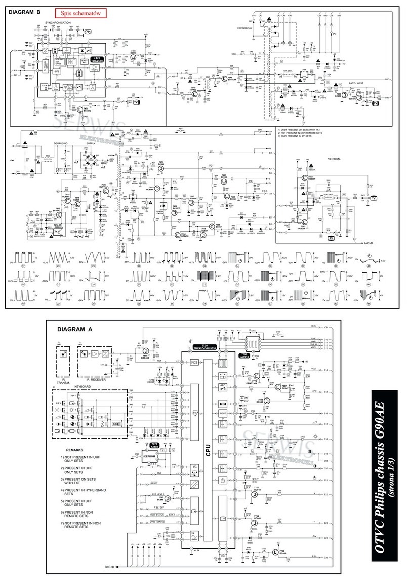
the PROT-UP line Low. If Horizontal drive or
EW Drive is lost, 7470 is turned On, applying
a positive voltage to the base of 7478, turning
it On. Transistor 7480 turns Off, causing the
PROT-UP line to go High through resistor
3480, which will cause the Microprocessor to
turn the set Off.
When the Driver Transistor 7481 is
conducting, the voltage drop across resistors
3404, 3405, and 3406 turns transistor 7408
On. This circuit supplies the 33 volt tuning
voltage and bias voltage to the IBEAM (Dag)
circuit. Transistor 7440 also detects the
failure of Horizontal Drive or Overcurrent. If
there is no Horizontal drive to 7481, 7408 will
turn Off, removing the 33 volt tuning voltage.
Transistor 7440 will turn On, causing the
PROT-UP to go High, which will cause the set
to shut Off. Voltage from Pin 5 of the IFT is
rectified by 6461 and applied to 7464. If this
voltage exceeds 5.4 volts, 7464 will turn On,
turning 7467 On, applying the +8 volt supply
to the PROTN line, shutting the set Off. The
IFT produces a plus and minus 13 volt supply
for the Vertical Output circuit. The voltage on
Pin 9 of the IFT is rectified by 6445 to produce
a +200 volt supply for the CRT output
circuit. The Horizontal Drive signal is
sampled by 3411, 3412, and 3413 to
produce the HFB (Horizontal Feedback
signal) which is used to provide Sync for
the Small Signal Board.
Vertical Output (Figure 7)
Positive and Negative Vertical drive from
the Small Signal Board is fed to the
Vertical Output IC7501 which drives the
Vertical Yoke. The Vertical Pulse on Pin3
drives 7513 to produce the VFB (Vertical
Feedback signal) for the Small Signal
Board. A failure in the Vertical Output
circuit will be detected by the Signal
Processor on the SSB by sensing the
Frame Drive line and by the
Microprocessor sensing the loss of the
VFB pulse. While turning the set On,
check the plus and minus 13 volt sources.
Then check for Vertical Drive on Pin 7 with
an oscilloscope while turning the set On.
Page 8
VIDEO SIGNAL FLOW
There are four variations in the signal flow
path for the H8 chassis. They are the Non-
PIP, the Single Tuner PIP, the Dual Tuner PIP,
and the Double Window version.
NON PIP Video Signal Flow (Figure 8)
The first version to be discussed is the Non
PIP chassis video path. The Main Tuner, AV1,
AV2, and Component Inputs are located on
the Large Signal panel. The AV3 input is
located on the Side Jack Panel. All of
these inputs are fed to the Small Signal
Board, SSB, which plugs into the Large
Signal panel. The Tuner IF is fed to the
SAW filter, 1451, and then to the Signal
Processor, 7301, on Pins 1 and 2.
Composite Video is output on Pin 16 and is
buffered by 7305 and 7331. Baseband
Audio is output on Pin 27 and is buffered
by 7307. This signal is fed to the Sound
Decoder IC for processing. The Video
Signal is then fed to 7301 on Pin 24 which
selects between the composite signal and
