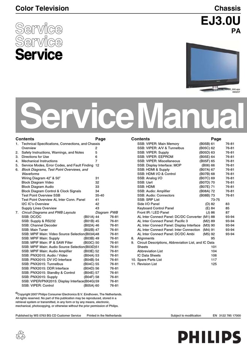
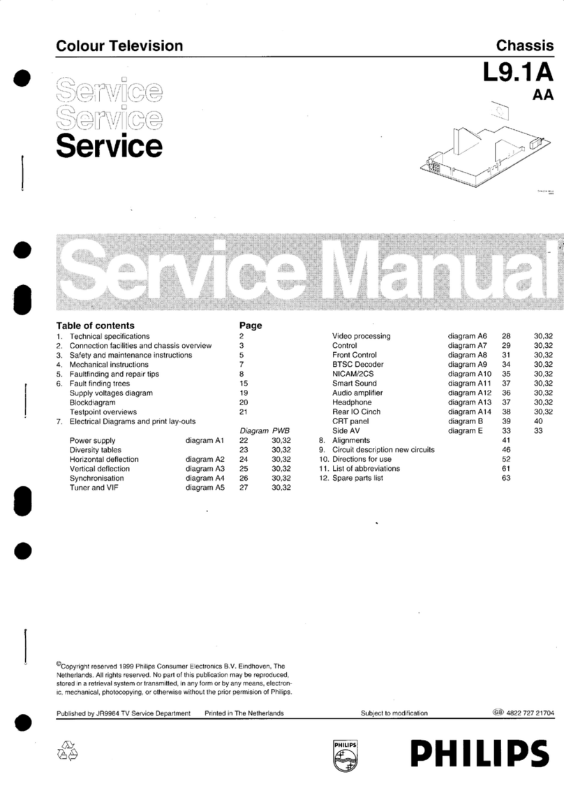
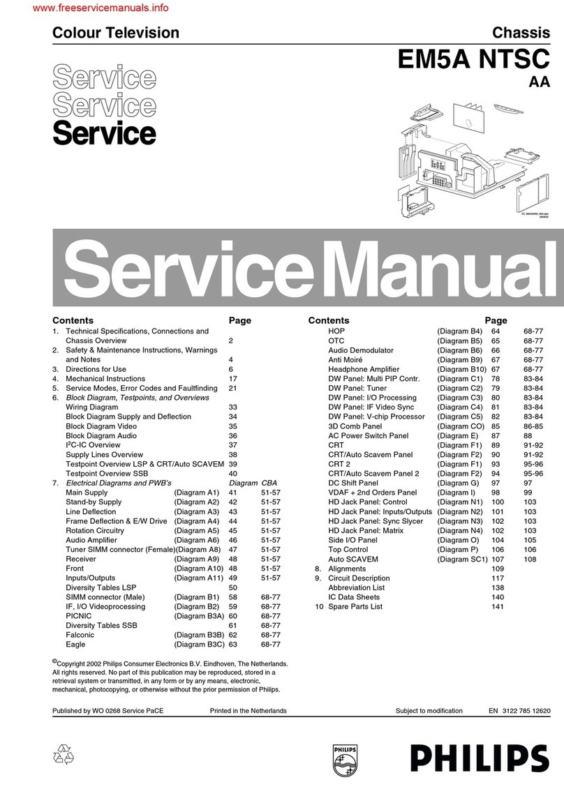
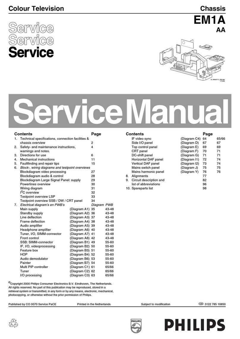
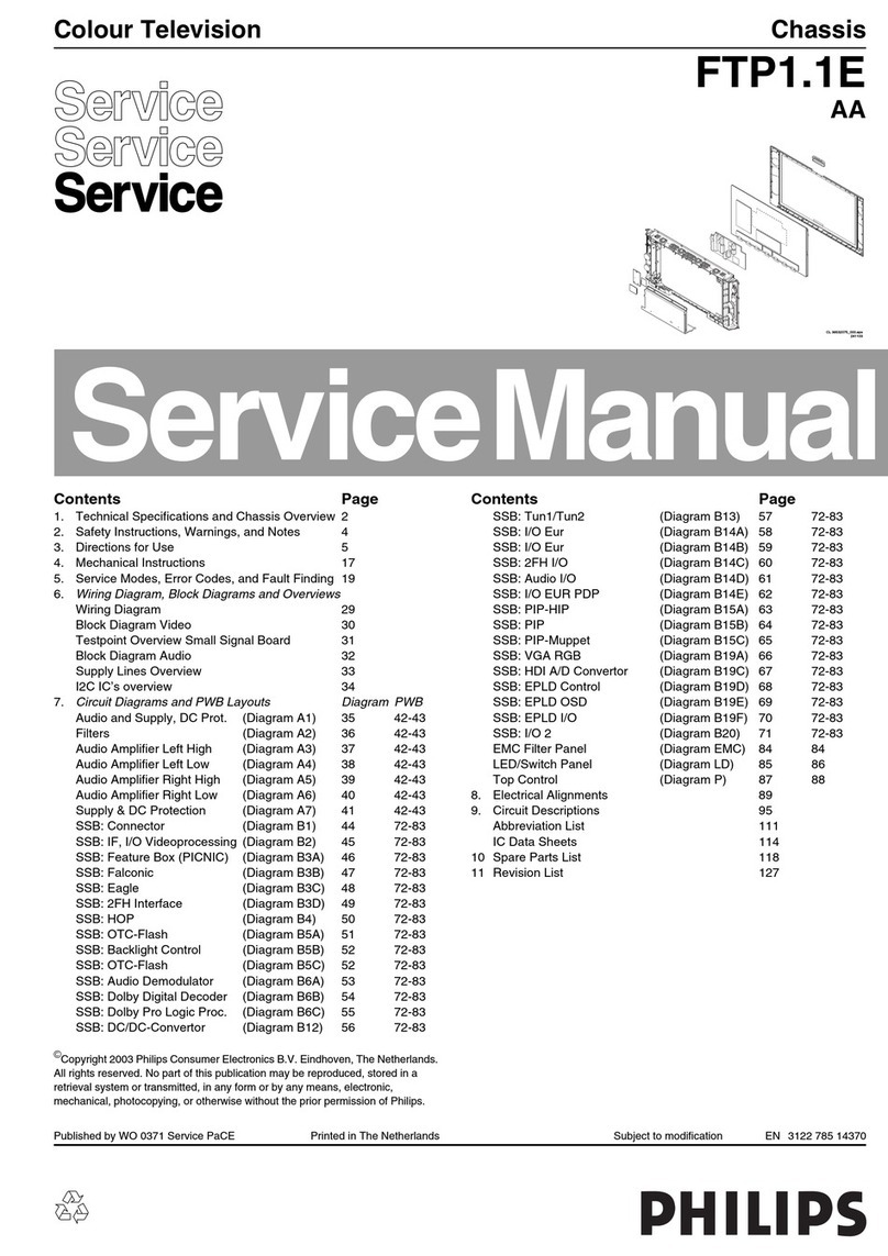
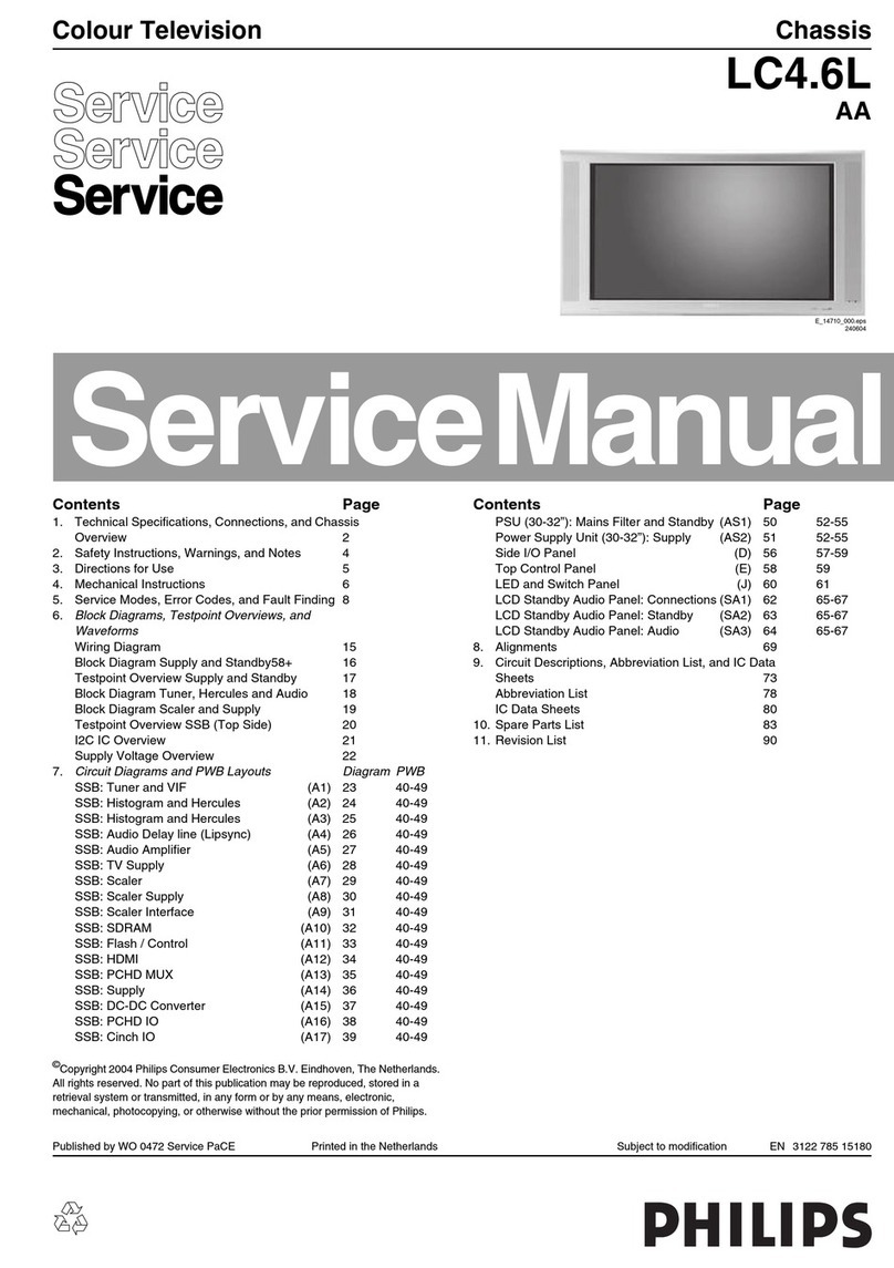
Philips L01.1L AC User manual

Published by RB 0363 Service PaCE Printed in the Netherlands Subject to modification EN 3122 785 13230
©
Copyright 2003 Philips Consumer Electronics B.V. Eindhoven, The Netherlands.
All rights reserved. No part of this publication may be reproduced, stored in a
retrieval system or transmitted, in any form or by any means, electronic,
mechanical, photocopying, or otherwise without the prior permission of Philips.
Colour Television Chassis
L01.1L
AC
Contents Page Contents Page
1. Technical Specifications, Connections, and
Chassis Overview 2
2. Safety and Maintenance Instructions, Warnings,
and Notes 4
3. Directions for Use 6
4. Mechanical Instructions 18
5. Service Modes, Error Codes, and Faultfinding 20
6. Block Diagram, I2C, Supply Voltage, and
Testpoint Overviews
Block Diagram 25
I2C and Supply Voltage Diagram 26
Testpoint Overview Mono Carrier & CRT Panel 27
7. Electrical Diagrams and PWB’s Diagram CBA
Power Supply (Diagram A1) 28 43-48
Line Deflection (Diagram A2) 29 43-48
Frame Deflection (Diagram A3) 30 43-48
Tuner IF (Diagram A4) 31 43-48
Video IF + Sound IF (Diagram A5) 32 43-48
Synchronisation (Diagram A6) 33 43-48
Control (Diagram A7) 34 43-48
Audio Amplifier (Diagram A8) 35 43-48
NICAM, 2CS, BTSC Stereo Dec.(Diagram A9) 36 43-48
Audio/Video Source Switch (Diagram A10) 37 43-48
BTSC-NDBX Stereo Decoder (Diagram A11) 38 43-48
Front IO, Front Control and HP (Diagram A12) 39 43-48
Rear IO Cinch (Diagram A13) 40 43-48
PIP + Tilt Interface (Diagram A16) 42 43-48
Diversity Tables 41
CRT Panel: ECO Scavem (Diagram B1) 49 51-52
CRT Panel: ECO Scavem (Diagram B2) 50 51-52
Side AV Panel + Headphone (Diagram C) 53 53
Side AV Panel + HP (SLIM) (Diagram C1) 54 55
Side AV Panel + HP (WIDE) (Diagram C2) 56 57
Top Control Panel (Diagram E) 58 58
Matrix Surround Panel (Diagram M) 59 59
Top Control Panel (Diagram T) 60 61
Front Interface Panel (Diagram Q1) 62 62
DAF Panel +
Inner Pin Cushion Correction (Diagram W) 63 63
8. Alignments 65
9. Circuit Description 71
Abbreviation List 80
IC Data Sheets 81
10 Spare Parts List (not applicable yet) 82
11 Revision List 83

Technical Specifications, Connections, and Chassis Overview
EN 2 L01.1L AC1.
1. Technical Specifications, Connections, and Chassis Overview
1.1 Technical Specifications
1.1.1 Reception
Tuning system : PLL
Colour systems : NTSC M
: PAL M
: PAL N
Sound systems : FM-mono
: BTSC + SAP
: BTSC non-DBX
A/V connections : PAL B/G (pb)
Channel selections : 181 channels
: Full cable
IF frequency : 45.75 MHz
Aerial input : 75 Ohm
:F-type
1.1.2 Miscellaneous
Audio output : 2 x 5 W or
: 2 x 10 W
Mains voltage : 90 - 276 V (±10 %)
Mains frequency : 50 / 60 Hz (±5 %)
Ambient temperature : + 5 to + 45 deg. C
Maximum humidity : 90 % RH
Power consumption : 52 W (20") to
: 120 W (36")
Standby Power consumption : 1 W
1.2 Connections
1.2.1 Front/Side Connections and Front/Top Control
Figure 1-1 Front/Side connections and Front/Top control
Audio / Video In
1 - Video CVBS 1 Vpp/75 Ohm
2 - Audio L 0.2 Vrms/10 kOhm
3 - Audio R 0.2 Vrms/10 kOhm
4 - Headphone 8 - 600 Ohm, 4 mW
1.2.2 Rear Connections
Figure 1-2 Rear connections
Monitor Out
1 - Video CVBS 1 Vpp/75 Ohm
2 - Audio L 0.5 Vrms/1 kOhm
3 - Audio R 0.5 Vrms/1 kOhm
AV1 YUV In(if present)
1 - Y 0.7 Vpp/75 Ohm
2 - U 0.7 Vpp/75 Ohm
3 - V 0.7 Vpp/75 Ohm
AV1 In
1 - Video CVBS 1 Vpp/75 Ohm
2 - Audio L 0.5 Vrms/10 kOhm
3 - Audio R 0.5 Vrms/10 kOhm
AV2 In
1 - Video CVBS 1 Vpp/75 Ohm
2 - Audio L 0.5 Vrms/10 kOhm
3 - Audio R 0.5 Vrms/10 kOhm
AV2 In (SVHS)
1 - gnd
2 - gnd
3 - Y 1 Vpp/75 Ohm
4 - C 0.3 Vpp/75 Ohm
RED
LED
V+ ORV-
P-
P+
R AUDIO L
R AUDIO L
INSTALL/MENU
+ VOLUME -
CHANNEL
VIDEO CL 26532119_053.eps
181202
IR
TOP CONTROL SIDE I/O
FRONT CONTROL + FRONT I/O
VOLUME-+-+PROGRAM
P
V
L
R
Y
U
V
V
L
R
V
L
R SVHS
MONITOR
OUT
75 Ohm
FM
AV1
IN AV2
IN
CL 16532008_005.eps
120601

Technical Specifications, Connections, and Chassis Overview EN 3L01.1L AC 1.
1.3 Chassis Overview
Figure 1-3 PWB Location
SIDE AV PANEL +
HEADPHONE
C1
B2
B1
C2
C
MAIN
CHASSIS
PANEL
A1
T
E
A2
A3
A4
A5
A12
A9
A10
A11
A8
A13
POWER SUPPLY
Q1
FRONT INTERFACE PANEL
LINE DEFLECTION
FRAME DEFLECTION
A6
SYNCHRONISATION
TUNER IF
VIDEO + SOUND IF
FRONT I/O + FRONT CONTROL
+ HEADPHONE
BTSC - NDBX DECODER
A7
CONTROL (µC)
NICAM + 2CS +
BTSC DECODER
A/V SOURCE SWITCHING
AUDIO AMPLIFIER
REAR I/O CINCH
CL 36532118_004.eps
140303
A16
TILT INTERFACE
TOP CONTROL PANEL
"SLIM"
CRT PANEL
W
DAF PANEL
M
MATRIX
SURROUND
PANEL
CRT
SCAVEM
"WIDE"

Safety & Maintenance Instructions, Warnings, and Notes
EN 4 L01.1L AC2.
2. Safety & Maintenance Instructions, Warnings, and Notes
Index of this chapter:
1. Safety Instructions for Repairs
2. Maintenance Instructions
3. Warnings
4. Notes
2.1 Safety Instructions for Repairs
Safety regulations require that during a repair:
• Due to the 'hot' parts of this chassis, the set must be
connected to the AC power via an isolation transformer.
• Safety components, indicated by the symbol , should be
replaced by components identical to the original ones.
• When replacing the CRT, safety goggles must be worn.
Safety regulations require that after a repair, the set must be
returned in its original condition. Pay particular attention to the
following points:
• General repair instruction: as a strict precaution, we advise
you to resolder the solder connections through which the
horizontal deflection current is flowing, in particular:
– all pins of the line output transformer (LOT)
– fly-back capacitor(s)
– S-correction capacitor(s)
– line output transistor
– pins of the connector with wires to the deflection coil
– other components through which the deflection current
flows.
Note: This resoldering is advised to prevent bad connections
due to metal fatigue in solder connections and is therefore only
necessary for television sets more than two years old.
• Route the wire trees and EHT cable correctly and secure
them with the mounted cable clamps.
• Check the insulation of the AC power cord for external
damage.
• Check the strain relief of the AC power cord for proper
function, to prevent the cord from touching the CRT, hot
components, or heat sinks.
• Check the electrical DC resistance between the AC plug
and the secondary side (only for sets that have an isolated
power supply). Do this as follows:
1. Unplug the AC power cord and connect a wire between
the two pins of the AC plug.
2. Turn on the main power switch (keep the AC power
cord unplugged!).
3. Measure the resistance value between the pins of the
AC plug and the metal shielding of the tuner or the
aerial connection of the set. The reading should be
between 4.5 MOhm and 12 MOhm.
4. Switch the TV 'off' and remove the wire between the
two pins of the AC plug.
• Check the cabinet for defects, to prevent the possibility of
the customer touching any internal parts.
2.2 Maintenance Instructions
It is recommended to have a maintenance inspection carried
out by qualified service personnel. The interval depends on the
usage conditions:
• When the set is used under normal circumstances, for
example in a living room, the recommended interval is
three to five years.
• When the set is used in an environment with higher dust,
grease or moisture levels, for example in a kitchen, the
recommended interval is one year.
• The maintenance inspection includes the following actions:
1. Perform the 'general repair instruction' noted above.
2. Clean the power supply and deflection circuitry on the
chassis.
3. Clean the picture tube panel and the neck of the picture
tube.
2.3 Warnings
• In order to prevent damage to ICs and transistors, avoid all
high voltage flashovers. In order to prevent damage to the
picture tube, use the method shown in Fig. 2-1, to
discharge the picture tube. Use a high voltage probe and a
multi-meter (position Vdc). Discharge until the meter
reading is 0 V (after approx. 30 s).
Figure 2-1 Discharge picture tube
• All ICs and many other semiconductors are susceptible to
electrostatic discharges (ESD ). Careless handling
during repair can reduce life drastically. When repairing,
make sure that you are connected with the same potential
as the mass of the set by a wristband with resistance. Keep
components and tools also at this potential.
• Available ESD protection equipment:
– Complete kit ESD3 (small tablemat, wristband,
connection box, extension cable, and ground cable)
4822 310 10671.
– Wristband tester 4822 344 13999.
• Together with the deflection unit and any multi-pole unit,
flat square picture tubes form an integrated unit. The
deflection and the multi-pole units are set optimally at the
factory. Adjustment of this unit during repair is therefore not
recommended.
• Be careful during measurements in the high voltage
section and on the picture tube.
• Never replace modules or other components while the unit
is switched 'on'.
• When you align the set, use plastic rather than metal tools.
This will prevent any short circuits and the danger of a
circuit becoming unstable.
2.4 Notes
2.4.1 General
• Measure the voltages and waveforms with regard to the
chassis (= tuner) ground (), or hot ground (), depending
on the area of circuitry being tested.
• The voltages and waveforms shown in the diagrams are
indicative. Measure them in the Service Default Mode (see
“Service Modes, Error Codes, and Faultfinding” section)
with a color bar signal and stereo sound (L: 3 kHz, R: 1 kHz
unless stated otherwise) and picture carrier at 61.25 MHz
(NTSC, channel 3).
• Where necessary, measure the waveforms and voltages
with () and without () aerial signal. Measure the
voltages in the power supply section both in normal
operation () and in standby (). These values are
indicated by means of the appropriate symbols.
V
CL96532156_040.eps
140501
Safety & Maintenance Instructions, Warnings, and Notes EN 5L01.1L AC 2.
• The picture tube panel has printed spark gaps. Each spark
gap is connected between an electrode of the picture tube
and the Aquadag coating.
• The semiconductors indicated in the circuit diagram and in
the parts lists are completely interchangeable per position
with the semiconductors in the unit, irrespective of the type
indication on these semiconductors.
2.4.2 Schematic Notes
• All Resistor values are in ohms and the value multiplier is
often used to indicate the decimal point location (e.g. 2K2
indicates 2.2 kOhm).
• Resistor values with no multiplier may be indicated with
either an 'E' or an 'R' (e.g. 220E or 220R indicates 220
Ohm).
• All Capacitor values are expressed in Micro-Farads (µ=
x10-6), Nano-Farads (n = x10-9), or Pico-Farads
(p = x10-12).
• Capacitor values may also use the value multiplier as the
decimal point indication (e.g. 2p2 indicates 2.2 pF).
• An 'asterisk' (*) indicates component usage varies. Refer to
the diversity tables for the correct values.
• The correct component values are listed in the Electrical
Replacement Parts List. Therefore, always check this list
when there is any doubt.
2.4.3 Practical Service Precautions
•It makes sense to avoid exposure to electrical shock.
While some sources are expected to have a possible
dangerous impact, others of quite high potential are of
limited current and are sometimes held in less regard.
•Always respect voltages. While some may not be
dangerous in themselves, they can cause unexpected
reactions - reactions that are best avoided. Before reaching
into a powered TV set, it is best to test the high voltage
insulation. It is easy to do, and is a good service precaution.
•Before powering up the TV set with the back cover off
(or on a test fixture), attach a clip lead to the CRT DAG
ground and to a screwdriver blade that has a well insulated
handle. After the TV is powered on and high voltage has
developed, probe the anode lead with the blade, starting at
the case of the High Voltage Transformer (flyback - IFT).
Move the blade to within two inches of the connector of the
CRT. If there is an arc, you found it the easy way,
without getting a shock! If there is an arc to the
screwdriver blade, replace the part which is causing the
problem; the High Voltage Transformer or the lead (if it is
removable).

Mechanical Instructions
EN 18 L01.1L AC4.
4. Mechanical Instructions
Index of this chapter:
1. Set Disassembly
2. Service Positions
3. Assy/Board Removal
4. Set Re-assembly
Note: Figures below can deviate slightly from the actual
situation, due to different set executions.
4.1 Set Disassembly
1. Remove all fixation screws of the rear cover (do not forget
the screws that hold the rear connection panel).
2. Now pull the rear cover backwards to remove it.
4.2 Service Positions
There are 2 configurations possible. With and without panel
bracket. Both have a different service position:
Main panel without bracket (with integrated 'control' part).
1. Disconnect the strain relief of the AC power cord.
2. Remove the main panel, by pushing the two center clips
outwards [1]. At the same time pull the panel away from the
CRT [2].
3. Disconnect the degaussing coil by removing the cable from
(red) connector 0212.
4. Turn the panel 90 degrees counter clockwise [3].
5. Flip the panel 90 degrees [4], with the components towards
the CRT.
6. Turn the panel with its rear connections towards the CRT
[5].
7. Slide the metal heatsink (near the mains transformer 5520)
underneath the right chassis bracket. This secures the
panel [6].
Figure 4-1 Service position (1)
Main panel with bracket (with separate 'control' part).
1. Disconnect the strain relief of the AC power cord.
2. Disconnect the degaussing coil by removing the cable from
(red) connector 0212 [1].
3. Remove the panel bracket from the bottom tray, by pulling
it backward [2].
4. Turn the chassis tray 90 degrees counter clockwise [2].
5. Move the panel somewhat to the left and flip it 90 degrees
[3], with the components towards the CRT.
6. Turn the panel with the rear I/O towards the CRT.
7. Place the hook of the tray in the fixation hole of the cabinet
bottom [4] and secure it.
Figure 4-2 Service position (2)
4.3 Assy/Board Removal
4.3.1 Comb Filter Assy/ Board (if present)
You can remove the Comb Filter panel from the Main Carrier
board, by disconnecting it from connector 1810 (located nearby
the mains transformer 5520).
B
1
A
CL 16532016_007.ai
040401
3
6
45
1
1
2
A
CL 16532016_009.eps
220501
B
4
3
2
1

Mechanical Instructions EN 19L01.1L AC 4.
4.3.2 Top Control Assy/Board (if present)
Figure 4-3 Top control removal
1. Remove the two fixation screws (if present).
2. Pull the module down and backwards (w.o.w. release it
from the front hinge [M]). You must use some force.
3. Lift the board from its bracket while releasing the two
fixation clamps. The board hinges on the other side.
4.3.3 Front Interface Assy/ Board (if present)
Figure 4-4 Front interface removal
1. You can remove the complete module from the bottom
plate, by pulling the two fixation clamps upwards [1] while
sliding the module away from the CRT [2].
2. Release the 2 fixation clamps [3] at the side of the bracket,
and lift the board out of the bracket (it hinges at one side).
4.3.4 DAF Assy/ Board (if present)
Figure 4-5 DAF panel removal
1. You can remove the complete module from the Main
Carrier bracket, by pressing its fixation clamp downwards
[1] while sliding the module in the direction of the CRT [2].
2. Release the 2 fixation clamps [3] to lift the board out of the
bracket [4].
4.3.5 Side I/O Assy/ Board (if present)
Figure 4-6 Side jack panel removal
1. You can remove the complete Side I/O assembly after
removing the 2 fixation screws.
2. Release the 2 fixation clamps to lift the board out of the
bracket.
4.4 Set Re-assembly
Before you mount the rear cover, perform the following checks:
1. Check whether the AC power cord is mounted correctly in
its guiding brackets.
2. Re-place the strain relief of the AC power cord into the
cabinet.
3. Check whether all cables are replaced in their original
position.
CL 06532012_003.eps
030200
M
Top control board
2
3
1
1
3
CL 06532130_018.eps
021000
CL 26532119_060.eps
181202
3
2
3
4
1
CL 06532012_004.eps
030200

Service Modes, Error Codes, and Fault Finding
EN 20 L01.1L AC5.
5. Service Modes, Error Codes, and Fault Finding
Index:
1. Test points.
2. Service Modes.
3. Problems and Solving Tips (related to CSM).
4. ComPair
5. Error Codes.
6. The Blinking LED Procedure.
7. Protections.
8. Repair Tips.
5.1 Test Points
The chassis is equipped with test points printed on the circuit
board assemblies. These test points refer to the functional
blocks:
Table 5-1 Test Point Overview
The numbering is in a logical sequence for diagnostics. Always
start diagnosing within a functional block in the sequence of the
relevant test points for that block.
Perform measurements under the following conditions:
• Service Default Alignment Mode.
• Video: color bar signal.
• Audio: 3 kHz left, 1 kHz right.
5.2 Service Modes
Service Default Alignment Mode (SDAM) offers several
features for the service technician, while the Customer Service
Mode (CSM) is used for communication between dealer and
customer.
There is also the option of using ComPair, a hardware interface
between a computer (see requirements) and the TV chassis. It
offers the ability of structured trouble shooting, error code
reading and software version readout for all chassis.
Requirements: To run ComPair on a computer (laptop or
desktop) requires, as a minimum, a 486 processor, Windows
3.1 and a CD-ROM drive. A Pentium Processor and Windows
95/98 are however preferred (see also paragraph 5.4).
Table 5-2 SW Cluster
5.2.1 Service Default Alignment Mode (SDAM)
Purpose
• To change option settings.
• To create a predefined setting to get the same
measurement results as given in this manual.
• To display / clear the error code buffer.
• To override SW protections.
• To perform alignments.
• To start the blinking LED procedure.
Specifications
• Tuning frequency: 61.25 MHz (channel 3) for NTSC-sets
(LATAM).
• Color system: PAL-M for LATAM BI/TRI/FOUR-NORMA.
• All picture settings at 50 % (brightness, color contrast,
hue).
• Bass, treble and balance at 50 %; volume at 25 %.
• All service-unfriendly modes (if present) are disabled, like:
– (Sleep) timer,
– Child/parental lock,
– Blue mute,
– Hotel/hospitality mode
– Auto switch-off (when no “IDENT” video signal is
received for 15 minutes),
– Skip / blank of non-favorite presets / channels,
– Auto store of personal presets,
– Auto user menu time-out.
• Operation hours counter.
• Software version.
• Option settings.
• Error buffer reading and erasing.
• Software alignments.
How to enter SDAM
Use one of the following methods:
• Use a standard customer RC-transmitter and key in the
code 062596 directly followed by the “M” (menu) button or
• Short jumper wires 9631 and 9641 on the mono carrier
(see Fig. 8-1) and apply AC power. Then press the power
button (remove the short after start-up).
• Caution: Entering SDAM by shorten wires 9631 and 9641
will override the +8V-protection. Do this only for a short
TEST POINT CIRCUIT DIAGRAM
A1-A2-A3-.. AUDIO PROCESSING A8,A9 / A11
C1-C2-C3-.. CONTROL A7
F1-F2-F3-.. FRAME DRIVE & OUTPUT A3
I1-I2-I3-.. TUNER & IF A4
L1-L2-L3-.. LINE DRIVE & OUTPUT A2
P1-P2-P3-.. POWER SUPPLY A1
S1-S2-S3-.. SYNCHRONISATION A6
V1-V2-V3-.. VIDEO PROCESSING A5,B1
SW Cluster Software
name
UOC type UOC Di-
versity
Special
Fea-
tures
L3LLS1 L01LS4 x.y TDA9599
(LS)
96K
ROM
Size
CC,
Stereo
dBx,
wide
screen ,
Dolby
EW
L3LLS2 L01LS5 x.y TDA9570
(LS)
55K
ROM
Size
CC,
Stereo
dBx
L3LLS3 L01LS3 x.y TDA9583
(LS)
64K
ROM
Size
CC,
Stereo
dBx,EW
L3LLN2 L01LN2 x.y TDA9570
(LS)
55K
ROM
Size
CC,
Stereo
non-
dBx
Abbreviations in Software name: L = Latam, M = Mono,
N = Stereo non-dBx and S = Stereo dBx.
Table of contents
Other Philips Chassis manuals

Philips
Philips FTV1.9EE User manual

Philips
Philips LC4.1E A User manual

Philips
Philips LC4.6L AA User manual

Philips
Philips DPTV565 AA User manual

Philips
Philips EM1A Building instructions

Philips
Philips L01H.1A User manual

Philips
Philips FTL13U User manual

Philips
Philips LC7.2E User manual

Philips
Philips FTP1.1E User manual

Philips
Philips L9.2E AA User manual

Philips
Philips TPM16.1E LA User manual

Philips
Philips L01.1A User manual

Philips
Philips LC4.5E User manual

Philips
Philips VES1.1E User manual

Philips
Philips L01.1A User manual

Philips
Philips QV14.1E User manual

Philips
Philips EM5.2E User manual

Philips
Philips TE1.1E User manual

Philips
Philips LC4.1HE User manual

Philips
Philips FTL2.4A User manual