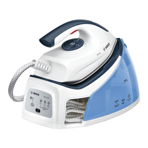
GC8560
5-7
DISASSEMBLY ADVICE - STAND
Disassemble TRAY RUBBER CAP FRONT 52
Disassemble TRAY RUBBER CAP REAR 51
Remove Screws J1, J2, J3
Disassemble TRAY 50
Remove Screws K1, K2
Disassemble STAND RIM, RUBBER FRONT LOCK 48
Remove Screws L1, L2, M1, M2 and
disengage all connectors on PCB
Disassemble DISPLAY PANEL PRINTED ASSY 47
Remove Screws U1, U2
Disassemble REAR LOCK ASSY 58
Note:
For re-assembling, sequence is STAND TOP first, then
DISPLAY PANEL PRINTED ASSY.
Disassemble INLET COUPLING PLATE
Disassemble RINSE CAP ASSY 55, RINSE BUSH,
RINSE RUBBER 53
Remove Screws M3, M4, N1, N2
Disassemble STAND TOP ASSY 43
Remove Screw P
Disassemble FLEX ASSY COMPARTMENT
Remove Screws Q1, Q2, Q3
Disassemble AUTO CORD WINDER ASSY 42
Remove Screws R1, R2
Remove Hose-cord clamp
Disassemble HOSE CORD CABLE ASSY 13
Note:
Take note of the orientation on the hose-cord clamp
Remove Screws S1, S2, S3, S4
Remove 2 x pump support plates
Remove Inox clamp at boiler inlet collar
Disengage 2 x wire connectors on PUMP ASSY 31
Disassemble PUMP ASSY 31
Remove Screws T1, T2
Remove Nut for Earth wires
Disassemble BOILER ASSY 39
PARTS LIST - STAND
Pos Service code Description
30
31
35
36
37
38
39
40
42
43
44
47
48
50
51
52
53
55
56
57
58
4239 021 48370
4239 021 48380
4239 010 10260
4239 015 58090
4239 026 32180
4239 026 31640
4239 021 49090
4239 017 09890
4239 021 48550
4239 021 49912
4239 021 48410
4239 021 48570
4239 021 57121
4239 015 58120
4239 021 48480
4239 015 58180
4239 015 58160
4239 015 58140
4239 021 48430
4239 021 57651
4239 021 48540
4239 021 49950
Stand bottom assy
Pump assy
Inox clamp
Boiler rubber support
Spacer bottom
Spacer top
Boiler assy
Electrovalve
Auto cord winder mounted assy EU
Auto cord winder mounted assy UK
Stand top assy
Hall sensor PCBA assy
Display panel printed assy
Rubber front lock
Tray sprayed
Tray rubber cap rear
Tray rubber cap front
Rinse rubber
Rinse cap assy
Tank assy
Iron mat assy
Rear lock assy - High End
= changed


