DNG485 Instruction Manual Rev F.doc 2
features
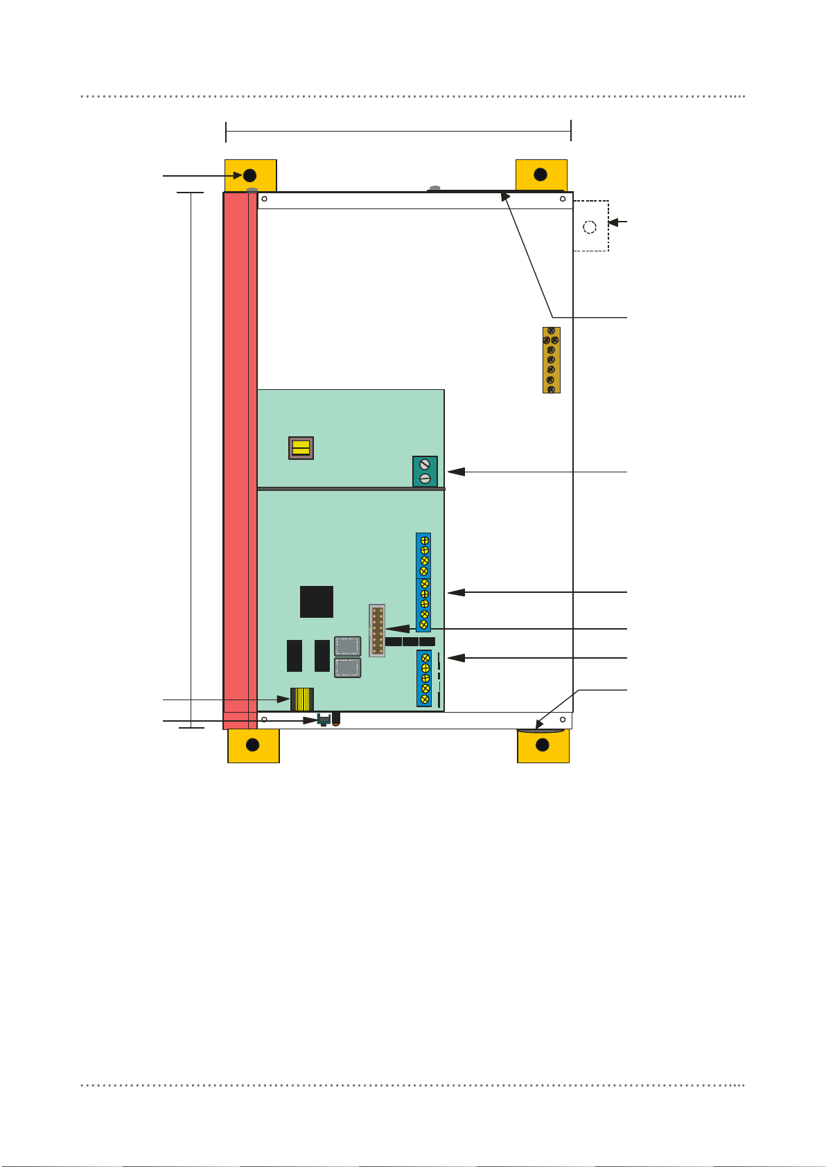
Single Phase Supply
Simple supply requirement, Single
Phase at less than 0.1A.
2 Serial Ports
Both serial ports are RS485.
Optical Isolation
The two halves of the Bridge are linked
by an optical isolation barrier rated at
3.75KV.
DMX512 Gateway Mode
This device can be programmed to
convert DMX512 receive, to 64
channels of DyNet.
Internal Sequencer
The DNG485 has powerful sequencing
capability, with Tasks able to be started
from dry contact closures, Start Task
messages, and from any section of a
normal network messages, with
wildcards available for any byte of the
packet. User accessible Ram, and
conditional branching are available to
the programmer. Programming of the
sequencer is via DLight™ PC software.
Contact your local agent for details.
important safeguards
Warning –This is a class A product. In a
domestic environment this product may cause
radio interference, in which case the user may
be required to take adequate measures.
Read Instructions –We recommend that you
read this Instruction Manual prior to
commencement of installation. Retain
instructions and give to the end user.
Troubleshooting - If problems are
encountered, read the troubleshooting section
on page 7.
Special Programming –This device will only
operate in basic modes unless programmed
via a computer. If programming is required,
contact your local agent for details. You
should have all terminations made and be able
to turn all lighting circuits on and off from
control plates before the programming
engineer arrives at the job.
Check Connections –Treat this device as a
switchboard that has been shipped. Tighten all
screw connections, as vibrations from transport
can cause MCB and terminal block screws to
become loose.
Power Sources –This device should only be
operated from the type of supply specified on
the front panel. This device must be earthed.
Data Cable –The recommended cable for
connections to the serial port is screened,
stranded RS485 data cable with three twisted
pairs. Part numbers for various manufacturers
are listed on page 6. This cable should be
segregated from mains cables by a minimum
distance of 300mm. If anticipated cable runs
are over 600 metres for serial cables, consult
your dealer for advice. Do not cut or terminate
live data cables.
Megger Testing –Do not megger test any
circuitry connected to the control system, as
damage to the electronics may result.
Mounting Location –This device should be
mounted with a minimum clearance of 100mm
for all sides, to enable access to the service
switches and LEDs. Install in a dry, well-
ventilated location. (Refer to page 5 for
mounting instructions.)
Warning
TO REDUCE THE RISK OF FIRE OR
ELECTRIC SHOCK, DO NOT EXPOSE
THIS DEVICE TO RAIN OR MOISTURE.
DO NOT ENERGISE UNLESS THE
FRONT COVER IS IN PLACE.
THIS DEVICE MUST BE EARTHED.
INSTALLATION, PROGRAMMING AND
MAINTENANCE MUST BE CARRIED
OUT BY QUALIFIED PERSONNEL.