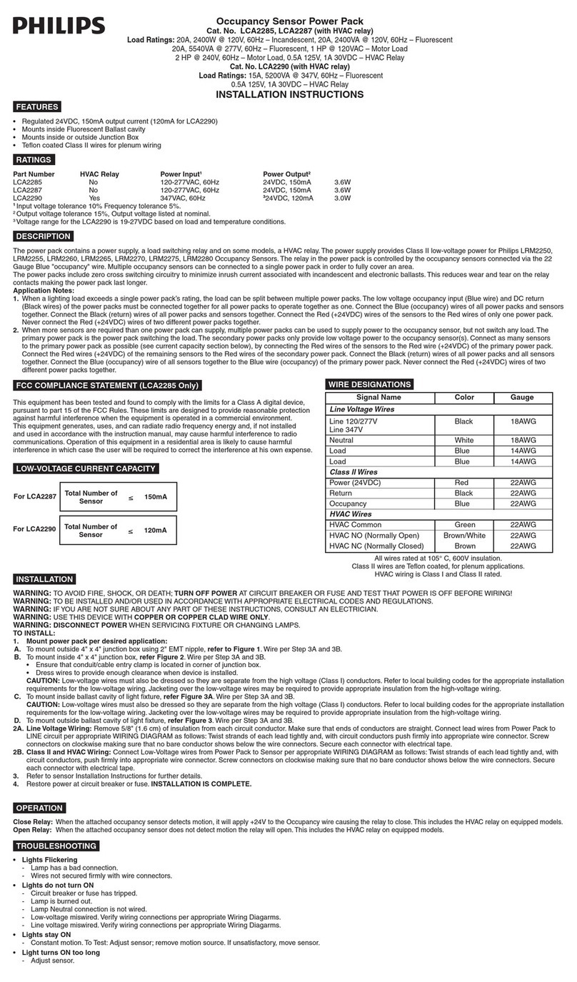
Occupancy Sensor AutoON/Override Power Pack
Cat. No. LCA2292
Load Ratings: 20A, 2400W @ 120V, 60Hz - Incandescent / 20A, 2400VA @ 120V, 60Hz - Fluorescent
20A, 5540VA @ 277V, 60Hz - Fluorescent / 1/2 HP @ 120V - Motor Load / 2 HP @ 240/277V, 60Hz - Motor Load / 0.5A 120V, 1A 30VDC - HVAC Relay
For use with LRM2250, LRM2255, LRM2260, LRM2265, LRM2270,LRM2275, LRM2280 Low Voltage Sensors
INSTALLATION INSTRUCTIONS
WARNINGS AND CAUTIONS:
• TO AVOID FIRE, SHOCK, OR DEATH; TURN OFF POWER at circuit breaker or fuse and test that power is off before wiring!
• Tobeinstalledand/orusedinaccordancewithappropriateelectricalcodesandregulations.
• Ifyouareunsureaboutanypartoftheseinstructions,consultanelectrician.
• Usethisdevicewithcopper or copper clad wire only.
• Disconnect powerwhenservicingxtureorchanginglamps.
• LightsFlickering
- Lamphasabadconnection.
- Wiresnotsecuredrmlywithwireconnectors.
• LightsdidnotturnON
- Circuit breaker or fuse has tripped.
- Lampisburnedout.
- LampNeutralconnectionisnotwired.
- HoldOFForManualONinputisactive.
- LowVoltagemisswired.Verifywiringpreappropriatediagram.
- LineVoltagemisswired.Verifywiringpreappropriatediagram.
• LightsstayON
- Constantmotion.To Test:adjustsensor;removemotionsource(HVAC,Mask,or
movesensor).
• LightsturnONtoolong
- Adjust sensor settings.
• LightscameONduringpresentation
- AutoONmodeisconnectedandthetimedelayexpired.
- Increasethesensortimedelayorgeneratemoremotionduringthepresentation.
• LightsdonotturnOFFwithtimedelay
- HoldONinputisactive.
FEATURES
• Title24Compliant
• HoldOn/HoldOffcapabilities
• Regulated24VDC,150mAoutputcurrent
• MountsinsideFluorescentBallastcavity
• MountsinsideoroutsideJunctionBox
• RatedforPlenumspaces
RATINGS
PartNumber HVAC Relay Power Input1Power Output2
LCA2292 Yes 120-277VAC,50/60Hz 24VDC,150mA3.6W
1Inputvoltagetolerance10%,Frequencytolerance5%.
2Outputvoltagetolerance15%,Outputvoltagelistedatnominal.
DESCRIPTION
Thepowerpackcontainsapowersupply,aloadswitchingrelayandanHVACrelay.
ThepowersupplyprovidesClass2low-voltagepowerforLRM2250,LRM2255,
LRM2260, LRM 2265, LRM2270, LRM2275, and LRM2280 Series Occupancy
Sensors.Therelayinthepowerpackiscontrolledbytheoccupancysensors
connectedviathe22GaugeBlue"occupancy"wire.Multipleoccupancysensors
canbeconnectedtoasinglepowerpackinordertofullycoveranarea.Thepower
packsincludezerocrossswitchingcircuitrytominimizeinrushcurrentassociatedwith
incandescentandelectronicballasts.Thisreduceswearandtearontherelaycontacts
makingthepowerpacklastlonger.
Application Notes:
1. Whenalightingloadexceedsasinglepowerpack’srating,theloadcanbesplit
betweenmultiplepowerpacks.Thelowvoltageoccupancyinput(Bluewire)andDC
return(Blackwires)ofthepowerpacksmustbeconnectedtogetherforallpower
packstooperatetogetherasone.ConnecttheBlue(occupancy)wiresofallpower
packsandsensorstogether.ConnecttheBlack(return)wiresofallpowerpacksand
sensorstogether.ConnecttheRed(+24VDC)wiresofthesensorstotheRedwires
ofonlyonepowerpack.NeverconnecttheRed(+24VDC)wiresoftwodifferent
power packs together.
2. Whenmoresensorsarerequiredthanonepowerpackcansupply,multiplepower
packs can be used to supply power to the occupancy sensor, but not switch any
load.Theprimarypowerpackisthepowerpackswitchingtheload.Thesecondary
powerpacksonlyprovidelowvoltagepowertotheoccupancysensor(s).Connectas
manysensorstotheprimarypowerpackaspossible(seecurrentcapacitysection
below),byconnectingtheRedwiresofthesensorstotheRedwire(+24VDC)of
theprimarypowerpack.ConnecttheRedwires(+24VDC)oftheremainingsensors
totheRedwiresofthesecondarypowerpack.ConnecttheBlack(return)wiresof
allpowerpacksandallsensorstogether.ConnecttheBlue(occupancy)wireofall
sensorstogethertotheBluewire(occupancy)oftheprimarypowerpack.Never
connecttheRed(+24VDC)wiresoftwodifferentpowerpackstogether.
FCC COMPLIANCE STATEMENT (LCA2292)
ThisequipmenthasbeentestedandfoundtocomplywiththelimitsforaClassAdigital
device,pursuanttopart15oftheFCCRules.Theselimitsaredesignedtoprovide
reasonableprotectionagainstharmfulinterferencewhentheequipmentisoperated
inacommercialenvironment.Thisequipmentgenerates,uses,andcanradiateradio
frequencyenergyand,ifnotinstalledandusedinaccordancewiththeinstruction
manual,maycauseharmfulinterferencetoradiocommunications.Operationofthis
equipmentinaresidentialareaislikelytocauseharmfulinterferenceinwhichcasethe
userwillberequiredtocorrecttheinterferenceathisownexpense.
LOW-VOLTAGE CURRENT CAPACITY
INSTALLATION
LCA2292 TotalNumberofSensors ≤150mA
1. WARNING:TOAVOIDFIRE,SHOCK,ORDEATH;TURN OFF POWERAT
CIRCUITBREAKERORFUSEANDTESTTHATPOWERISOFFBEFOREWIRING!
2. Mount power pack per desired application:
A. Tomountoutside4"x4"junctionboxusing2"EMTnipple,refertoFigure 1. Wire
per instructions Step 3A and 3B.
B. Tomountinside4"x4"junctionbox,refertoFigure 2. Wire per instructions Step
3A and 3B.
•Ensurethatconduit/cableentryclampislocatedincornerofjunctionbox.
•Dresswirestoprovideenoughclearancewhendeviceisinstalled.
CAUTION:Low-voltagewiresmustalsobedressedsotheyareseparate
fromthehighvoltage(ClassI)conductors.Refertolocalbuildingcodesforthe
appropriateinstallationrequirementsforthelowvoltagewiring.Jacketingoverthe
low-voltagewiresmayberequiredtoprovideappropriateinsulationfromthehigh-
voltagewiring.
C. Tomountinsideballastcavityoflightxture,refertoFigure 3A. Wire per
instructions Step 3A and 3B.
CAUTION:Low-voltagewiresmustalsobedressedsotheyareseparate
fromthehighvoltage(ClassI)conductors.Refertolocalbuildingcodesforthe
appropriateinstallationrequirementsforthelowvoltagewiring.Jacketingoverthe
low-voltagewiresmayberequiredtoprovideappropriateinsulationfromthehigh-
voltagewiring.
D. Tomountoutsideballastcavityoflightxture,refertoFigure 3B. Wire per
instructions Step 3A and 3B.
3A. Line Voltage Wiring:Remove5/8"(1.6cm)ofinsulationfromeachcircuitconductor.
Makesurethatendsofconductorsarestraight.ConnectleadwiresfromPowerPack
toLINEcircuitperappropriateWIRINGDIAGRAMasfollows:Twiststrandsofeach
leadtightlyand,withcircuitconductorspushrmlyintoappropriatewireconnector.
Screwconnectorsonclockwisemakingsurethatnobareconductorshowsbelowthe
wire connectors. Secure each connector with electrical tape.
3B. Class 2 and HVAC Wiring:ConnectLow-VoltagewiresfromPowerPacktoSensor
perappropriateWIRINGDIAGRAMasfollows:Twiststrandsofeachleadtightlyand,
withcircuitconductors,pushrmlyintoappropriatewireconnector.Screwconnectors
onclockwisemakingsurethatnobareconductorshowsbelowthewireconnectors.
Secure each connector with electrical tape.
4. Refer to sensor Installation Instructions for further details.
5. Restore power at circuit breaker or fuse. INSTALLATION IS COMPLETE.
Mounts outside
junction box
Figure 1
Line Voltage Wires
Class 2 Wires
Figure 2
Mounts inside
junction box
Line Voltage Wires
Class 2 Wires
OPERATION
TheAutoOn/OverridePowerPackcanbeturnedONandOFFautomaticallyusingan
occupancysensorinput,atimer,panelorBASinput,andmanuallyfromanoptionallow
voltagemomentaryswitch.
AUTOON(SeeWiringDiagram):
Theoccupancysensorinput,HoldONinputandtheoptionalmomentaryswitchinputcan
all be used to turn the load ON.
WhentheloadisturnedOFFusingthemomentaryswitch,thepowerpackdoesnotturn
itONautomaticallyuntilafterthesensortimedelayexpires(e.g.,presentationmode).
PressingthemomentaryswitchbeforethesensortimedelayexpiresturnstheloadON.
Whentheoccupancysensor’stimedelayexpires,thepowerpackrevertstoAutoONmode
anditturnstheloadONwiththenextinputfromtheoccupancysensor.
MANUALON(SeeWiringDiagram):
OccupantsmustpressthelowvoltagemomentaryswitchtoturntheloadON.
When the occupancy sensor is the only input keeping the load ON, the load turns OFF
whenthesensortimedelayexpires.Ifthesensorinputre-triggerswithin30secondsafter
theloadturnsOFF,theloadturnsONagain.Afterthe30secondsexpirewithnosensor
inputpressthemomentaryswitchtoturntheloadON.
LOW VOLTAGE INPUTS
24VDCinputwiresareprovidedtocontroltheloadrelay.Theinputsmaybeusedin
combinationorindividually,dependingontheapplication(s).Seewiringdiagramsfor
connections.
MAINTAINED INPUTS
Occupancy Sensor (Blue)-ThisinputisforoccupancysensorAutoON/AutoOFF.
Applying24vclosestherelay(Occupied).Removethevoltageandtherelayopens(Vacant).
Occupancy Sensor (Blue/White)-ThisinputisforoccupancysensorManualON/AutoOFF.
Whentheattachedoccupancysensordetectsmotion,noactionoccurs.Alocal
momentaryswitchisrequiredtomanuallyturntheloadON.Thenthesensorwillturnthe
loadOFFwhenthetimedelayexpires.
Hold ON (Yellow)-Thisinputisintendedfortimerorpanelinput.
Applying24VDCclosestherelay and disables other inputs.
Itcan be overridden by the HoldOFFinput.
Hold OFF (Orange)–Thisinputisusedfortimer,panel,BASorloadshedinput.
Applying24VDCopenstherelay.Removethevoltageandtherelaycanacceptanyother
input.ItoverridestheControlONandHoldONinputs.
Local Switch (Yellow/Orange)–Thisinputisforalowvoltagemomentaryswitch.
Applying24VDCmomentaryinputchangestherelaytotheoppositestate.Itoverridesthe
Control ON, Hold ON and Hold OFF inputs.
• All wires rated at 105o C, 600V insulation.
• Class 2 wires are Te flon coated, for plenum applications.
• HVAC wiring is Class 1 and Class 2 rated.
Line Voltage Wires
Class 2 Wires
Line 120-277V
Neutral
Load
Load
Power (24 VDC)
DC Return
Occupancy Auto ON
HVAC Wires
HVAC Common
HVAC NO (Normally Open)
HVAC NC (Normally Closed)
Occupancy Manual ON
Hold ON
Hold OFF
Local Switch Input
Signal Name
Black
White
Blue
Blue
Red
Black
Blue
Green
Brown/White
Brown
Blue/White
Ye llow
Orange
Ye llow/Orange
Color
18 AWG
18 AWG
14 AWG
14 AWG
22 AWG
22 AWG
22 AWG
22 AWG
22 AWG
22 AWG
22 AWG
22 AWG
22 AWG
22 AWG
Gauge
Wire Designations
TROUBLESHOTING


