Philips MSX VW 0030 User manual

PHILIPS
80 COLUMN LETTER QUALITY
MATRIX PRINTER
VW 0030/20
NewMedia Sol

PT
Fee
EE
4

PHILIPS VWOO30
Letter-quality matrix printer
English 1
Deutsch 9
Francais 19
Nederlands 29
Italiano 39
Espanôl 49

CONTENTS
Control panel and switches
Installing and using your printer …
Installing and removing the ribbon cassette
Paper loading: Single sheets
Fan-fold paper
Adjusting the print head
Test functions:
Printer self-testing
Hexadecimal dump
Margin setting
Dip switch setting
Control codes, summary
Technical specifications zm: ea
Character category specifications
.
Character set tables
Parallel interface specification
Cautionsfor use
Troubleshooting
Appendix A
Appendix B
Appendix C
Appendix D
OONNN—=
Boowasanonnsn

LETTER-QUALITY MATRIX PRINTER
CONTROL PANEL AND SWITCHES ©
A. POWER ON INDICATOR
The green indicator lights up when the powerof the printer is switched on
B. PAPER OUT INDICATOR
The red indicator lights up and an audible signal sounds whentheprinter detects that no paper has
been inserted. The printer automatically enters the OFF-LINE state. To continue insert paper and press
the ON-LINE key.
C. ON-LINE KEY AND INDICATOR
eWhen the green indicator lights up the printer is in the ON-LINE state.
©Press the ON-LINE button and theprinter is in the OFF-LINE state.
©Press again to put printer in ON-LINE state again.
D. L.Q. KEY AND INDICATOR (Letter Quality)
(Can be activated only in the OFF-LINE state.)
e When the green indicator lights up the printer is in letter quality mode.
©Press the LQ-button for standard mode.
©Press again for letter quality mode.
E. RF KEY (Form Feed)
(Can be activated only in the OFF-LINE state.) When using single sheets, asheetis automatically moved
to the end of the page when you press the FF-button.
(The red PAPER OUT indicator will light up.)
FL.E KEY (Line Feed)
(Can be activated only in the OFF-LINE state.) Every time this key is pressed the paper is transported one
line. If you keep the L.F. key depressed the paper will continue to be transported until you release the key
again.
Note: These same keys are used for margin setting, as indicated on the control panel, immediately
underneath the keys. Forfurter details, see chapter ‘Margin Setting’ on page 4.
DIP SWITCHES
The dip switches are located at the back of the machine.
(See page 5for further details.)

INSTALLING AND USING YOUR PRINTER
Make sure that both your computer ©and printer ©are turned off before connecting the printer!
Use the special interface cable © ,provided with your printer, to connectit to the printer interface of your
computerand fasten the locking-clips.
Read theseinstructions carefully and follow them step by step when using your printer for the first time.
Subjects like paper loading and installation of the ribbon cassette are particularly important. The same
applies to the chapters on cautions for use and troubleshooting.
When writing your own programs in MSX-BASIC, including the use of aprinter, the following statements
apply:
PRINT To print or write data into afile.
LPRINT To print data on paper via the printer.
LLIST To print aprogram or part of aprogram on paper.
OPEN To open
a
file and allocate abuffer.
CLOSE To close
a
file and release the associated memory buffer.
SCREEN To declare a printer MSX or non-MSX.
LPOS Gives an indication of the print position in abuffer.
See your MSX-BASIC manuals for further details.
INSTALLING AND REMOVING THE RIBBON
CASSETTE ©
Note: You will find aribbon cassette packed with your printer. Additional cassettes are available through
your dealer. (Type number SBC 436.)
Installation
Make sure that your printer is turned off first.
Remove theprinter cover ©.
Move the print head © to the home position (to the extreme left).
Tum the ribbon feed knob
®
in the direction of the arrow to remove possible slack from the ribbon.
Insert the ribbon between the ribbon mask ©(1) and the print head ©(2) and position the cassette so
that the feed shaft ®is inserted into the hole under theribbon feed knob.
Press both ends of the cassette down firmly.
g. Tighten the ribbon by turning the ribbon feed knob in the direction of the arrow and make sure the ribbon
is still properly positioned in frontof the print head.
h. Close the printer cover again.
geoon
Removal
Firmly hold the fin on top of the cassette ©and pullit straight up.
PAPER LOADING
Single sheets
a. Mount paper shelf ®by first placing it onto the special supports on the printerin upright position.
b. Tilt up the papershelf. Fold out the support @behind the paper shelf and placeits end into the notchin
the printer.
c. Setthe left paper guide ®@ into the proper position for your left margin:
eSlide the paper guide up (in the direction of the arrow) to release it.
©Put it in the proper position and slide it down again until it locks.

Setthe right paper guide ®simply by sliding it to the left or the right, as required.
Put the power switch ©on. The green POWER ON indicatorwill light up.
Place asheet of paper on the papershelf, between the paper guides.
Pull the paper loading handle ® towards you and the paper will automatically be transported to the
properstarting position. (The printing will then start 1inch from the top of the sheet.)
Push the loading handle to the rear again and the paper bail ®will set.
Press the ON-LINE key and your printer is ready for action.
">
oroe
Notes
1. Ifyou want to shift asheet of paper afterit has been loaded, you caneasily do so after completing the
loading process as described above, since the paper is only held loosely by the friction mechanism.
Make sure that the paper remains straightin the printer.
2. Ifthe left-hand paper guide has been set to its leftmost position, the left-hand margin of the printed
sheet will be approx. 1inch.
3. The two rollers of the paper bail should never be set to the outer edges of the paper but approx. one
third ofthe width from the edges ®.
Mounting the tractor unit © and inserting fan-fold paper.
a. See to it that the poweris tumed off.
b. Remove the printer cover and the paper shelf.
c. Pull the paper loading handle ®towards you.
Now you can install the paper feed tractor onto the platen:
d. Insert the hooks on either side of the tractor unit into the openings at the front, on either side of the
platen-unit ®.
Push the rearof the tractor unit down so the spring loaded hooks @click into position.
Open both tractor covers @.
Insert the paper into the printer loosely, as far as it will go ®.
Tum your printer on.
First push the paper loading handle to the rear, then pull it forward again and the paper will be
transported automatically until it appears above the print head.
j. Leave the paper loading handle in its front position! Tum the paper knob clockwise to transport the
paper another 10 cm (4 inches).
k. Then move the paper loading handle to its rear position.
|Adjust the tractors to correspond exactiy with the width of the paper you are using.
m. Carefully lay the paper overthe tractors so the pins engage into the sprockets of the paper ®. Then
close the tractor covers again.
n. Now mount the paper shelf again and putit in horizontal position @. (Fold the support flat against the
paper shelf.)
0. Put the printer cover back onto the printer.
p. Now transport the paper by turming the paper feed knob clockwise until the perforation of the second
sheet appears above the print head.
q. Finally press the ON-LINE key and yourprinteris ready for action.
"zorg
Note: Make sure that your printeris set to the proper paper length! (See DIP-switch setting, page 5.)
ADJUSTING THE PRINT HEAD ®
The print head can be adjusted with the print head adjustmentlever. You will find it inside the printer on the
right-hand side.
When shipped from the factory, the leveris set at to a position meant forstraight printing without copy.If you
want to print one or more copies, you can increase the force by moving the lever ® towards you.
Whenprinting single copies it is recommended to reset the leverto its original position to avoid unnecessary
wear and tear on your printer.

TEST FUNCTIONS
Printer self-testing
The printer self-testing facility offers you the opportunity to check the main functions of the printer. There are
two possibilities:
1. Testing Letter Quality printing
©First insert asheet of paper into the printer.
©Then tum the printer off.
eTum the printer on again while you press the L.Q.-key.
Keep the L.Q.-key depressed until the printerstarts its self-test in Letter Quality.
©You can stop the printing by switching the printer off again.
2. Testing Draft Quality printing.
Follow the same procedure as described above. The only difference being that you press the L.F-key
instead of the L.Q.-key.
Hexadecimal dump
The hexadecimal dump facility is meant only to trace possible errors in your MSX-BASIC programs by
providing ahexadecimal print-out of your work.
eFirst tum the printer off.
eTum it on again while keeping the FF-key depressed.
e Then use your MSX commands for aprint-out.
MARGIN SETTING ©
The printer offers the possibility to set both aleft-hand and right-hand margin.
You should not useit when working with aword processing program with margin setting included.
Setting the margins
The control panel of yourprinterindicates which keys to use to set the margins.
©The printer should be in the ON-LINE state first.
©Then press the MARGIN key (=ON-LINE key) and keep it depressed until the green indicator starts
blinking.
©Press the —key(=L.F-key) on the control panel to move the print head to the required position for the left
margin.
(You can use the <key (=FF-key) to move the print head to the left.)
©Then press the SET key .Q.-key) to set the margin.
©Next press the —key again to move the print head to the position where you want the right-hand margin.
eThen press the SET key (= L.Q.-key) again. Now both margins are set. Theprinter automatically returns
to the ON-LINE state (the indicator stops blinking) and the normal function of the keysis restored.
Note:
When you switch the printeroff, the margin setting is lost.

DIP SWITCH SETTING
The following functions can be selected by using the dip switches, located at the backof the printer @. The
dip switches are read after an initialisation process. This is done either by putting the power switch on or by
an ESC,@ command.
Page setting
SWITCH NO. FUNCTION
12
OFF OFF Page lengthis set to 12 inches.
OFF ON Page lengthis set to 8 inches.
ON OFF Page length is set to 11 inches.
ON ON Page length is set to 14 inches.
Italic character setting
Switch 3ON Italic characters.
Switch 3 OFF Standard characters.
Character mode setting
SWITCH NO. FUNCTION
45
OFF OFF Pica mode (10 cpi)
OFF ON Elite mode (12 cpi)
ON OFF Condensed mode (17 cpi)
ON ON Proportional mode
<30>H code selection
Switch 6 ON "0
Switch 6 OFF "0"
1inch perforation skip
Switch 8ON Designated.
Switch 8OFF Not designated.
Note:
Switch 7has no function.
CONTROL CODES
Summary
Notes: Some ofthe functions have priority over others, which means thatthere are limitatons to the
combinations that can be made. When afunction, overriding another function, is cancelled the remaining
function becomes valid again. No error warnings are given.
Print mode priorities are:
eSuper/Subscript >Letter Quality >Double strike.
eCondensed >Letter Quality.
#Condensed >Bold print.
When the Super/Subscript and theitalic functions are continuously designated, the latter input function is
given priority. When one function is terminated the other becomes valid.
For examples see Appendix A.

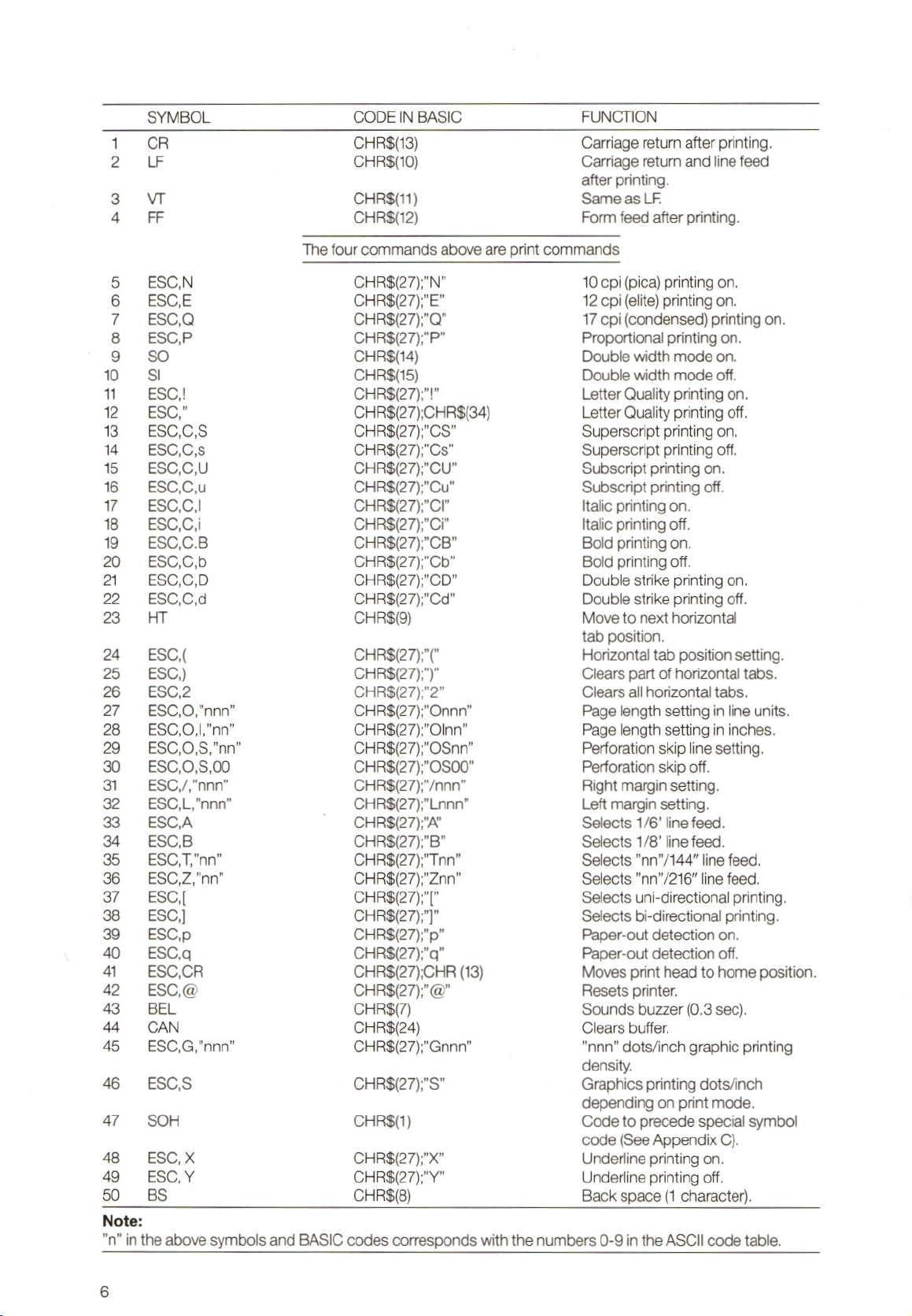
SYMBOL CODE IN BASIC FUNCTION
1CR CHRS$(13) Carriage return after printing.
2LF CHRS(10) Carriage return and line feed
after printing.
3VT CHRS(11) Same as LF.
4FF CHRS(12) Form feed after printing.
Thefour commands above are print commands
5 ESC‚N CHR$(27);N" 10 opi (pica) printing on.
6ESCE CHR$(27);"E" 12 cpi (elite) printing on.
7ESCQ CHRS{(27);"Q" 17 cpi (condensed)printing on.
8ESCP CHR$(27);"P" Proportional printing on.
9SO CHRS$(14) Double width mode on.
10 Sl CHRS$(15) Double width mode off.
11 ESC! CHRS(27);"!" Letter Quality printing on.
12 ESC” CHRS$(27);CHR$(34) Letter Quality printing off.
13 ESC,C,S CHR8(27);"CS" Superscript printing on.
14 ESC,C,s CHR8(27);"Cs" Superscript printing off.
15 ESCCU CHR$(27);"CU" Subscript printing on.
18 ESC,Cu CHR$(27);"Cu" Subscript printing off.
177 ESC,C,! CHR$(27);"CI" Italic printing on.
18 ESCCi CHRS(27);"Ci" Italic printing off.
19 ESC,C.B CHRS(27);"CB" Bold printing on.
20 ESC,C‚b CHR8(27);"Cb" Bold printing off.
21 ESC,C,D CHR$(27);"CD" Double strike printing on.
22 ESC,C,d CHR$(27);"Cd" Double strike printing off.
23 HT CHR$(9) Move to next horizontal
tab position.
24 ESC CHR$(27);"(" Horizontal tab position setting.
25 ESC) CHR$(27);")" Clears part of horizontal tabs.
26 ESC,2 CHR$(27);"2" Clears all horizontal tabs.
27 ESC,0,"nnn” CHR$(27);"Onnn" Page length setting in line units.
28 ESC,0,,"nn" CHR8(27);"Olnn" Page length setting in inches.
29 ESC,0,8,’nn" CHR$(27);"OSnn" Perforation skip line setting.
30 ESC,0,S,00 CHRS$(27);"O0S00" Perforation skip off.
31 ESC,/,"nnn" CHR$(27);"/nnn" Right margin setting.
32 ESC,L/’nnn” CHR$(27);"Lnnn" Left margin setting.
33 ESCA CHR$(27);"A" Selects 1/6’ line feed.
34 ESCB CHR$(27);"B” Selects 1/8’ line feed.
35 ESC,T’nn” CHR$(27);"Tnn" Selects "nn”/144" ine feed.
36 ESC,Z;'nn'" CHR$(27);"Znn" Selects "nn”/216" line feed.
37 ESC[ CHR$(27);"[" Selects uni-directional printing.
38 ESC] CHR$(27);"]" Selects bi-directional printing.
39 ESC‚p CHRS$(27);"p" Paper-out detection on.
40 ESC, CHR$(27);"a" Paper-out detection off.
aESC‚,CR CHRS(27);CHR (13) Moves print head to home position.
42 ESC,@ CHR$(27);"@" Resets printer.
43 BEL CHR$(7) Sounds buzzer (0.3 sec).
44 CAN CHR$(24) Clears buffer.
45 ESC,G,"nnn" CHR$(27);"Gnnn" nnn” dots/inch graphic printing
density.
46 ESC,S CHR$(27);"S" Graphics printing dots/inch
depending on print mode.
47 SOH CHRS(1) Code to precede special symbol
code (See Appendix C).
48 ESC,xX CHR$(27);"X" Underline printing on.
49 ESC,Y CHR$(27);Y" Underline printing off.
50 BS CHR$(8) Back space(1 character).
Note:
”n” in the above symbols and BASIC codes corresponds with the numbers 0-9 in the ASCII code table.

TECHNICAL SPECIFICATIONS
Print method
Characters &Symbols
Graphic printing
Print modes:
Standard quality
Letter quality
9-pin impact matrix.
Bi-directional, short line seeking
254 (including graphic symbols).
8categories:
©8dots vertically
©Horizontal density (dots/inch):
60, 72, 80, 90, 120, 138, and 240°.
*Adjoining dots cannot be printed.
Pica (10 cpi)
Elite (12 cpi)
Condensed (17 cpi)
Proportional
Pica (10 cpi)
Elite (12 cpi)
Proportional
Mixing of the above modeswithin a single line is possible.
Printing of the present data is performed prior to mode change.
Additional possibilities
Paper transport
Line feed pitch
Line feed speed
Paper width
Paper weight
Number of copies
Ribbon
Operating temperature
Storage temperature
Power supply
Power consumption
Dimensions (WxHxD)
Weight
Bold
Double strike
Double width
Superscript
Subscript
Italic
Friction feed
(Pin-feed optional)
Minimum 1/216 inch
6.7 lines/second (6 lines/inch)
Minimum width: 4 inches
Maximum width: 10 inches
50to80g/m
Max. original +2copies, using paper with acombined thickness of max.
0.2 mm.
Single colour (black) in cassette. Number of impressions: approx
2,5 million (draft quality)
5°t0 35°C
—30° to +60°C
220/240 VAC (£ 10%)
50 Hz (£ 3%)
During operation: Approx. 30 W
While idling :Approx. 15W
403 x119 x278 mm (without paper shelf)
4.8kg
CHARACTER CATEGORY SPECIFICATIONS
See Appendix B
CHARACTER SET TABLES
See Appendix C

PARALLEL INTERFACE SPECIFICATION
See Appendix D
CAUTIONS FOR USE
Only use apower supply voltage within the specified range.
Do not touch the print head immediately after printing because it can get very hot during operation.
Be careful that you do not twistthe ribbon while installing it.
Wait at least two seconds after turning the poweroff before turning it back on again. If you don't the
initialisation process may not be performed properly.
Avoid direct sunlight, humidity and dust when using the printer.
Do not perform printing when there is no ribbon and paper in your printer.
Never install the tractorunit when you are using friction feed for cut sheet paper.
When using continuous forms, the paper bail must be setto the platten side otherwise the paper may
jam in the printer.
TROUBLESHOOTING
If your printer does not function properly, try and locate the cause, using the following checklist:
1. The printer does not print and the POWER ON indicator does not light up.
There may be something wrong with the power supply.
Check the power switch and the power cable connection.
2. The printer does notprint while the POWER ON indicator lights up.
First check whether the ribbon cassette has been installed properly. Try aprinter self-test first. If the
self-test works, check the connecting cable with the printer interface.
If all that seems to be in order there may be something wrong with the computer program or the
computeritself.
3. The printer functions properly but the paper is not feeding through the way it should.
The paper is probably jammed in the printer.
Remove the paper and insert it (or a new sheet) properly.
4, The print is light or smeared.
©The print head adjustment is not correct. If so,setit properly according to the paper you are using.
©Therribbon cassette has not been installed properly.
©The ink ribbon is old and worn out.
Replace the ribbon with a new one.
(Type number SBC 436)
You can use the printer self-test facility to check the quality of the ink ribbon.
5. The PAPER OUT indicator blinks.
An error condition has been detected. Turn the poweroff and then back on again.

PHILIPS VW 0030
LETTER-QUALITY MATRIXDRUCKER
INHALT
Bedienungsfeld und Schalter
Installation und Gebrauch des Druckers
Einsetzen und Entnahme der Farbbandkassette ……
Laden des Papiers: Einzelblätter
Endlospapier
Justieren des Druckkopfes
Testfunktionen:
Drucker-Eigentest
Sedezimaler Speicherausdruck
Schreibrandeinstellung
Papierlängeneinstellung (dip switch setting)
Steuercodes, Zusammenfassung
Technische Spezifikation
Spezifikation des Zeichensatzes
Zeichensatz-Tabellen
Spezifikation Parallelschnittstelle
Betriebshinweise
Fehlersuche
Anhang A
Anhang B
Anhang C
Anhang D
10
11
11
11
12
13
13
13
13
14
14
16
17
17
17
17
18
60
73
74
75

LETTER-QUALITY MATRXDRUCKER
BEDIENUNGSFELD UND SCHAUER©
A. ANZEIGE „NETZSPANNUNG EIN”
Die grüne LED-Anzeige leuchtet auf, wenn der Drucker eingeschaltetist.
B. ANZEIGE „PAPER OUT”
Wenn der Drucker feststellt, dass kein Papier eingelegt worden ist, leuchtet die rote LED-Anzeige, und
gleichzeitig ertönt ein akustisches Signal. Der Drucker geht dann automatisch in den Zustand OFF-LINE
über. Zur Fortsetzung des Betriebes Papier laden und ON-LINE drücken.
C. ON-LINE-TASTE UND ANZEIGE
eWenn die grüne LED-Anzeige leuchtet, befindet sich der Drucker im ON-LINE-Zustand.
eON-LINE-Taste drücken: Drucker gehtin den OFF-LINE-Zustand über.
©Taste nochmals drücken: Drucker kehrt wieder in den ON-LINE-Zustand zurück.
D. LQ (LETTER QUALITY)-TASTE UND INDIKATOR
(Aktivierung nur im OFF-LINE-Zustand möglich.)
eWenn die grüne LED-Anzeige leuchtet, arbeitet der Druckerin der Betriebsart „Letter Quality”.
©Zum Übergang auf Normalbetrieb LQ-Taste drücken.
eFür „Letter Quality”-Betrieb Taste nochmals drücken.
E. FF-TASTE (Form Feed =Papiervorschub)
(Aktivierung nur im OFF-LINE-Zustand möglich.)
Wird diese Taste bei Verwendung von Einzelblatt-Papier gedrückt, so erfolgt ein automatischer Transport
bis zum Blattende (rote Anzeige PAPER OUT leuchtet auf.)
FLF-TASTE (Line Feed =Zeilenvorschub)
(Aktivierung nur im OFF-LINE-Zustand möglich.)
Beim Drücken dieser Taste wird das Papier jeweils um eine Zeile weitertransportiert. Wenn Sie die
LF-Taste ständig gedrückt halten, wird das Paper solange transportiert, bis Sie die Taste wieder
freigeben.
Anmerkung: Die gleichen Tasten werden für die Schreibrandeinstellung verwendet, wie auf dem
Bedienungsfeld unmittelbar unter den Tasten angegeben. Weitere Einzelheiten siehe unter
„Schreibrandeinstellung”auf Seite 13.
PAPIERLÄNGENEINSTELLUNG MIT DIP-SCHALTERN
Die DIP-Schalter dienen zur Papierlängeneinstellung und befinden sich an der Rückseite der Konsole.
(Weitere Einzelheiten siehe Seite 14.)
10

INSTALLATION UND GEBRAUCH IHRES DRUCKERS
Überzeugen Sie sich davon, dass sowohl Ihr Computer ®als auch Ihr Drucker ©vor dem
Anschluss des Druckers ausgeschaltet sind!
Schliessen Sie das zu Ihrem Druker mitgelieferte Spezial-Schnittstellenkabel ©an die Drucker-Schrnittstelle
Ihres Computers an und befestigen Sie die Arretierungsclips.
Lesen Sie die nachstehenden Anweisungen sorgfältig durch und befolgen Sie diese Punkt für Punkt beim
erstmaligen Gebrauch Ihres Druckers.
Themen wie „Laden des Papiers” und „Einsetzen der Farbbandkassette” sind besonders wichtig. Das
gleiche gilt für die Kapitel „Betriebshinweise” und „Fehlersuche”.
Für das Schreiben Ihrer eigenen Programme in MSX-BASIC unter Einbeziehung des Druckbetriebs, gelten
folgende Statements:
PRINT Zum Ausdrucken oder Einschreiben von Daten in eine Datei.
LPRINT Zum Ausdrucken von Daten auf Papier Über den Drucker.
LLIST Zum Ausdrucken eines Programms oder Programmteils auf Papier,
OPEN Zur Eröffnung einer Datei und Zuweisung eines Puffers.
CLOSE Zum Abschliessen einer Datei und Freigabe des betreffenden Pufferspeichers.
SCREEN Zum Erklären eines Druckers als MSX oder Nicht-MSX.
LPOS Zur Anzeige der Druckposition in einem Speicher.
Weitere Einzelheiten finden Sie in Inren MSX-BASIC-Handbüchem.
EINSETZEN UND ENTNAHME DER
FARBBANDKASSETTE ©
Anmerkung:
Inrem Druckerliegt eine Farbbandkassette bei. Ersatzkassetten beziehen Sie von Ihrem Händler (Typennr.
SBC 436).
INSTALLATION
Überzeugen Sie sich davon, dass Ihr Drucker ausgeschaltet ist.
Haube (Abdeckung) des Druckers abnehmen ©.
Druckkopf ©in die Endlage bringen (d.h. ganz nach links).
Zum Spannen des Farbbandes den Bandtransportknopf ©in Pfeilrichtung drehen.
Farbband zwischen Bandmaske ©(1) und Druckknopf
©
(2) einsetzen und Kassette so positionieren,
dass die Transportwelle ®in die Bohrung unter dem Bandtransportknopf eingreift.
f. Kassette an beiden Seiten fest nach unten drücken.
g. Farbband durch Drehen des Bandtransportknopfes in Pfeilrichtung spannen, und sicherstellen, dass
das Farbband immer noch vor dem Druckkopf positioniert ist.
h. Druckerhaube wieder schliessen.
Entnahme des Farbbandes
Die Rippe an der Oberseite der Kassette ©erfassen und Kassette geradlinig nach oben ziehen.
ooo
LADEN DES PAPIERS
Einzelblätter
a. Papierauflageplatte ®anbringen. Auflageplatte zunächstin Senkrechtlage auf die entsprechenden
Haltenocken des Druckers setzen.
b. Papierauflageplatte anheben. Stütze ® hinter der Papierauflage herausklappen und ihr Ende in den
Schlitz im Drucker einsetzen.
11

c. Linke Papierführung ®auf den von Ihnen gewünschten Rand instellen:
Papierführung zwecks Freigabe nach oben klappen (in Pfeilrichtung).
Dann Papierführung in die gewünschte Position bringen und bis zum Einrasten wieder herunterklappen.
Rechte Papierführung ®einfach nachlinks oder rechts an die gewünschte Stelle schieben.
Drucker mit Netzschalter ® einschalten. Die grüne LED „NETZSPANNUNG EIN” leuchtet auf.
Ein Blatt Papier zwischen die Papierführungen auf die Papierauflage legen.
Dann den Ladehebel ®auf sich zuziehen: Papier wird automatisch in die richtige Startposition
transportiert. (Das Bedrucken des Papiers beginnt dann im Abstand von 1” vom oberen Rand.)
Ladehebel wieder nach hinten drücken. Damit ist der Papierstapel ©richtig justiert.
ON-LINE-Taste drücken, und Ihr Druckerist betriebsbereit.
"73
orga
Anmerkungen
1. Falls Sie ein Blatt Papier nach dem Laden verschieben möchten, so kann dies auf einfache Weise nach
Beendigung des oben beschriebenen Ladevorgangs geschehen, da das Papier nur lose von der
Zugwalze (friction mechanism) gehalten wird.
Achten Sie darauf, dass das Papier glatt im Drucker bleibt.
2. Wenn die linke Papierführung ganz nach links gestellt ist, ergibt sich links auf dem bedruckten Blatt ein
etwa1” breiter Rand.
3. Die beiden Papierstapel-Andruckrollen sollten niemals an die Aussenkante des Papiers gesetzt werden,
sondern jeweils um 1/3 der Blattbreite von den Kanten entfernt ®.
Montage der Stiftwalzeneinheit ©und einsetzen des Endlospapiers
a. Uberzeugen Sie sich davon, dass der Drucker ausgeschaltet ist.
b. Druckerhaube und Papierauflageplatte abnehmen.
c. Papierladehebel ®auf sich zuziehen.
Jetzt lässt sich die Stiftwalzeneinheit wie folgt auf der Druckwalze anbringen:
d. Die Haken zu beiden Seiten der Stiftwalzeneinheit in die Öffnungen rechts und links an der Vorderseite
der Druckwalzeneinheit ® einsetzen.
e. Rückseite der Stiftwalzeneinheit nach unten drücken, bis die federbelasteten Haken ® einrasten.
f. Beide Stiftwalzenabdeckungen ®öffnen.
g. Papier bis zum Anschlag lose in den Drucker einsetzen @.
h. Drucker einschalten.
iErst den Papierladehebel nach hinten drücken und dann wieder nach vorne ziehen: Das Papier wird nun
automatisch transportiert, bis es Über dem Druckkopf erscheint.
j. Papierladehebele in der vorderen Stellung belassen! Papier durch Drehen des Papiertransportknopfes
im Uhrzeigersinn um weitere 10 cm transportieren.
k. Papierladehebel in die hintere Stellung bringen.
|. Stiftwalzen so einstellen, dass sie genau derBreite des benutzten Papiers entsprechen.
m. Papier sorgfältig Über die Stiftwalzen legen, so dass die Stifte in die Perforation des Papiers ®
eingreifen. Dann Stiftwalzenabdeckung schliessen.
n. Papierauflage montieren und in Horizontalstellung ®bringen, nachdem Sie den Fuss an der Rückseite
erst flach gegen die Auflage gedrückt haben.
0. Druckerhaube wieder auf dem Drucker anbringen.
p. Papier durch Dehen des Papiertransportknopfs im Uhrzeigersinne soweit transportieren, bis die
Perforation des zweiten Blattes über dem Druckknopf erscheint.
q. ON-LINE-Taste drücken, und Ihr Druckerist betriebsbereit!
Anmerkung:
Überzeugen Sie sich davon, dass Ihr Druckerauf die richtige Papierlänge eingestellt ist!
(Siehe Papierlängeneinstellung mit DIP-Schalter, Seite 14.)
12

JUSTIEREN DES DRUCKKOPFES ®
Der Druckkopf kann mit dem Druckkopfjustierhebel eingestellt werden.
Dieser Hebel sitzt rechts im Inneren des Druckers.
In der Fabrik wird der Hebeljustiert. Diese Stellung ist im Prinzip für normale Schreibarbeiten ohne
Durchschläge geeignet. Wünschen Sie einen oder mehrere Duchschläge, so können Sie die Anschlagstärke
durch Nachvornziehen des Hebels ®vergrössem.
Schreiben Sie ohne Durchschlag, so empfiehlt es sich, den Hebel wiederin seine ursprüngliche Stellung zu
bringen, um unnötigen Verschleiss zu vermeiden.
TESTFUNKTIONEN
Drucker-Eigentest
Die Eigentestmöglichkeit gestattet Ihnen die Kontrolle der Hauptfunktionen des Druckers. Zwei
Möglichkeiten stehen zur Verfügung:
1. Testen des „Letter Quality”-Betriebs
©Erst ein Blatt Papierin den Drucker einlegen.
©Dann Drucker ausschalten.
eDrucker wieder einschalten und dabei LQ-Taste drücken.
Taste niedergedrückt halten, bis der Drucker den Eigentest in bezug auf „Letter Quality” startet.
eStoppen des Druckvorgangs durch Ausschalten des Druckers.
2. Testen des „Draft Quality”-Betriebs
Hierzu verfahren Sie in gleicher Weise wie oben. Dereinzige Unterschied besteht darin, dass Sie anstelle
der LQ-Taste nun die LF-Taste drücken.
Sedezimales Ausdrucken
Die Sedezimal-Ausdruckmöglichkeit ist vorgesehen, um etwaige Fehler Ihres MSX-BASIC-Programms
aufzuspüren.
©Erst den Drucker ausschalten.
e Drucker wieder einschalten und dabei FF-Taste gedrückt halten.
©Dann Ihre MSX-Befehle für das Ausdrucken eingeben.
SCHREIBRANDEINSTELLUNG ©
Der Drucker gestattet die Einstellung eines linken wie auch eines rechten Schreibrandes.
Diese Möglichkeit entfällt, wenn Sie mit einem Textverarbeitungsprogramm einschi. Schreibrandeinstellung
arbeiten.
Einstellung der Schreibränder
Das Bedienungsfeld Ihres Druckers zeigt an, welche Tasten zur Schreibrandeinstellung dienen.
e Erst den Druckerin den ON-LINE-Zustand bringen.
eDann die Schreibrandtaste (=ON-LINE-Taste) drücken und solange gedrückt halten, bis die grüne
LED-Anzeige blinkt.
eTaste ‚—” (= LF-Taste) des Bedienungsfeldes drücken, um den Druckkopf in die gewünschte Position für
den linken Rand zu bringen. (Linksbewegung des Druckkopfes durch Drücken derTaste „—” (=FF-Taste).
eDann Taste SET (=LQ-Taste) zur Randeinstellung drücken.
eTaste „—" abermals drücken, um den Druckkopf am rechten Rand zu positionieren.
eDann nochmals Taste SET (=LQ-Taste) drücken. Damit sind beide Schreibränder eingestellt. Der
Drucker kehrt automatisch in den ON-LINE-Zustand zurück (Anzeige blinkt nicht mehr), und die normale
Tastenfunktion ist wiederhergestellt.
Anmerkung: Beim Ausschalten des Druckers geht die Schreibrandeinstelilung verloren.
13

PAPIERLÄNGENEINSTELLUNG MIT DIP-SCHALTERN
Die folgenden Funktionen sind mit den DIP-Schaltern an der Rückseite des Druckers ®wählbar. Die
DIP-Schalter werden nach einem Initialisierungsprozess ausgelesen. Dies geschieht entweder durch
Einschalten des Druckers oder durch einen ESC, @-Befehl.
Seiteneinstellung
SCHALTER NR. FUNKTION
12
AUS AUS Einstellung der Seitenlänge auf 12".
AUS EIN Einstellung der Seitenlänge auf 8”.
EIN AUS Einstellung der Seitenlänge auf 11”
EIN EIN Einstellung der Seitenlänge auf 14"
Einstellung von Kursivschrift
Schalter 3EIN Kursivschrift.
Schalter 3 AUS Normalschrift.
Einstellung der Schriftart
SCHALTERNR. FUNKTION
45
AUS AUS Pica (Schreibschritt 1/10")
AUS EIN Elite (Schreibschritt 1/12")
EIN AUS Condensed (Schreibschritt 1/17")
EIN EIN Proportionalschrift
<30> HCode-Selektion
Schalter 6EIN "0
Schalter 6AUS ei
1-Perforationssprung
Schalter 8EIN =zugewiesen
Schalter 8AUS =nicht zugewiesen
Anmerkung:
Schalter 7hat keine Funktion.
STEUERCODES
Zusammenfassung
Anmerkung: Einige der Funktionen geniessen Priorität gegenüber anderen. Dies bedeutet, dass die
möglichen Kombinationen Beschränkungen unterliegen. Wird eine Funktion, die eine andere aufgehoben
hat, gelöscht, so wird die ursprüngliche Funktion wiederhergestelit. Es erfolgen keine Fehlermeldungen.
Die Druckmodi-Prioritäten sind wie folgt:
eSuper/Subscript >Letter Quality >Doppelanschlag.
eCondensed >Letter Quality.
©Condensed >Fettdruck.
Wenn Super/Subscript (=Hochsetzen/Indizieren) und Kursiv ständig zugewiesen werden, geniesst die
letztgenannte Funktion Priorität.
Wird eine Funktion aufgehoben, so wird die andere aktiviert.
Beispiele siehe Anhang A.
14

SYMBOL BASIC-CODE FUNKTION
1CR CHR$(13) Wagenrücklauf nach dem Druck.
2LF CHRS$(10) Wagenrücklauf und Zeilenvorschub
nach dem Druck
3VT CHRS(11) Wie LF
4FF CHRS(12) Papiervorschub nach dem Druck
Die obigen vier befehle sind Druckbefehle.
5ESC‚,N CHRS(27);"N" Schreibschritt 1/10" (Pica)
eingeschaltet.
8ESC CHRS(27)/”E" Schreibschritt 1/12" (Elite)
eingeschaltet.
7ESCQ CHR$(27);"Q" Schreibschritt 1/17" (Condensed)
eingeschaltet.
8ESCP CHR$(27);"P" Proportionaldruck eingeschaltet.
9SO CHR$(14) Doppelte Zeichenbreite
eingeschaltet.
10 SI CHRS$(15) Doppelte Zeichenbreite
ausgeschaltet.
11 ESC! CHR$(27);"!" Letter Quality eingeschaltet.
12 ESC” CHR$(27);CHR$(34) Letter Quality ausgeschaltet.
18 ESC,C,S CHRS(27);"CS" Superscript (Hochsetzen)
eingeschaltet.
14 ESC,C,Ss CHRS(27);"Cs" Superscript (Hochsetzen)
ausgeschaltet.
15 ESCCU CHR$(27);"CU" Subscript (Indizieren) eingeschaltet.
16 ESC,C‚,u CHR$(27);"Cu" Subscript (Indizieren)
ausgeschaltet.
17 ESC,C! CHR$(27);"C" Kursiv eingeschaltet.
18 ESC,C CHR$(27);"Ci" Kursiv ausgeschaftet.
19 ESC,CB CHR$(27);"CB" Fettdruck eingeschaltet.
20 ESC,C‚b CHR$(27);"Cb" Fettdruck ausgeschaltet.
21 ESC,C,D CHRS(27);"CD" Doppelter Anschlag eingeschaltet.
22 ESC,C,d CHR$(27);"Cd" Doppelter Anschlag ausgeschaltet.
23 HT CHR$(9) Positionierung auf nächste
Schreibspalte (hor. Tab.).
24 ESC CHR$(27);"(" Einstellung der Hor.Tab.-Position.
25 ESC) CHRS(27);")" Teillöschung der
Hor..Tab.-Einstellungen.
26 ESC,2 CHRS$(27);"2" Löschung sämtlicher
27 ESC,0,"nnn”
28 ESC,0,,"nn”
29 ESCO,S,/’nn"
30 ESC,0,8,00
31 ESC,/"nnn"
32 ESC,L"nnn”
33 ESC,A
34 ESCB
35 ESC,T,’nn”
36 ESC,Z'nn”
37 ESC[
38 ESC]
39 ESCp
40 ESC,
*Engl.: Perforation skip line setting.
CHRS(27);"Onnn"
CHR$(27);"Olnn"
CHRS(27);"OSnn"
CHRS(27);”O0S00"
CHR$(27);"/nnn"
CHRS(27);"Lnnn"
CHR$(27);"A"
CHR8(27);"B"
CHRS(27);"Tnn"
CHR$(27);"Znn"
CHRS(27);"["
CHRS(27);"|"
CHR$(27);"p"
CHR$(27);"qa"
Hor.Tab.-Einstellungen.
Seitenlängeneinstellung in
Zeileneinheiten.
Seitenlängeneinstellung in Zoll.
Perforationssprung-
linieneinstellung”.
Perforationssprung AUS.
Rechte Schreibrandeinstellung.
Linke Schreibrandeinstellung.
Zeilenvorschubwahl 1/6".
Zeilenvorschubwahl 1/8".
Zeilenvorschubwahl ”nn"/144".
Zeilenvorschubwahl ”nn"/216".
Wahl Ein-Richtungsbetrieb.
Wahl Zwei-Richtungsbetrieb.
Detektion PAPER OUT
eingeschaltet.
Detektion PAPER OUT
ausgeschaltet.
15

aESC,CR CHRS(27);CHR (13) Positionieren des Druckkopfes
in der Endlage.
42 ESC,@ CHR$(27);"@" Rücksetzung des Druckers.
43 BEL CHR$(7) Akustisches Signal (Summer,
0,38).
44 CAN CHR$(24) Löschung des Puffers.
45 ESC,G, "nnn" CHR$(27);"Gnnn” Graphische Schreibdichte ”nnn”
Punkte/Zoll.
46 ESC,S CHR$(27);"S" Graphische Schreibdichte in
Punkten/Zoll in Abhängigkeit von
der Schriftart.
47 SOH CHRS(1) Ein dem speziellen Symbolcode
vorausgehender Code (siehe
Anhang C).
48 ESC,X CHR$(27);"X" Unterstreichung eingeschaltet.
49 ESC,Y CHR$(27);"Y" Unterstreichung ausgeschaltet.
50 BS CHR$(8) Rücksetzschritt (1 Zeichen).
Anmerkung:
”n” in den obigen Symbolen und BASIC-Codes entspricht den Ziffern 0-9 im ASCII-Code.
TECHNISCHE SPEZIFIKATION
Druckverfahren Mechanischer Impact-Drucker mit 9 Nadeln.
Zweirichtungsdruck, kurze Zeilensuchzeit.
Zeichen &Symbole 254 (einsch!. graphischer Symbole).
Graphischer Druck 8 Kategorien:
©8Punkte vertikal
ehorizontale Dichte (Punkte/Zoll):
60, 72, 80, 90, 120, 136 und 240°
*Benachbarte Punkte können nicht gedruckt werden.
Schriftarten:
Standard Quality Pica (Schreibschritt 1/10")
Elite (Schreibschritt 1/12")
Condensed (Schreibschritt 1/17")
Proportional
Letter Quality Pica (Schreibschritt 1/10")
Elite (Schreibschritt 1/12")
Proportional
Mischung der obigen Schríftarten innerhalb einer einzelnen Zeile ist möglich. Das Ausdrucken
voreingesteliter Daten erfolgt vor dem Schriftartwechsel.
Zusätzliche
Möglichkeiten Fettdruck
Doppelter Anschlag
Doppelter Abstand
Superschript (Hochsetzen)
Subscript (Indizieren)
Kursiv
Papiertransport Zugwalze(friction feed)
Wahlweise Stiftwalze (pin feed)
Zeilenvorschub Minimal 1/216”
Zeilenvorschub-
geschwindigkeit 6,7 Zeilen/s (6 Zeilen/Zol\)
Papierbreite Minimum: 4"
Maximum: 10"
Papiergewicht 50-80 9/m
16
This manual suits for next models
1
Table of contents
Languages:
Other Philips Printer manuals

Philips
Philips LaserMFD 6050 WLAN User manual

Philips
Philips CRYSTAL 660 - NETWORK Instruction sheet

Philips
Philips CRYSTAL 650 - NETWORK User manual

Philips
Philips VW0020 User manual

Philips
Philips LaserMFD 6050 WLAN User manual

Philips
Philips Perfection V600 User manual

Philips
Philips MSX NMS 1431/00 User manual

Philips
Philips CSM 66 III User manual

Philips
Philips LaserMFD LFF 6050 User manual

Philips
Philips MF-JET 500 User manual