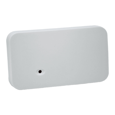
InnoSenT iSYS-4001 User manual

iSYS-4001
quick-start guide V1.1
www.InnoSenT.de
30°
45°
60°
2.2m

iSYS-4001 | quick start guide
www.InnoSenT.de
2www.InnoSenT.de - Experience and Reliability in Radar-Technology
content
• quick start
• configuration settings
• short-range configuration
• detection fields
• long-range configuration
• typicall detection patter for cars
• individual configuration
• iSYS-4001 - detection fields
• depending on mounting height
• depending on mounting angle
• detection distance (RCS)
• ambiguity range
• FSK modulation
• FMCW option
• contact
4
5
6
7
8
9
10
12
13
14
16
18
20
22
25

iSYS-4001 | quick-start guide www.InnoSenT.de
3
Experience and Reliability in Radar-Technology - www.InnoSenT.de
iSYS-4001
quick-start guide
The quick-start guide gives you a guidence to set-up the iSYS-4001 quickly in your application.
A more detailed instruction is given in the GUI - description that is available @ www.innosent.de.

iSYS-4001 | quick start guide
www.InnoSenT.de
4www.InnoSenT.de - Experience and Reliability in Radar-Technology
quick start
Install the iSYS-4001 GUI software as described in the document „GUI Interface“ and connect the sensor to your computer.
If you use the iSYS-4001 the first time InnoSenT recommends to use one of the available configuration files to set up the
sensor.
The DEFAULT setting of the sensor when powered up for the first time is the „Short Range“ configuration.
The following configuration files are available @ www.InnoSenT.de (Services -> Downloads)
• Short Range.ipf (for short range applications up to 50m)
• Long Range.ipf (for long range applications up to 150m)
• Demonstrator.ipf (for testing the sensor in house)
Examples how to mount the sensor and the expected detection fields are given on the next pages.

iSYS-4001 | quick-start guide www.InnoSenT.de
5
Experience and Reliability in Radar-Technology - www.InnoSenT.de
configuration settings
The following settings apply for the different configuration sets:
Short Range.ipf Long Range.ipf Demonstrator ipf
output1 approaching & receding
active low, if object exist
active high, if NO object exist
approaching & receding
active low, if object exist
active high, if NO object exist
approaching & receding
active low, if object exist
active high, if NO object exist
output 2 approaching
active high, if object exist
active low, if NO object exist
approaching
active high, if object exist
active low, if NO object exist
approaching
active high, if object exist
active low, if NO object exist
output 3 approaching
active high, if object exist
active low, if NO object exist
approaching
active high, if object exist
active low, if NO object exist
approaching
active high, if object exist
active low, if NO object exist
rising delay 375ms 375ms 75ms
falling delay 75ms 75ms 75ms
filter type highest amplitude highest amplitude highest amplitude
single target filter 20% for all outputs 20% for all outputs 20% for all outputs
amplification 20dB 20dB 20dB
distance range 0....50m 0....150m 0....50m
detection level 0dB 0dB 25dB

iSYS-4001 | quick start guide
www.InnoSenT.de
6www.InnoSenT.de - Experience and Reliability in Radar-Technology
short-range configuration
Load the file „Short Range.ipf“ in the iSYS-4001 GUI and mount the sensor as described in the following:
• mounting height: 2.2m
• mounting angle: 30° - 45° - 60° (depending on your application)
In the short Range configuratoin the ambiguity range is set to 50m.
Typical detection fields for a person are shown beside.
This configuration is supposed to use in applications like:
• door openers
• mobile traffic lights
• security applications
For application were longer detection ranges are necessary use the „Long Range“ configuration.

iSYS-4001 | quick-start guide www.InnoSenT.de
7
Experience and Reliability in Radar-Technology - www.InnoSenT.de
short-range configuration - detection fields
The schematic below shows typical detection areas for the iSYS-4001 for persons.
The detection areas are based on real measurements but can differ for objects with different RCS.
1m 5m
5m
10m 15m 20m 25m
5m 10m 15m 20m 25m
5m 10m 15m 20m 25m
5m 10m 15m 20m 25m
h=2.2m
h=2.2m
h=2.2m
γ=60°
γ=45°
γ=30°

iSYS-4001 | quick start guide
www.InnoSenT.de
8www.InnoSenT.de - Experience and Reliability in Radar-Technology
long-range configuration
Load the file „Long Range.ipf“ in the iSYS-4001 GUI and mount the sensor as described in the following:
• mounting height: 1.1m
• mounting angle: 90°
In the „Long Range“ configuratoin the ambiguity range is set to 150m.
This configuration is supposed to use in applications like:
• traffic monitoring
• collision avoidance systems
The typical detection distance for cars is shown below.
20m 40m 60m 80m 100m 120m
h=1.1m
The maximum detction distance is depending on the size of the car, typically a detection distance of 100m with an medium
size car can be achieved. For bigger vehicles even larger distances are possible.

iSYS-4001 | quick-start guide www.InnoSenT.de
9
Experience and Reliability in Radar-Technology - www.InnoSenT.de
5m 10m 15m 20m 25m 50m
h=2.2m
γ=60°
γ=45°
γ=30°
5m 10m 15m 20m 25m 50m
h=2.2m
5m 10m 15m 20m 25m 50m
h=2.2m
5m 10m 15m 20m 25m 50m
h=2.2m
γ=60°
γ=45°
γ=30°
5m 10m 15m 20m 25m 50m
h=2.2m
5m 10m 15m 20m 25m 50m
h=2.2m
long-range configuration - typical detection distances for cars
To get an impression about the typical detection range of the iSYS-4001 real measurements were performed. The pictures
below shows the typical detection areas for cars for different mounting situations (mounting height 2.2m - mounting angle
30° - 45° - 60°) of the sensor. To achieve similar results use config file „Long Range.ipf“ available @ www.innosent.de.
30°
45°
60°
30°
45°
60°

iSYS-4001 | quick start guide
www.InnoSenT.de
10 www.InnoSenT.de - Experience and Reliability in Radar-Technology
open Tab „Detection“
install the iSYS-4001
in your environment
iSYS-4001
QUICK-START
connect sensor with your PC
and supply voltage
start iSYS-4001 GUI
and connect to sensor
adjust „Threshold“ in that way
that the FFT peaks
are above the threshold
(function only available if
„Live-View“ is stoped)
select the „Line Filter“ option
if there are fixed frequency
disturbing sources around
open window
„Output Configuration“
individual configuration - flow chart
now you are
ready to start
activate „Show Histogram“
to watch signals over time select distance- and speed
area, as well as the direction
of speed

iSYS-4001 | quick-start guide www.InnoSenT.de
11
Experience and Reliability in Radar-Technology - www.InnoSenT.de
activate automatic gain
control and adjust the
control rate via offset setting
(1 = lowest)
adjust filter as long as the
wanted result appears
signal has continous
and constant amplitude
YES
NO
open Tab“Raw Signals“
and start „Live View“
open window
„Amplification Settings“
open window
„Output 1“
select „Output Type“ and „PIN
configuration“ and adjust
switch-on and switch-off
delay
open window
„Correction“ adjust „Velocity Correction“
corresponding to sensor
installation

iSYS-4001 | quick start guide
www.InnoSenT.de
12 www.InnoSenT.de - Experience and Reliability in Radar-Technology
detection fields
Providing the width of the antenna in degrees just says, that the transmitted or received energy has dropped at this
point down to 50 percent of the maximum value (3dB-beamwidth). It does definitely not mean that beyond that point no
transmission or reception is possible.
On the right side you see some examples of different detection fields depending on the mounting height and based on the
3dB-antenna-parameters of the iSYS-4001.
The color gradient shows the energy density of the antenna field.The darker the red the higher is the energy density of the
antenna. That means that a small object (e.g. a cat) will be detected later than the border of the ellipse shows, whereat big
objects (e.g. a car) are detected sooner. This is depending on the RCS of the object and is described in the next section.

iSYS-4001 | quick-start guide www.InnoSenT.de
13
Experience and Reliability in Radar-Technology - www.InnoSenT.de
detection fields - depending on mounting height (examples)
The coverage area of the iSYS-4001 is depending on the distance to the object as well as to the mounting situation.
0m 5m 10m 15m
0m
1.3m
1.4m
3.4m
3.2m
6.4m
6.8m
5m 10m
0m
2m
4m
-2m
- 4m
0m
2m
4m
-2m
- 4m
0m
2m
4m
-2m
0m 5m 10m 15m
Mounting height h = 1m
Mounting height h = 2.5
Mounting height h = 5m

iSYS-4001 | quick start guide
www.InnoSenT.de
14 www.InnoSenT.de - Experience and Reliability in Radar-Technology
detection fields - depending on mounting angle (examples)
The coverage area of the iSYS-4001 is also depending on the mounting angle of the sensor.
0m 5m 10m 15m
0m
2.6m
2.1m
3.4m
3.2m
4.6m
8.5m
5m 10m
0m
2m
4m
-2m
- 4m
0m
2m
4m
-2m
- 4m
0m
2m
4m
-2m
0m 5m 10m 15m
Mounting angle ∂ =30°
Mounting angle ∂ = 45°
Mounting angle ∂ = 60°

iSYS-4001 | quick-start guide www.InnoSenT.de
15
Experience and Reliability in Radar-Technology - www.InnoSenT.de
In the side view you see, that the energy density in the right area of the antenna beams decreases if the mounting angle
of the module rises. Therefore the detection field gets broader, but because of the lower energy the same object has to
move further into the beam @60° mounting angle as @30°.
0m 5m 10m
2.1m
0m 5m 10m
3.4m
0m 5m 10m
8.5m
Mounting angle ∂ =30°
Mounting angle ∂ = 45°
Mounting angle ∂ = 60°

iSYS-4001 | quick start guide
www.InnoSenT.de
16 www.InnoSenT.de - Experience and Reliability in Radar-Technology
detection range depending on RCS
The amount of power that is reflected back to the radar depends largely on a quantity called the radar cross section (RCS).
The power reflected by the target can be much stronger in some directions than in others. As a result, that reflected power
will be much greater or much smaller than the isotropic power depending on how the target is oriented to the transmitting
radar. Although RCS is technically an area and typically expressed in square meters (m2).
The RCS of an object is depending on its geometric cross section (the geometric cross section refers to the area the target
presents to the radar, or its projected area); Reflectivity (Reflectivity refers to the fraction of the intercepted power that is
reflected by the target, regardless of direction) and its Directivity (Directivity is related to reflectivity but refers to the power
scattered back in the direction of the transmitting radar).
Therfore the maximum detection distance of different objects is strongly depending on its RCS as well as on their
orientation to the sensor and can strongly differ for different objects.

iSYS-4001 | quick-start guide www.InnoSenT.de
17
Experience and Reliability in Radar-Technology - www.InnoSenT.de
detection range depending on RCS
The picture below shows the typical detection ranges of the iSYS-4001 for different objects.The maximum detection range
is limited to 150m.
20m0m 40m 60m 80m 100m 120m 140m 160m
20m0m 40m 60m 80m 100m 120m 140m 160m
20m0m 40m 60m 80m 100m 120m 140m 160m
max. detection range person: 35m
RCS: typ. 0.5 - 1 m2
max. detection range van: 100m
RCS: typ. 200m2
max. detection range car: 90m
RCS: typ. 100m2

iSYS-4001 | quick start guide
www.InnoSenT.de
18 www.InnoSenT.de - Experience and Reliability in Radar-Technology
ambiguity range
If you install the iSYS-4001 in your application you have to think about the ambiguity range of the sensor. The ambiguity
range is the distance within the sensor provides correct measurements. In case of the iSYS-4001 the ambiguity range can
be selected. Two distance ranges are available: 0m to 50m and 0m to 150m. Select the proper distance range depending
on your application. The ambiguity range is the distance within the object will be calculated correctly. If an object is
detected outside of the selected ambiguity range (e.g. a large truck), this object will be mirrored back into the ambiguity
range.
Example: ambiguity range 50m
object in a distance of 25m will be calculated at 25m
object in a distance of 52m will be calculated at 2m
object in a distance of 132m will be calculated at 32m
Finally you can only avoid this effect by installing the sensor in this way, that no reflections of objects outside of the
selected ambiguity range can occur.

iSYS-4001 | quick-start guide www.InnoSenT.de
19
Experience and Reliability in Radar-Technology - www.InnoSenT.de
ambiguity range
The picture below shows an example of what will happen if the ambiguity range of the sensor will exceed.
10m0m 20m 30m 40m 50m 60m 70m
10m0m 20m
detection at 60m results in a calculation distance of the object at 10m
(60m - ambiguity range of 50m = 10m)
30m 40m 50m 60m 70m
10m0m 20m 30m 40m 50m 60m 70m 80m
80m
80m
object is detected within the ambiguity range of 50m
distance calculation is correct
object is detected outisde the ambiguity range of 50m
object will be mirrored inside the ambiguity range
distance calculation is not correct
to overcome this effect, install the sensor in this way
that the antenna pattern can not illuminate the
area outside of the ambiguity range

iSYS-4001 | quick start guide
www.InnoSenT.de
20 www.InnoSenT.de - Experience and Reliability in Radar-Technology
FSK modulation
The FSK modulation enables the possibility to detect speed and distance of moving objects. The FSK modulation is the
standard mode of the iSYS-4001. Within this mode different speed and distance limits can be set.
IMPORTANT: - with the FSK modulation there is no possibility to detect stationary objects.
- the distance to more than one object can only be determined if the objects differs in speed. If not a
distance that is between the detected objects will given back by the system.
Table of contents
Other InnoSenT Security Sensor manuals
