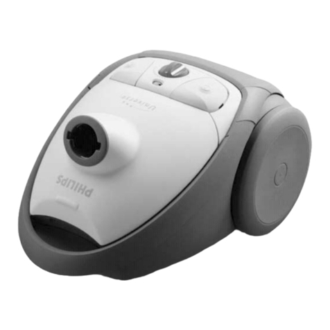
FC6844
DISASSEMBLY- AND RE-ASSEMBLY ADVISE
Motor unit:
- To open the motor unit,
remove the inlay by pressing
the inlay on the cord winder
push-button and remove 2
screws (A). (The inlay is
mounted on the cover by
means of a snap
construction).
- Use a long Philips screwdriver 9965 000 08332 to remove
the 6 screws (B) of the lower housing / top housing.
(Holes in lower housing are 13 cm deep).
Accessories:
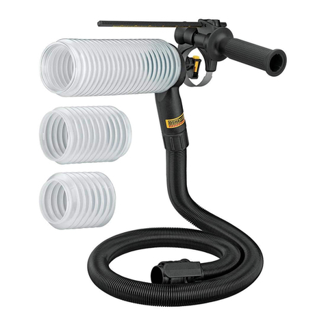
- See drawing for replacing of the shampoo pressure hose, for
example the pistol handgrip.
1
2
21
3
4
5
REPAIR INSTRUCTION
- The type no. plate is placed on the outside of the lower
housing (Item 38).
- For safety reasons, make sure that the cap clamps do not
come above the panel surface (Item 31) after replacing of
the switch (Item 30).
If the lower housing (Item 38) must be separated from the
top housing (Item 15) always replace waterproofing foam
(Item 22). Press hard on the housing during assembly of
this unit to prevent the foam from moving during assembly.
- The cord winder lever
(Item 14) must be assembled
through the top cover at an
angle (as shown in the figure)
to operate the cord winder.
- Depending on the national version, the cleaner has a 6.3
or 9.3 m cord. The spring unit (Item 101) is standard
provided with a 9.3 m spring.
- To demount the cord winder use TORX screw driver no.
T15, which is one of a set consisting of T20, T15, T10, T9,
T8 and T6 4822 395 50145.
- To check the shampoo circuit, it is neccessary to use the
male plug (Item 61) to open the valve in the female plug
(Item 32).
If the real half spring unit (Item 101) is replaced, shaft E
must be lubricated with silicone grease. Do not apply any
silicone grease to or spill any grease on terminals (Item 103)
or conductors (Item 102).
30˚±
2
1
A
A
2-6
