Phoenix Contact EV-CC-AC1-M3-CBC-RCM-ETH User manual

User manual
Installing and starting up the
EV Charge Control charging controller

2020-09-17
PHOENIX CONTACT GmbH & Co. KG • Flachsmarktstraße 8 • 32825 Blomberg • Germany
phoenixcontact.com
108191_en_04
Installing and starting up the EV Charge Control
charging controller
This user manual is valid for:
Designation Revision Order No.
EV-CC-AC1-M3-CBC-RCM-ETH
EV-CC-AC1-M3-CBC-RCM-ETH-3G
EV-CC-AC1-M3-RCM-ETH-XP
EV-CC-AC1-M3-RCM-ETH-3G-XP
1
1
0
0
1018701
1018702
1139449
1139452
User manual
UM EN EV-CC-AC1-M3-CBC-RCM-ETH, Revision 04

Table of contents
108191_en_04 PHOENIX CONTACT 3 / 100
Table of contents
1 For your safety ...........................................................................................................................5
1.1 Correct use............................................................................................................ 5
1.2 Safety notes .......................................................................................................... 5
1.3 Shutdown and disposal ......................................................................................... 6
2 Properties of the charging controller ..........................................................................................7
2.1 Ordering data ........................................................................................................ 8
2.2 Technical data ....................................................................................................... 8
2.3 Declaration of conformity in accordance with 2014/53/EU...................................12
3 Connections, indicators, and configuration switches ...............................................................13
3.1 Connections on the charging controller ............................................................... 13
3.2 Operating elements and indicators...................................................................... 15
3.3 Dimensions.......................................................................................................... 17
4 Mounting and startup ...............................................................................................................18
4.1 DIN rail mounting................................................................................................. 19
4.1.1 Mounting .............................................................................................. 19
4.1.2 Removal ............................................................................................... 19
4.2 Supply voltage connection...................................................................................20
4.3 Charging contactor connection............................................................................ 21
4.4 Connection of the current measuring transducer for residual current detection... 23
4.5 Connection of the vehicle charging connector and infrastructure charging socket ..
24
4.5.1 Vehicle charging connector .................................................................. 24
4.5.2 Infrastructure charging socket .............................................................. 25
4.6 Wiring of the digital inputs.................................................................................... 27
4.7 Wiring of the digital outputs ................................................................................. 29
4.8 RS-485 interface.................................................................................................. 31
4.8.1 Connecting the energy measuring device ............................................ 31
4.8.2 Connecting an RFID card reader ......................................................... 33
5 Cellular interface ......................................................................................................................35
6 Basics of signal contacts and charging sequences ..................................................................36
6.1 Control Pilot signal............................................................................................... 36
6.2 Proximity signal (Proximity Plug) ......................................................................... 41

EV Charge Control
4 / 100 PHOENIX CONTACT 108191_en_04
7 OCPP backend connection ......................................................................................................42
8 Status indicator and configuration via web server ....................................................................46
8.1 Connecting the charging controller to the PC ...................................................... 46
8.2 “Status” tab.......................................................................................................... 47
8.3 “Network” tab for Ethernet ................................................................................... 52
8.4 “Network” tab for cellular...................................................................................... 54
8.5 “Configuration” tab............................................................................................... 57
8.6 “Energy Meter” tab............................................................................................... 60
8.7 “Card Reader” tab................................................................................................ 65
8.8 “Remote Control” tab ........................................................................................... 67
9 Modbus description .................................................................................................................70
9.1 Modbus register types .........................................................................................70
9.2 Register assignment............................................................................................ 71
9.3 Function assignment of input and output registers .............................................. 90
A Appendix for document lists......................................................................................................93
A 1 List of figures ....................................................................................................... 93
A 2 List of tables ........................................................................................................ 95
A 3 Index.................................................................................................................... 97

For your safety
108191_en_04 PHOENIX CONTACT 5 / 100
1Foryoursafety
1.1 Correct use
The EV-CC-AC1-M3-CBC-RCM-ETH (-3G/-XP) charging controllers are designed exclu-
sively for use in electric vehicle charging stations in accordance with IEC 61851-1, mode 3.
The charging stations must be permanently connected to the power grid. No other uses are
permitted. Observe all applicable national requirements and regulations pertaining to the
design of charging stations.
This applies in particular when using charging connectors and infrastructure charging sock-
ets in accordance with IEC 62196.
Always use suitable housing that meets all applicable national requirements, e.g.,
IEC 61439-7. When selecting the housing, take into account the local ambient conditions
(temperatures, sunlight, humidity, pollution). Observe the limit values specified in the tech-
nical data (“Ambient conditions” on page 11) and the
requirements for the charging control-
ler. The housing design should satisfy these requirements.
When connecting to the power grid, observe all applicable national and regional require-
ments (e.g., IEC 60364-7-722).
1.2 Safety notes
WARNING: Startup only by specialist personnel
The charging controller must only be installed, operated, and maintained by qualified
electricians. Follow the installation instructions as described. When installing and op-
erating charging stations for electric vehicles, observe the applicable regulations and
safety directives. The safety data can be found in this user manual and in the certifi-
cates, i.e., the conformity assessment and additional approvals where applicable.
For further information, visit phoenixcontact.com/product/1018701
WARNING: Dangerous contact voltage
You may only install/remove and configure the device when the power supply is dis-
connected. Only operate the device in closed housing that protects against electrical
shock.
Provide a disconnecting device for disconnecting the charging station from the volt-
age.
NOTE: Electrostatic discharge
Electrostatic discharge can damage or destroy components. When handling the de-
vice, observe the necessary safety precautions against electrostatic discharge (ESD)
in accordance with EN 61340-5-1 and IEC 61340-5-1.

EV Charge Control
6 / 100 PHOENIX CONTACT 108191_en_04
Operation only in suitable housing
Only operate the device in a housing that meets the requirements for charging stations. Only
operate the device in conjunction with adequate housing.
The IP20 degree of protection (IEC 60529/EN 60529) of the device is intended for use in a
clean and dry environment. Only use the device in an environment that does not exceed pol-
lution degree 2 in accordance with IEC 60664-1.
If the device is to be used for an outdoor charging infrastructure, you can achieve pollution
degree 2 in the microenvironment, for example, by using housing with IP5X degree of pro-
tection in accordance with IEC 60529.
Do not subject the device to any strain or load that exceeds the limits described.
Do not open or modify the device
With the exception of configuration, opening or modifying the device is not permitted. Do not
repair the device yourself; replace it with an equivalent device instead. Only the manufac-
turer is permitted to repair the device.
1.3 Shutdown and disposal
Shutdown
For shutdown, the device must be disconnected from the mains voltage. Only remove the
device when disconnected from the voltage.
Provide a disconnecting device for disconnecting the charging station from the voltage.
Disposal
Do not dispose of the device with household waste; it should instead be disposed of in ac-
cordance with the currently applicable national regulations.

Properties of the charging controller
108191_en_04 PHOENIX CONTACT 7 / 100
2 Properties of the charging controller
The EV Charge Control charging controller is used to control and monitor the charging of
electric vehicles on the AC power grid in mode 3 in accordance with IEC 61851-1. It is inte-
grated into a defined charging infrastructure which is permanently connected to the power
grid. It monitors the Control Pilot and Proximity Plug signals in accordance with
IEC 61851-1.
The charging controller is responsible for status-dependent control of the switching element
which is used to establish the connection between the power grid and the electric vehicle.
It is equipped with a residual current sensor that interrupts the charging process when re-
sidual DC currents occur.
The charging controller can be used to activate or deactivate the charging connector lock in
the charging station according to the status. It features a serial interface that can be used to
connect energy measuring devices and RFID card readers.
In addition, the charging controller is available in versions with Ethernet or 3G cellular inter-
faces. The charging controller can communicate with a central management system via an
OCPP interface (via OCPP 1.6J, JSON).
You can combine several charging controllers to create a master/slave group. This group
can communicate with the central management system via the master using the OCPP pro-
tocol.
Technical features
– Evaluation and control of the Control Pilot signal in accordance with IEC 61851-1
– Evaluation of the Proximity signal in accordance with IEC 61851-1
– Connection and disconnection of the charging current to the vehicle
– 6 mA DC/30 mA AC residual current detection and automatic shutdown in the event of
an error
– Activation of the charging connector lock and automatic release if voltage is interrupted
– RS-485 communication interface/Modbus/RTU (master) for connecting an energy
measuring device and RFID card reader
– Ethernet interface (Modbus/TCP) for configuration, remote control, and status requests
– OCPP connection (OCPP 1.6J, JSON) via cellular or Ethernet interface
– Master/slave group for connecting several charging controllers via one OCPP connec-
tion
– Integrated load management in the master/slave group to protect the infrastructure
against overload
– Maximum charging current that can be configured: 6 A … 80 A
– Optional monitoring of charging currents
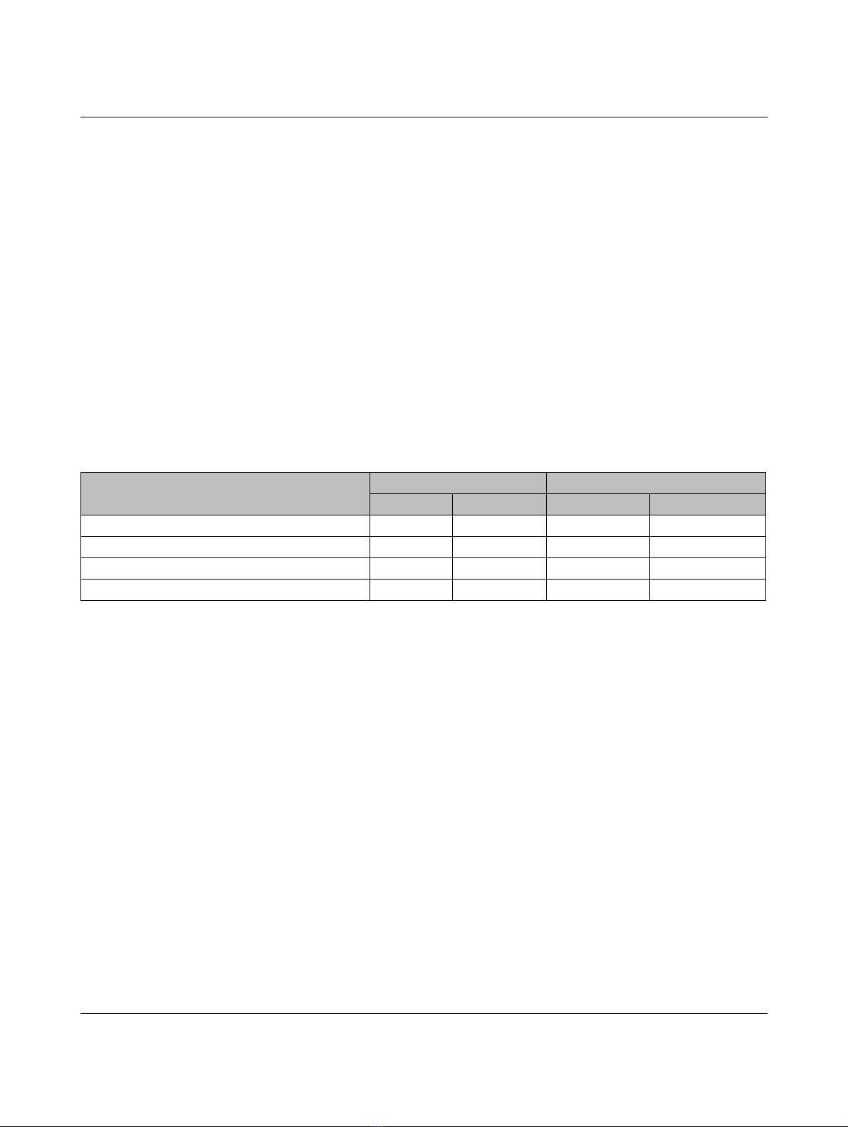
Table 2-1 Interfaces
Charging controller Communication OCPP 1.6J communication
Ethernet Cellular Ethernet Cellular
EV-CC-AC1-M3-CBC-RCM-ETH x – – –
EV-CC-AC1-M3-CBC-RCM-ETH-3G x x – x
EV-CC-AC1-M3-RCM-ETH-XP x – x –
EV-CC-AC1-M3-RCM-ETH-3G-XP x x x x

EV Charge Control
8 / 100 PHOENIX CONTACT 108191_en_04
– Digital inputs and outputs, can be configured
– Temperature range: -25°C ... +60°C
– Easy configuration directly at the device and via the integrated web server
2.1 Ordering data
2.2 Technical data
Description Typ e Order No. Pcs./Pkt.
Mode 3 charging controller, for charging electric vehicles
in accordance with IEC 61851-1 for charging case B and C
with integrated DC residual current monitoring and Ethernet
communication interface
EV-CC-AC1-M3-CBC-RCM-
ETH
1018701 1
Mode 3 charging controller, for charging electric vehicles
in accordance with IEC 61851-1 for charging case B and C
with integrated DC residual current monitoring, Ethernet and
3G cellular interface, OCPP 1.6J communication via cellular
EV-CC-AC1-M3-CBC-RCM-
ETH-3G
1018702 1
Mode 3 charging controller, for charging electric vehicles
in accordance with IEC 61851-1 for charging case B and C
with integrated DC residual current monitoring, Ethernet and
3G cellular interface, OCPP 1.6J communication via Ether-
net
EV-CC-AC1-M3-RCM-ETH-
XP
1139449 1
Mode 3 charging controller, for charging electric vehicles
in accordance with IEC 61851-1 for charging case B and C
with integrated DC residual current monitoring, Ethernet and
3G cellular interface, OCPP 1.6J communication via Ether-
net and cellular
EV-CC-AC1-M3-RCM-ETH-
3G-XP
1139452 1
General data
Dimensions 161.6mmx90mmx61mm
Weight 460 g
Power supply
Nominal voltage 230 V AC
Tolerance ±10%
Mains frequency 50/60 Hz
Power consumption, maximum 10 W
Power consumption, no load < 3 W

Properties of the charging controller
108191_en_04 PHOENIX CONTACT 9 / 100
Vehicle interface/infrastructure charging socket
Number of vehicle interfaces 1
Charging mode and case Mode 3, case B and C
Control Pilot IEC 61851-1, Edition 3, Annex A
Proximity IEC 61851-1, Edition 3, Annex B
Output voltage for controlling the locking actuator (2
source resistance)
12 V
Maximum current for locking control 1A
Adjustable actuation time for locking actuator 500 ms (default), max. 3 s
Feedback signal for locking Floating contact, closed if locking is successful
Locking behavior in the event of a power failure Automatic unlocking
Relay output for contactor control
Standard IEC 61810-1
Switching capacity 4000 VA
Switching voltage, maximum 250 V AC
Maximum current 16 A
Switching cycles 50000
Residual current monitoring
Rated frequency 0 Hz … 2000 Hz
Measuring range ±300 mA
Operate values for measuring sensors
Residual current ld1, IΔn1 6mADC
Residual current ld2, IΔn2 30 mA AC
Response time tae (for DC or > 15 Hz), for:
1xI
Δn
2xI
Δn
5xI
Δn
< 180 ms
<70ms
<20ms
Measuring current transducer
Cable feed-through diameter, measuring current transducer 15 mm
Length of connecting cable 0.2 m
Connection at main device (connector) 6-pos.
Load current, maximum 3 x 32 A (4 x 6 mm²), maximum
Standards IEC 60364-7-722
IEC 62752
DIN VDE 0100-722
(VDE 0100-722:2013-01)

EV Charge Control
10 / 100 PHOENIX CONTACT 108191_en_04
Digital inputs
Number 5
Nominal input voltage 12 V
Input resistance 3 k
Input voltage range <3V(off)/>9V(on)
Digital outputs
Number 4
Output voltage, feed-in via 12 V 8V…30V
Maximum output current per output, external feed-in 600 mA
Total maximum output current, internal 12 V feed-in 200 mA
RS-485 interface (RFID and energy measuring device)
Protocol Modbus/RTU
Transmission speed 4.8 kbps to 115.2 kbps, adjustable
Transmission mode (data bit, stop bit, parity) 8, N, 2
Ethernet interface, 100Base-TX in accordance with IEEE 802.3u / 10Base-T in accordance with IEEE 802.3
Connection method RJ45 jack
Protocol Modbus/TCP
EV-CC-...-XP: OCPP 1.6J (WebSockets)
Transmission speed 10/100 Mbps
Transmission distance 100 m
Cellular interface (EV-CC-AC1-M3-CBC-RCM-ETH-3G and ...3G-XP only)
Frequency bands
HSPA 900 MHz, 2100 MHz
GSM/GPRS/EDGE 850 MHz, 900 MHz, 1800 MHz, 1900 MHz
Maximum transmission power
UMTS/HSPA +24 dBm (power class 3)
GSM 850 Class 4 (2 W)
GSM 950 Class 4 (2 W)
GSM 1800 Class 1 (1 W)
GSM 1900 Class 1 (1 W)
Protocol OCPP 1.6J (WebSockets)
SIM card Micro SIM
Antenna connection SMA

Properties of the charging controller
108191_en_04 PHOENIX CONTACT 11 / 100
Connection data for power supply, power relay, CP, PP, locking
Connection method
Conductor cross section, rigid, min./max. 0.2 mm² ... 4 mm²
Conductor cross section, flexible, min./max. 0.2 mm² ... 2.5 mm²
Conductor cross section, flexible, with ferrule, without plas-
tic sleeve, min./max.
0.25 mm² ... 1.5 mm²
Conductor cross section, flexible, with ferrule, with plastic
sleeve, min./max.
0.25 mm² ... 1.5 mm²
Conductor cross section AWG AWG 24 … 12
Connection data for digital inputs and outputs and RS-485
Connection method
Conductor cross section, rigid, min./max. 0.14 mm² ... 1.5 mm²
Conductor cross section, flexible, min./max. 0.14 mm² ... 1 mm²
Conductor cross section, flexible, with ferrule, without plas-
tic sleeve, min./max.
0.25 mm² ... 0.5 mm²
Conductor cross section, flexible, with ferrule, with plastic
sleeve, min./max.
0.25 mm² ... 0.5 mm²
Conductor cross section AWG AWG 26 … 16
Ambient conditions
Degree of protection IP20
Ambient temperature range (operation) -25°C … +60°C
Ambient temperature range (storage) -40°C … +85°C
Humidity 30% … 95%, non-condensing
Overvoltage category / pollution degree II / 2 (IEC 60664-1)
Altitude (storage/operation) < 2000 m
Mounting position Any
Conformance/approvals
CE-compliant
Low Voltage Directive 2014/35/EU
Function and safety tests IEC 60950-1 / EN 60950-1
Air clearances and creepage distances IEC 60950-1 / EN 60950-1
Housing conformance with standards DIN 43880

EV Charge Control
12 / 100 PHOENIX CONTACT 108191_en_04
2.3 Declaration of conformity in accordance with
2014/53/EU
Phoenix Contact hereby declares that wireless system type
EV-CC-AC1-M3-CBC-RCM-ETH-3G complies with Directive 2014/53/EU.
The complete text of the EU declaration of conformity is available at the following address:
phoenixcontact.net/products/1018702.
Conformance with EMC Directive 2014/108/EU
Immunity test in accordance with EN 61000-6-2 Standard Criterion Test conditions
Electrostatic discharge (ESD) EN 61000-4-2 A2 kV / 4 kV contact discharge
2kV/4kV/8kVairdischarge
Electromagnetic HF field EN 61000-4-3 A 80 MHz … 1 GHz 10 V/m
1.4 GHz … 2 GHz 3 V/m
2GHz…2.7GHz1V/m
Fast transients (burst) EN 61000-4-4 AAC mains input (L,N,PE)
0.5 kV / 1 kV / 2 kV
Data cables, LAN 0.5 kV / 1 kV
Surge current loads (surge) EN 61000-4-5 A Mains input:
1kV/2kVasymmetrical:
cable to ground
0.5 kV / 1 kV symmetrical:
cable to cable
Conducted disturbance variables EN 61000-4-6 AFrequency range:
150 kHz … 80 MHz, voltage: 10 V,
80% AM, 1 kHz
Immunity to magnetic fields with mains frequency EN 61000-4-8 Met Test level:
30 A/m, 50 Hz / 60 Hz
Immunity to brief interruptions and voltage fluctua-
tions
EN 61000-4-11
A met
A met
A met
C met
Power cable:
Reduction for 20 ms
Reduction for 200 ms
Reduction for 500 ms
Reduction for 5000 ms
Noise emission test in acc. with EN 61000-6-3 Standard Result Test conditions
Radio interference voltage EN 61000-6-3 Met Network interconnection point:
150 kHz … 30 MHz
Radio interference voltage EN 61000-6-3 Met Telecommunications connections:
150 kHz … 30 MHz
Radio noise field strength EN 61000-6-3 Met 30 MHz … 1 GHz
1GHz…6GHz
Measurement of low-frequency harmonic currents EN 61000-6-2 Met Class A
Measurement of voltage fluctuations and flicker in
low-voltage networks
EN 61000-6-3 Met Pst < 0.25

Connections, indicators, and configuration switches
108191_en_04 PHOENIX CONTACT 13 / 100
3 Connections, indicators, and configuration switches
3.1 Connections on the charging controller
Figure 3-1 Connections on the charging controller
C4 C3
C2 C1
CT
EV Charge Control
EV-CC-AC1-M3-CBC-RCM
IEC 61815-1, Mode 3
0
9
8
7
6
5
4
3
2
1
NL
PEPE
R1 R2
CP PX
ʾˆ˅
ʿˀˁ˂˃˄
Table 3-1 Connections
No.
Name Meaning Description
1C1 Contactor 1 Control of load contactor 230 V AC, 16 A
C2 Contactor 2
CT Contactor test Contactor monitoring, checks the output signal for voltages on completion of the
charging process
2L Line Phase, power grid 230 V AC
NNeutral Neutral conductor, power grid
PE Protective
earth
Functional ground connected to protective earth ground
PE
3Ethernet RJ45 jack for 100Base-TX Ethernet interface

EV Charge Control
14 / 100 PHOENIX CONTACT 108191_en_04
For further information on the configuration options for the digital inputs and outputs,
please refer to “Status indicator and configuration via web server” on page 46.
4 12 V Power Output 12 V DC, max. 200 mA
LD Lock detection Digital input, can be configured via web
server or Modbus
Default: evaluation of locking feedback,
activation via DIP D6
EN Enable Default: enable charging process,
activation via DIP D7
ML Manual lock Default: manual locking, activation via
DIP D9
XR External release Default: charging station availability.
Activation via DIP D8.
IN Input Default: charging current 16 A
ARS-485 - A Connection of external energy/power measuring devices and RFID card readers
with Modbus/RTU protocol
BRS-485 - B
GND Ground System ground Connected to protective earth ground
CR Charger ready Digital output, can be configured via
web server or Modbus
Default: set when PWM is enabled
VR Vehicle ready Default: set when the vehicle is ready
(status C or D)
LR Lock request Default: set as long as locking is to re-
main active
ER Error Default: set when errors occur (status E
or status F)
12a Auxiliary power Supply input of the outputs 8 V DC… 30 V DC
5Residual current monitoring Dedicated connection for the supplied residual current sensor
6SIM Micro SIM card slot for cellular
7R1 Retaining Control voltage of locking actuator
R2
CP Control Pilot Pilot conductor signal Communication between charging sta-
tion and vehicle in accordance with
IEC 61851-1
PX Proximity Test signal Current carrying capacity of the con-
nected charging connector and
charging cable in accordance with
IEC 61851-1
8C3 Contactor 3 Relay output, reserved for future appli-
cations
230 V AC, 16 A
C4 Contactor 4
9Antenna SMA antenna connector for cellular connection
Table 3-1 Connections [...]
No.
Name Meaning Description

Connections, indicators, and configuration switches
108191_en_04 PHOENIX CONTACT 15 / 100
3.2 Operating elements and indicators
Figure 3-2 Operating elements and indicators
Changes to the DIP configuration only take effect after a charging controller restart.
1DIP switch 3Rotary coding switch
2LED indicators 4Reset button
C4 C3
C2 C1
CT
0
9
8
7
6
5
4
3
2
1
ʿ
ˀ
ˁ1
Table 3-2 DIP switches
No
.
DIP Name Meaning
11 Proximity ON Proximity value of the charging connector is evaluated (charging case B)
OFF Proximity value of the charging connector is not evaluated (charging case C)
2Reject charging cable ON Reject connector/cable with low current carrying capacity
OFF Reject connector/cable with low current carrying capacity
3Reject charging cable Only relevant if DIP 2 = ON
ON Reject 13 A connector/cable
OFF Reject 13 A and 20 A connector/cable
4Activate locking ON Lock charging connector
OFF Do not lock charging connector
5Reserved for future
applications
ON
OFF
6Locking feedback ON Evaluate locking feedback via digital input (default: input LD)
OFF Do not evaluate locking feedback
7Enable charging pro-
cess
ON Enable charging process via digital input (default: input EN)
OFF Enabling of charging process via digital input not required
8Charging station
availability
ON High signal at digital input (default: input XR) required, otherwise status F,
charging station not available
OFF High signal at digital input not required
9Manual locking ON Manual locking through High signal at digital input (default: input ML)
OFF Automatic locking in status B, vehicle connected
10 Enable via Ethernet ON Enable charging process and charging station availability via Ethernet
(Modbus/web server), RFID card with locally stored release list or via OCPP
backend
OFF Enabling of charging process and charging station availability via Ethernet
(Modbus/web server) not required

EV Charge Control
16 / 100 PHOENIX CONTACT 108191_en_04
Table 3-3 LED indicators
No. Color Meaning
2Green Power Flashes when charging controller is ready for operation
Red Error Lights up in the event of errors
Yellow Connect Flashes when valid charging connector is detected.
Permanently on when the charging connector is locked
in the charging socket.
Green Ready Flashes 1 s: vehicle is connected
Flashes 1/2 s: charging enabled (PWM signal on)
Permanent: charging contactor closed
Red/
green
Modem sta-
tus
Red: no connection to server
Green: connected to server
Table 3-4 Rotary coding switch
No. Position Meaning
30 PWM signal at 5%, necessary for digital communication
1Maximum current 6 A
2Maximum current 10 A
3Maximum current 13 A
4Maximum current 16 A
5Maximum current 20 A
6Maximum current 32 A
7Maximum current 63 A
8Maximum current 70 A
9Maximum current 80 A
Table 3-5 Reset button
No. Name Function
4Reset Pressing once: device restart
Pressing > 10 s: reset to factory default settings

EV Charge Control
18 / 100 PHOENIX CONTACT 108191_en_04
4 Mounting and startup
WARNING: Risk of electric shock
Only connect the charging controller or charging station to the supply line while it is
disconnected from the power supply.
When installing the device, provide a circuit breaker which is marked as the discon-
necting device for this device.
The circuit breaker must be suitably located and easily accessible to the user.
Only qualified personnel may set up and start up the device. The personnel must be
familiar with the necessary safety precautions. Observe the relevant requirements for
setting up and starting up a charging infrastructure, and, in particular, the applicable
safety regulations.
NOTE: Electrostatic discharge
Electrostatic discharge can damage or destroy components. When handling the de-
vice, observe the necessary safety precautions against electrostatic discharge (ESD)
in accordance with EN 61340-5-1 and IEC 61340-5-1.

Mounting and startup
108191_en_04 PHOENIX CONTACT 19 / 100
4.1 DIN rail mounting
4.1.1 Mounting
Figure 4-1 Mounting on a DIN rail
• Place the device onto the DIN rail from above.
• Push the front of the device toward the mounting surface until it audibly snaps into
place.
4.1.2 Removal
Figure 4-2 Removal from the DIN rail
• Push down the locking latch using a screwdriver, needle-nose pliers or similar.
• Pull the bottom edge of the device slightly away from the mounting surface.
• Pull the device diagonally upward from the DIN rail.
Click

EV Charge Control
20 / 100 PHOENIX CONTACT 108191_en_04
4.2 Supply voltage connection
NOTE: Risk of damage to the device
The power supply to the device must be protected against overcurrent up to 6 A, max-
imum.
Figure 4-3 Connecting the supply voltage and charging contactor
• Connect the supply voltage to the device via terminal blocks N, L, and PE (connection
block 1, see Figure 3-1 on page 13).
C4 C3
C2 C1
CT
EV Charge Control
EV-CC-AC1-M3-CBC-RCM
IEC 61815-1, Mode 3
0
9
8
7
6
5
4
3
2
1
NL
PEPE
R1 R2
CP PX
N
PE
L, L1-L3
230 V
135
246
1A
2A
7
8
This manual suits for next models
3
Table of contents
Other Phoenix Contact Automobile Accessories manuals