Phoenix Mecano DEWERT OKIN IPROXX SM User guide

System Instructions
for
Handset
IPROXX SM/SM+/SMP
®
S y s t e m I n s t r u c t i o n s
Issue
02/2013
02/2013
ID No. 56171
02/2013
ID No. 56170

IPROXX SM/SM+/SMP
®
2
Contents
General Information.................................................................................... page 2
Designated Use........................................................................................... page 3
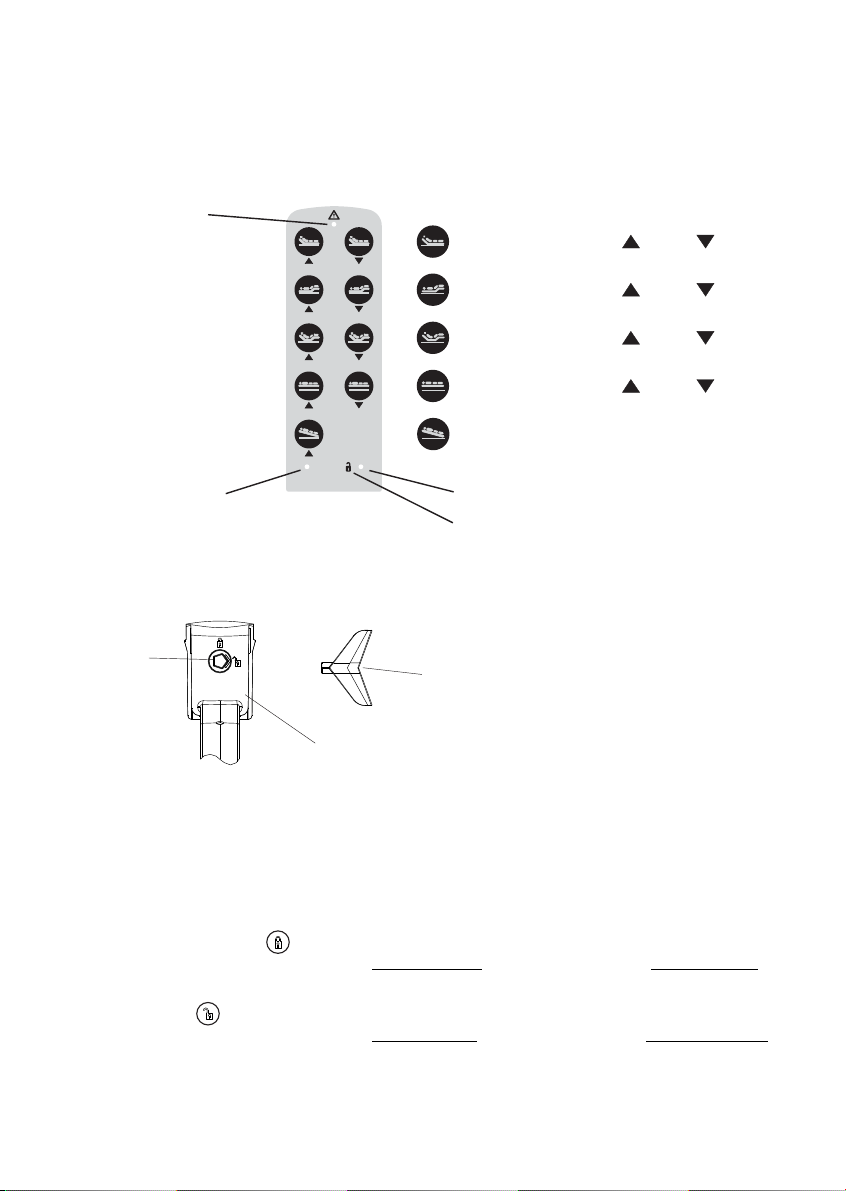
Key Configuration IPROXX SM.................................................................. page 4
Function of the Locking Device IPROXX SM............................................. page 4
Function Diagram IPROXX SM................................................................. page 5
Function of the Display................................................................................ page 5
Key Configuration page
Function of the Locking Device page
Function Diagram page
Function of the Display page
Key Configuration page
Function of the Locking Device page
Function Diagram page
Function of the Display page
Trouble-shooter’s Guide page
EC Declaration of Conformity page
®
®
®
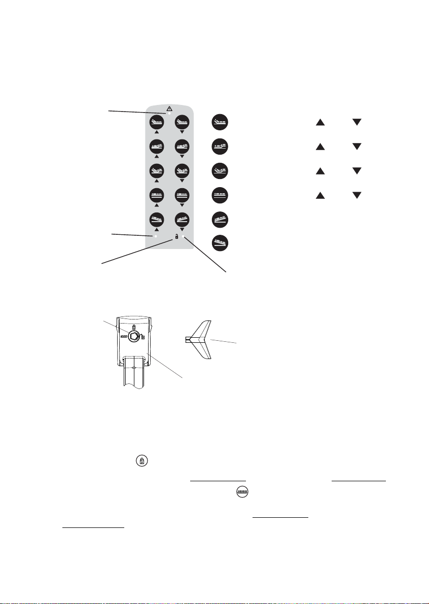
IPROXX SM+............................................................... 6
IPROXX SM+......................................... . 6
IPROXX SM+............................................................... 7
................................................................................ 8
IPROXX SMP................................................................ 9
IPROXX SMP........................................... 9
IPROXX SMP............................................................... 10
................................................................................ 11
Maintenance and Repairs............................................................................ page 12
.............................................................................. 13
Cleaning, Disposal...................................................................................... page 14
...................................................................... 15
®
®
®
®
®
®
General Information
These System Instructions are intended for the manufacturer of the end product and not for
the end user, the latter case requiring Operating Instructions, Directions for Use combined
with the complete drive system.
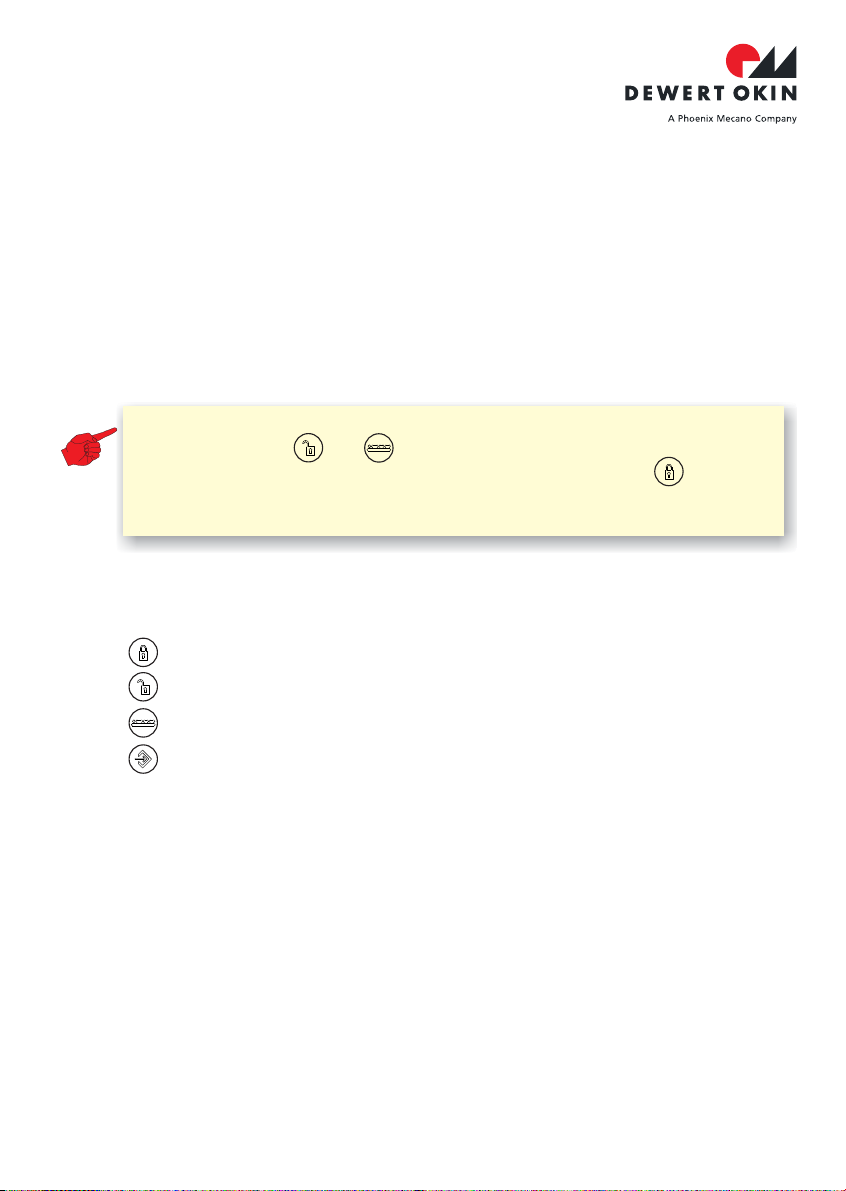
Note: magnetic objects and strong
magnetic fields
Keep the handset well away from
. The integrated locking device may accidentally be
activated or deactivated.
02/2013
ID No. 56171
02/2013
ID No. 56170

3
Handset locked
Handset released (SM/SM+/SMP)
released (SM+/SMP)
(SMP)
(SM/SM+/SMP)
Patient functions
Change Mode for nursing staff / care personnel
General symbols on the back of the handset
In order to guarantee single-fault protection you can lock the actuator movements via the
integrated locking device. In doing so, the motor circuits are disconnected by
electromechanic switch elements.
turn the locking switch to mode "locked",
check this by activating the adjustment key,
if locking is activated but movements will still be possible please exchange handset
for a new one
?
?
?
.
Information on battery power
?If you are operating your system on battery power then observe the following notice.
Designated Use
The Handset is with DEWERT drive control unit of Type
CARE (L), HOSP (L), i.e. MCL, SGAG, etc.
IPROXX intended for connect
®
The Handset IPROXX®is ...
in the proximity ,
in an environment where or gases or vapours
(e.g. anaesthetics) are likely to occur,
in a damp environment, i.e. outdoors or
in beds intended for cleaning in wash tunnels.
not intended for use
high-frequency surgical equipment and defibrillators
inflammable explosive
?
?
?
?
Note:
IPROXX
After it has been used to move your application (in the turnkey lock
positions or ), the Handset handset should be
turned back to its locked position (turnkey lock position ). This
prevents the system from gradually discharging when the battery is
connected!
®
02/2013
ID No. 56171
02/2013
ID No. 56170

4
IPROXX SM/SM+/SMP
®
Handset IPROXX SM
®
Key Configuration
IPROXX SMExample: Handset with 9 adjustment keys.
®
Function LED
Mode LED
Lock symbol
Power-ON LED
Backrest up
Footrest up
down
down
Stroke adjustment up
Reset
Back+footrest
down
down
Antitrendelenburg
up
Function of the locking device
turning the socket wrench IPROXX handset 2 modes can be
released or locked.
DEWERT control unit
DEWERT drive
turning the socket wrench,
released
By on the back of the ,
To put the handset into operation, connect it to a or a
with integral control PCB. The keypad of the plugged in handset is
completely locked (Mode locked).
The Mode LED next to the lock , the Power-ON LED
By the adjustment functions on the handset can be
, these vary depending on the model
The Mode LED next to the lock , the Power-ON LED
®
?
?
1)
1)
doesn’t glow glows dimly.
glows green glows brightly
1) Consult your customer contact beforehand in order to prevent any possible to the product.damage
(Mode released).
.
Rotary lock Socket wrench
Back of handset
Back of IPROXX SM handset
®
Power On
02/2013
ID No. 56171
02/2013
ID No. 56170

5
Function Diagram IPROXX SM
®
Putting into operation
Connect the handset to the DEWERT system.
Power On
off
Power OnPower On
green
Functions of the display
Battery-powered operation
with battery charging circuit
without battery charging circuit
Function LED - LED when a key is pressed,
visual display of first-error security.
Power-ON LED - LED when mains / battery voltage available
- (mains voltage not available)
LED when key is pressed
-
LED when battery is charging.
LED when battery is fully charged or is not
connected during mains operation.
-
LED when connected to the mains.
glows green
glows constantly
glows only
flashes yellow
glows constantly
glows constantly
Socket wrench turned to , h
Mode LED
andset is completely locked.
. Power-ON LED .doesn’t glow glows dimly
Socket wrench turned to ,
Mode LED .
handset adjustment functions are
released.
Power-ON LEDglows green glows brightly.
Mode locked
Mode released
02/2013
ID No. 56171
02/2013
ID No. 56170

6
IPROXX SM/SM+/SMP
®
Handset IPROXX SM+
®
Key Configuration
IPROXX SM+Example: Handset with 10 adjustment keys.
®
Function of the locking device
turning the socket wrench IPROXX handset modes can be
released or locked.
DEWERT control unit
DEWERT drive
By on the back of the , 3
To put the handset into operation, connect it to a or a
with integral control PCB. The keypad of the plugged in handset
is completely locked (Mode locked).
The Mode LED next to the lock , the Power-ON LED
®
?
?
1)
1)
doesn’t glow glows dimly.
glows green
glows brightly
1) Consult your customer contact beforehand in order to prevent any possible to the product.damage
By turning the socket wrench to the symbol (patient function), the adjustment
functions on the handset can be released, these vary depending on the model
(Mode Patient)
.
.
Power On
Function LED
Trendelenburg
Antitrendelenburg
Power-ON LED
Back of IPROXX SM+ handset
®
Rotary lock
Socket wrench
Back of handset
Mode LED
Lock symbol
Backrest up
Footrest up
down
down
Stroke adjustment up
Reset
Back+footrest down
down
up
02/2013
ID No. 56171
02/2013
ID No. 56170

7
?By to the symbol ,
the adjustment functions on the handset can be released for the
. These functions vary depending on the model
The Mode LED next to the lock , the Power-ON LED
turning the socket wrench
nursing staff /
care personnel
glows yellow glows brightly
(Mode released).
.
Putting into operation
Connect the handset to the DEWERT system.
Power On
off
green
Power On
Power On
yellow
Function Diagram IPROXX SM+
®
Socket wrench turned to , handset is completely locked.
Mode LED . Power-ON LED .doesn’t glow glows dimly
By turning the socket wrench to , the adjustment functions on the
handset are released for the
Mode LED . Power-ON LED
nursing staff / care personnel.
glows yellow glows brightly.
By turning the socket wrench to the symbol (patient function), the
adjustment functions on the handset can be released for the .
Mode LED , Power-ON LED
patient
glows green glows brightly.
Mode locked
Mode released
Mode Patient
02/2013
ID No. 56171
02/2013
ID No. 56170

IPROXX SM/SM+/SMP
®
8
Function of the display
Battery-powered operation
with battery charging circuit
without battery charging circuit
Function LED - LED when a key is pressed,
visual display of first-error security.
Power-ON LED - LED when mains / battery voltage available
- (mains voltage not available)
LED when key is pressed
-
LED when battery is charging.
LED when battery is fully charged or is
not connected during mains operation.
-
LED when connected to the mains.
glows green
glows constantly
glows only
flashes yellow
glows constantly
glows constantly
02/2013
ID No. 56171
02/2013
ID No. 56170

Power OnPower On
9
Handset IPROXX SMP
®
Key Configuration
IPROXX SMPExample: Handset with 10 adjustment keys.
®
Function LED
Trendelenburg
Antitrendelenburg
Power-ON LED
Back of IPROXX SMP handset
®
Rotary lock
Socket wrench
Back of handset
Status LED
Backrest up
Footrest up
down
down
Stroke adjustment up
Reset
Back+footrest down
up
down
02/2013
ID No. 56171
02/2013
ID No. 56170

IPROXX SM/SM+/SMP
®
10
Function of the locking device
turning the socket wrench IPROXX handset 4 modes can be
released or locked.
DEWERT control unit
DEWERT drive
turning the socket wrench
nursing staff / care personnel
turning the socket wrench
By on the back of the ,
To put the handset into operation, connect it to a or a
with integral control PCB. The keyboard of the plugged in handset
is completely locked (Mode locked).
The Mode LED next to the lock , the Power-ON LED
By to the symbol , the adjustment functions on the
handset can be released for the . These functions
vary depending on the model (Mode released). The Status LED's between all the
adjustment keys , the Power-ON LED
Programming y pressing an adjustment key (UP or DOWN) unlocks or locks the
corresponding key pair. If the Status LED between the adjustment keys
, the function on the IPROXX handset is released, the Power-ON LED
By to the symbol (patient function), the
programmed adjustment functions on the IPROXX handset are released for the
patient The Status LED's between the respective pairs of keys
when the function is released. The Status LED's when
the key pair is locked. he Power-ON LED
®
?
?
?
?
1)
1)
doesn’t glow glows dimly.
glow yellow glows brightly
glows
yellow
glows brightly
glow yellow do not glow
glows brightly
1) Consult your customer contact beforehand in order to prevent any possible to the product.damage
.
.
.
By to the symbol (programming), the adjustment
functions on the handset can be programmed for the patient (Mode Programming).
These functions are released or locked in pairs.
: B
(Mode Patient).
T
turning the socket wrench
02/2013
ID No. 56171
02/2013
ID No. 56170

11
Putting into operation
Connect the handset to the DEWERT system.
Function Diagram IPROXX SMP
®
Socket wrench turned to handset is completely locked.
Power-ON LED .glows dimly
,
Status LED ,doesn’t glow
Socket wrench turned to the adjustment functions on the handset
can be released for the .
Power-ON LED
nursing staff / care personnel
glows brightly
,
.Status LED ,glows yellow
Socket wrench turned to the programmed
adjustment functions on the IPROXX handset are released resp.
locked for the patien
Power-ON LED
®
glows brightly
(patient function),
t.
Status LED’s of released functions Status LED’s of locked
functions ,
glow yellow
do not glow
,
.
Socket wrench turned to
Power-ON LED
®
glows brightly
(Programming) and pressed the respective
adjustment key, the adjustment functions on the IPROXX can be
programmed in pairs for the patient (released resp. locked).
Status LED’s of released function(s) ,glow yellow
.
Mode locked
Mode Patient
Mode released
Mode Progamming
02/2013
ID No. 56171
02/2013
ID No. 56170

12
IPROXX SM/SM+/SMP
®
Function of the display
Battery-powered operation
with battery charging circuit
without battery charging circuit
Function LED - LED when a key is pressed,
visual display of first-error security.
LED when mains / battery voltage available
(mains voltage not available)
LED when key is pressed
-
LED when battery is charging.
LED when battery is fully charged or is not
connected during mains operation.
-
LED when connected to the mains.
LED's the corresponding adjustment keys are
released.
glows green
glows constantly
glows only
flashes yellow
glows constantly
glows constantly
glow yellow,
Power-ON LED
Status LED (SMP)
- LED's the corresponding keys are locked.
-
-
-
do not glow,
Maintenance and Repairs
Check
In addition to the above, the following checks should be carried out at shorter intervals:
At regular intervals carry out the inspections in accordance with the BGV A3 (Instruction of
the Professional Trade Association). The inspections must be performed by an electrical
specialist.
The recommended inspection period in accordance with the BGV A3 is:
Check the housing for cracks and fractures and the connection lead for signs of
pinching and shearing-off. Also check the strain relief with kink protection, in
particular after each case of mechanical loading.
the leakage currents (by a specialist).
the Handset.
6 months
Regular visual checks for damage of all kinds
Regular checks of
Regular functional checks of
.
?
?
?
02/2013
ID No. 56171
02/2013
ID No. 56170

13
Trouble-shooter’s Guide to Detect and
Eliminate Faults
The following table has been developed to help you detect and eliminate common faults. If
you come across a fault that is not listed here, please contact your supplier.
Mode LED / Lock LED
glows in the locked
state
- Fault in the handset - Contact your supplier/
dealer
No adjustment can be
made
- Use socket wrench to
release the handset
- Handset is locked
- Control unit / drive defective
-
-
If necessary, check the locking
device
Check voltage supply
- Check connection leads
- Battery discharged or not
connected
The Function LED
doesn’t glow when a
key is pressed (control
unit / drive with first-
error security only)
- Control unit / drive or handset
defective
- Contact your supplier/
dealer
Problem Possible Cause Remedy
The Function LED
glows all the time
(control unit / drive
with first-error security
only)
- Control unit / drive defective - Contact your supplier/
dealer
Mode LED / Lock LED
doesn’t glow in the
released state
-
-
Fault in the handset
Fault in the control unit
- Contact your supplier/
dealer
Power-ON LED does
not glow. (Handset is
locked, exception
battery-powered
operation)
- Fault in the handset - Contact your supplier/
dealer
Power-ON LED glows
brightly.(Handset is
locked)
- Fault in the handset - Contact your supplier/
Dealer
02/2013
ID No. 56171
02/2013
ID No. 56170

14
IPROXX SM/SM+/SMP
®
Cleaning
handsetThe was designed so that it would be easy to clean. Its smooth surfaces
simplify the cleaning process.
1 Be sure to disconnect the handset cable from the drive or control unit before you start
cleaning.
2 Clean the handset using a moist cloth.
3 Be sure that you do not damage the connecting cables during the cleaning.
Never clean the handset in an automated washing system or with a high-pressure cleaner.
Do not allow fluids to penetrate the handset. Damage to the handset could result.
Do not use a cleanser that contains benzene, alcohol or similar solvents.
The handset consists of electronic components, cables and metal and plastic
parts. You should observe all corresponding national and regional environmental regulations
when disposing of the handset.
The disposal of the end product is regulated in Germany by Elektro-G, internationally by the
EU Directive 2002/95/EC (RoHS, from 1 Jul. 2006), Directive 2011/65/EU (RoHS,
from 3 Jan. 2013) or by any applicable national laws and regulations. (The end product is
not regulated by the EU Directive 2002/96/EC (WEEE) and its amendment EU Directive
2003/108/EC.)
IPROXX®
IPROXX
IPROXX
IPROXX
®
®
®
®
Disposal
The IPROXX handset should not be disposed of with normal household waste!
02/2013
ID No. 56171
02/2013
ID No. 56170

15
EC Declarations
Declaration of Conformity
DewertOkin GmbH
Weststraße 1
32278 Kirchlengern
Germany
IPROXX
EC-EMC Directive 2004/108/EC
RoHS Directive 2011/65/EU of the European Parliament and of the
Council of 8 June 2011 on the restriction of the use of certain
hazardous substances in electrical and electronic equipment
In compliance with Appendix IV of the EU EMC Directive 2004/108/EC
In compliance with Appendix VI of the EU RoHS Directive 2011/65/EU
The manufacturer:
declares that the following product
complies with the requirements of the following EC directives:
Applied standards:
This declaration of conformity is no longer valid if constructional changes are made which
significantly change the product (i.e., which influence the technical specifications found in
the instructions or the intended use)!
Head of R & D
®with DEWERT drive system
Kirchlengern, Germany on 10 February, 2013 Sascha Koltzenburg
?
?
?
?
?
?
EN 55014-1/A1:2009
EN 55014-2/A2:2008
EN 61000-3-2/A2:2009
EN 61000-3-3:2008
EN 62233:2008
EN 1970/A1:2005, main section 5.12
02/2013
ID No. 56171
02/2013
ID No. 56170

DewertOkin GmbH
Weststraße 1
32278 Kirchlengern, Germany
Tel: +49 (0)5223/979-0
Fax: +49 (0)5223/75182
http://www.dewertokin.de
02/2013
ID No. 56171
02/2013
ID No. 56170
This manual suits for next models
2
Table of contents