Phoenix Mecano Rose EJB Series User manual

IM.EJB.X.01.2019 IECEx/ATEX Page 1
Instruction Manual for Power Distribution, Switchgear and Control
Assembly –EJB Series
All work on this Ex
-
equ
i
p
ment must be carried out only by qualified
Specialist personnel following EN/IEC 60079-14. Any subsequent
Modification must bewithin frameworkof this operation manual
The operating permit expires in the event of non-compliance!

IM.EJB.X.01.2019 IECEx/ATEX Page 2
Contents
1.0 Safety Instructions ..........................................................................................................................2
1.1 Safety Notes....................................................................................................................................2
1.2 Modification and alteration............................................................................................................3
2.0 Standards conformity …………………………….......................................................................................3
3.0 Function ..........................................................................................................................................3
4.0 Technical Data.................................................................................................................................4
5.0 Installation.......................................................................................................................................6
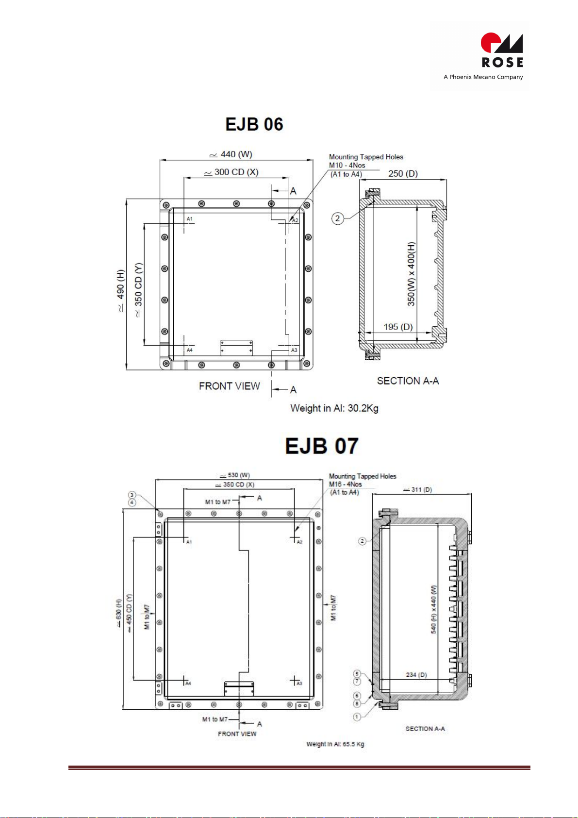
5.1 Dimensional drawings.....................................................................................................................6
5.2 Installation Conditions...................................................................................................................10
5.3 Mounting & operating positions....................................................................................................10
5.4 Electrical Connection.....................................................................................................................11
6.0 Commissioning ..............................................................................................................................12
7.0 Inspection, Maintenance, Overhaul and Repair.............................................................................12
7.1 Inspection and Maintenance .........................................................................................................12
7.2 Repair and Overhaul ......................................................................................................................12
8.0 Specific condition of use ................................................................................................................12
9.0 Technical Support………………………………………………………………………………………………………………………12
1.0 Safety Instructions
1.1 Safety notes
The target group of these instructions is electrical operatives and instructed staff
following EN/IEC 60079-14.
Operating permit expires in event of non-compliance.
Use the devices only for their intended purpose!
We cannotbe held liable for damage caused by incorrectorunauthorized
use or by non-compliance with these operating instructions.
Use the device only if it is undamaged.
Serious risk of injury!
Only original parts supplied by ROSE are permissible for spares and repair
work. Other spare parts can invalidate explosion protection.
The explosion group, temperature classand ambient temperature marked on the
enclosure must be observed!
Please look at marking on enclosure, it should be installed in zone, explosion
group, T Class & ambient temperature for which they are suitable.
We cannotbe held liable for damage caused by incorrectselection.
Any unauthorized work on the device is prohibited!
Installation, maintenance, overhaul and repair may only becarried out by
appropriately authorized and trained personnel.
Repairs affecting the explosion protection must onlybe carried out by ROSE or a
qualified authorized person in accordance with EN/IEC 60079-19!
Do not allow combustible dust deposit to form on enclosure!
Regular cleaning of dust deposit is recommended to avoid hot surface
becoming ignition risk.

IM.EJB.X.01.2019 IECEx/ATEX Page 3
Observe the following information during installation and operation
Remove all foreign bodies (e.g. uncertified plugs for transportation) from enclosure.
Any damage may compromise the explosion protection
National and local safety regulation
National and local accident prevention regulations
National and local assembly and installation regulations
Generally recognized technical regulations
Safety notes in this instruction manual
Characteristic values and related operating conditions on the rating plates and data
plates
Additional information plates on the device
1.2 Modification and alterations
Alteration and modifications to the device are not permitted!
Do not add terminals and components without consultation to manufacture.
Do not make additional cable or conduit entries.
We shall not take any liability or warranty obligations for damage resulting from
alterations and modifications.
2.0 StandardConformity
The equipment is tested and approved for explosion hazard area to
IEC 60079-0:2017 & EN IEC 60079-0:2018, IEC 60079-1:2014 & EN 60079-1:2014, IEC60079-
31:2013 & EN 60079-31:2014, IEC 60529:2013 & EN 60529:1992/A2:2013 standards and ATEX
Directive 2014/34/EU.
The recognized national conditions and stipulation concerning electrical equipment in hazardous
area must be considered while installing and operating explosion proof electrical equipment.
These enclosures can be used in hazardous area in Zones 1, 2, 21, 22.
They are not certified for Zone 0, 20.
3.0 Function
These enclosures are used as Power Distribution, Switchgear and Control assembly
enclosures. The protection technique allows using standard electrical products having
arcing or sparking components inside enclosure. These electrical components are
mounted & wired according to customer specification.
Use the device for its intended purpose only!
Otherwise, the manufacturer’s liability and warranty expires.
Use the device under operating conditions described in instruction manual.
The device can be used in areas subject to explosion hazards only according to this
instruction manual.
No changes tothe device impairing their explosion protection are permitted.
Install the device only if is undamaged, dry and clean.

IM.EJB.X.01.2019 IECEx/ATEX Page 4
4.0 Technical Data
Manufacturer: ROSE Systemtechnik GmbH
Erbeweg 13-15, 32457 Porta Westfalica,
GERMANY
Explosion Protection:
IECEx Gas: Ex db IIB+H2T6/T5/T4Gb
Dust: Ex tb IIIC T85⁰C/T100⁰C/T135⁰C Db
ATEX Gas: II 2 G Ex db IIB+H2T6/T5/T4Gb
Dust: II 2 D Ex tb IIIC T85⁰C/T100⁰C/T135⁰C Db
IECEx Certificate of Conformity No: IECEx DEK 18.0074 X
EC Type examination Certificate No: DEKRA 18ATEX0118 X
Electrical Data
Rated operation voltage: 1.1KV AC/DC (Declared voltage rating is nominal and item having higher
voltage rating may be populated as required in consultation with manufacturer.)
TYPE NO EJB 01 EJB 02 EJB 03 EJB 04 EJB 06 EJB 07 EJB 09 EJB 10
Max Rated Current (A) 76 125 232 269 415 850 935 1055
Max Conductor Size(mm2) 16 35 95 120 240 500 630 1000
Max PE Conductor Size
(mm2)
16
16
50
70
120
240
300
500
Ambient Temperature
“-60⁰C*/ -20⁰C ≤ Ta ≤ +40⁰C…..+110⁰C
*EJB 06, EJB 09 & EJB 10 are suitable for “-20⁰C” only, other types are suitable for both “-20⁰C and 60⁰C”.
Use equipment within ambient temperature marked on Ex label
Mechanical data
Enclosure: Marine grade copper free aluminum alloy
(Enclosures are available in stainless steel or cast iron on request)
ORing: Silicone
Finish: RAL 7035
(Enclosures are available in natural finish or electroplated on request)
Earthing: 1No External and 1No Internal
Degree of protection: IP66 as per IEC 60529:2013 & EN 60529:1992+A2:2013
Installation: 4 mounting holes
Number, size & location of entries
Number, size & location of entries shall be in combination as required within max permissible
limits in Metric as per ISO 965 or NPT as per ANSI/ASME B1.20.1 specified as per table. Generally,
these entries will be from sides of base. However, entries from rear of base can be provided as
required subject to
a) Total area of entries from all sides and rear shall not exceed total area of entries allowed from
all the four sides
b) All reinforcement provided in the base shall remain intact and
c) Min center to center distance shall be maintained as in case of entries from sides.

IM.EJB.X.01.2019 IECEx/ATEX Page 5
PERMISSIBLE ENTRIES FROM EACH SIDE
SIZE
SIDE
EJB 01
EJB 02
EJB 03
EJB 04
EJB 06
EJB 07
EJB 09
EJB
10
M20 or 1/2"NPT Shortside 04 06 08 20 21 36 54 55
Long side 06 08 10 25 24 46 84 90
M25 or 3/4"NPT Shortside 02 04 06 14 17 24 33 45
Long side 04 05 08 20 20 30 54 75
M32 or 1"NPT Shortside 01 03 04 12 11 20 28 30
Long side
02
04
05
14
12
26
43
50
M40 or 1.1/4"NPT
Short side
X
02
03
08
08
12
18
21
Long side X 03 03 11 10 15 28 33
M50 or 1.1/2"NPT
or 2”NPT Shortside X X 02 06 04 09 12 18
Long side X X 03 08 05 11 21 27
M63 or 2.1/2"NPT Shortside X X X 03 03 05 11 12
Long side X X X X 04 07 17 20
M75 or 3"NPT
Short side
X
X
X
02
03
04
06
08
Long side
X
X
X
X
03
05
09
14
M90 or3.1/2"NPT Shortside X X X X X X 05 07
Long side X X X X X X 08 11
M100 or 4"NPT Short side X X X X X X 05 04
Long side X X X X X X 07 08
Marking
*Note- Equipment may be marked as IIB or IIB+H2 as required. Equipment marking shall be completed by using type of
protection i, [i], m for certified equipment or component used for assembly and general aarangement drawing for
assembly will refer to applicable certificates.
TYPE T Class T6 T5 T4
Dust Temp
Marking T85⁰C T100⁰C T135⁰C
Maxambient
temp +40⁰C +50⁰C +60⁰C +40⁰C +50⁰C +55⁰C +60⁰C +75⁰C +40⁰C +50⁰C +60⁰C +90⁰C +110⁰C
EJB 01
Max Watt
Dissipation
60W X 36W X X 60W X 36W X X X 60W 36W
EJB 02 76W X 42W X X 76W X 42W X X X 76W 42W
EJB 03 87W X 60W X X 87W X 60W X X X 87W 60W
EJB04 190W 150W 105W 292W 230W 190W 185W 105W 530W 455W 390W 190W 105W
EJB06 209W 166W 114W 338W 260W 209W 206W 114W 584W 514W 436W 209W 114W
EJB07 365W 290W 205W 570W 440W 365W 320W 205W 1050W 890W 760W 365W 205W
EJB09 467W 319W 236W 728W 555W 467W 353W 236W 1238W 1145W 956W 467W 236W
EJB10 726W 568W 400W 1085W 864W 726W 712W 400W 2038W 1709W 1454W 726W 400W
Note:EJB 06,EJB 09 and EJB 10 aresuitablefor “-20⁰C” only, other types are suitable for both“-20⁰C and -60⁰C”.
Thread type i.e. Metric or NPT and size of threaded entry are marked on supplied enclosure by affixing
suitable sticker near each entry.

IM.EJB.X.01.2019 IECEx/ATEX Page 6
5.0 Installation
5.1 Dimensional drawings (All dimensions in mm) – subject to alterations

IM.EJB.X.01.2019 IECEx/ATEX Page 7

IM.EJB.X.01.2019 IECEx/ATEX Page 8

IM.EJB.X.01.2019 IECEx/ATEX Page 9

IM.EJB.X.01.2019 IECEx/ATEX Page 10
5.2 Installation conditions
Built in components
The T Class is dependent on power dissipation of components, wiring and Max ambient
temperature. Refer Technical data. No batteries & fans are permitted.
Only replacement of components built inside the enclosure is permitted. Any addition or
alternation without consultation to ROSE is not permitted and may lead to ignition risk.
Replacement of Display window is not possible.
5.3 Mounting and operating position
Mounting the enclosure
Mount the enclosure in vertical position by using four screws. Refer dimensional drawing
for mounting holes & mounting dimension.
Tighten the mounting screws properly.
Opening the enclosure
The enclosure lid is bolted. Use Allen key of appropriate size to open lid bolts.
Closing the enclosure
These enclosures are with/ without O ring in base. In case O ring is damaged, please
replace with supplies from ROSE.
In case O Ring is not provided, ingress protection is ensured by application of silicone
grease Anabond 662 or equivalent (e.g. Fuchs Renolit Unitemp 2).
To prevent corrosion of flange joint it is coated with silicone grease Anabond 662 or
equivalent. (e.g. Fuchs Renolit Unitemp 2).
Apply a coat of silicone grease Anabond 662 or equivalent (e.g. Fuchs Renolit Unitemp 2)
on flange of lid & base before closing.
Bolt the lid of enclosure and tighten the bolts using appropriate size of Allen keys. No
bolts should be missing or loose.
Lid bolts are of SS A2.70 grade. In case of replacement, replace by same size of same or
higher strength.
Danger due to not approved cable glands & accessories!
Only certified cable glands & accessories of required Ex protection shall be
used.
Each entry shall have no more than one thread adopter. A blanking element
shall not be used with a thread adopter.
In case of non-compliance explosion protection can no longer be guaranteed.
Danger due to open holes or unused cable entries on the enclosure!
If holes or unused cable entry is left open, explosion protection can no longer
be guaranteed.
Close open holes using stopping plugs approved for required type of
protection.

IM.EJB.X.01.2019 IECEx/ATEX Page 11
5.4 Electrical Connection
Internal wiring
Incorrect wiring inside enclosure!
Strictly adhere to wire size and length for which heat loss dissipation are
taken into account for permissible wattage for a given T Class. In case of
non-compliance explosion protection can no longer be guaranteed.
Strictly adhere to the creepage and clearance required.
Use only insulated wires of suitable voltage grade.
Mounting rails or components must be loosened and fastened properly.
External Wiring
Danger due to improper cables!
The cables must comply with IEC/EN 60079-14 and relevant regulation and
must have the required cross section.
Strictly adhere to cable size and length for which heat loss dissipation are
taken into account for permissible wattage for a given T Class and ambient
temperature.
In case of non-compliance explosion protection can no longer be
guaranteed.
Danger due to improper cable glands!
The cable glands shall be appropriate to cable type and size and with
suitable approval as per IEC/EN 60079-14.
Entry threads have been marked on enclosure by sticker, please use cable
gland of appropriate size and type.
In case of non-compliance explosion protection can no longer be
guaranteed.
Protective Earth (PE) and equipotential (EP) bonding conductor connection
Always connect the protective earth (PE) and equipotential (EP) bonding conductor!
The device is equipped with one internal and one external earthing stainless
steel screw, 1 No. tooth (Anti-rotational) washer and 2 No. plain washers.
Use ring type lug of suitable material and size to be affixed between 2 plain
washers.
The PE and EP conductor size shall be as under:
Cross-sectional area of
phase Conductor S mm2Minimum cross-
sectional area of PE
conductor in mm2
Minimum cross-sectional
area of the EP conductor in
mm2
S
≤ 16
S
Minimum 4mm2 or same as
PE conductor if it is intended
to serve as PE conductor also.
16 < S ≤ 35 16
S>35 0.5 S

IM.EJB.X.01.2019 IECEx/ATEX Page 12
6.0 Commissioning
Check the device before putting it into service!
To ensure proper operation the equipment must be checked prior to putting it in
service.
If the enclosure is connected incorrectly, explosion protection is no longer
guaranteed!
The device must be operated only with completely closed enclosures.
Before commissioning ensure that:
No components are damaged.
The equipment has been installed according to regulations.
There are no foreign bodies inside the device.
The specified tightening torques has been observed.
7.0 Inspection, Maintenance, Repair and Overhaul
7.1 Inspection and Maintenance:
Consult the relevant national regulations (e.g. IEC/EN 60079-17) to determine the type
and extent of inspections.
Plan the intervals such that any expected defects are detected promptly.
Risk of Electric Shock!
Before opening the device, disconnect it from power supply and wait for some
time to allow internal components to cool down.
7.2 Repair and Overhaul
Damaged enclosure cannot be repaired at site. Only control accessories, electrical components,
cable glands &accessories can be changed. Please follow IEC/EN 60079-19 for repair of damaged
enclosure. Only certified control accessories of Rose must be used.
8.0 Specific conditions ofuse:
For enclosures provided with a powder coating, liquid painting or
provided with a non-metallic nameplate and/or tagplate and intended
for use in Group III applications, the user shall minimize the risk from
electrostatic discharge by suitable selection and installation.
The flanged flame path of the cover differs from the values stated in EN
60079-1. Contact the manufacturer for information on the dimensions of
the flameproof joints.
The M6, M8, M10 and M12 fasteners are of grade A2-70 with a yield
stress of at least 450 MPa and shall be applied with a minimum torque
value of 11 Nm (M6), 28 Nm (M8), 58 Nm (M10) and 95 Nm (M12).
LED Indicating lamps, if assembled, are suitable for low risk of
mechanical danger i.e., 2 Joules.
Control Accessories i.e., indicating lamps, Push button and Rotary
actuators, if assembled, may pose risk of electrostatic discharge hence
clean with damp cloth only.
9.0 Technical Support:
ContactROSE Systemtechnik GmbH, Erbeweg 13-15, D-32457 Porta Westfalica,
GERMANY for technical support.
This manual suits for next models
8
Table of contents
Popular Power Distribution Unit manuals by other brands

YOKOGAWA
YOKOGAWA YEWSERIES 80 SDBS (Style S) user manual

West Mountain Radio
West Mountain Radio RIGrunner 4004USB manual

Vynco
Vynco VM17 Product information

Ingrasys
Ingrasys iPoMan 8000 user manual

Schulte Elektrotechnik
Schulte Elektrotechnik EVOline Port 1129 Operating and assembly instructions

Shure
Shure PA411 user guide