Phoenix DryRod 300 Series User manual

dryrod.com info@dryrod.com +1 414.973.3400 8711 West Port Avenue Milwaukee, WI 53224 Phoenix International
• Bench models provide large capacity storage for electrodes
• Door mounted thermometer oered for instant temperature indication
• Adjustable thermostatic control
• Single action door latch easily closes and can be locked
• Shelving provides fit for 50 lb cans
Type 300 Series
Electrode Stabilization Ovens
Part No. Description Options
Temperature
Range* Insulation Chamber Size
Capacity
(for 18" electrodes) Weight Dimensions
Type 300 Series Ovens with 10"
grounded heavy duty cord**
1200200 120/240V AC at 1000 watts
none
100°- 550°F
(38°- 288°C) +/-
25°F (14°C)
adjustable
thermostat
control with
indicator light
2"
fiberglass
18" diameter
x 19" deep
400 lb (182 kg)
accepts electrodes
up to 18"
90 lb
(41 kg) 29.5" x 22.5" x 22.5"
1200100 240/480V AC at 1000 watts
1200201 120/240V AC at 1000 watts with door mounted
thermometer installed
1200101 240/480V AC at 1000 watts
1200202 120/240V AC at 1000 watts wtih top stacking lugs
installed
1200102 240/480V AC at 1000 watts
1200203 120/240V AC at 1000 watts with door mounted
thermometer and top
stacking lugs installed1200103 240/480V AC at 1000 watts
* Operation on Direct Current (DC) will damage oven and void warranty. Average stabilized termperature at 70°F ambient temperature.
** 240/480V models with 10" grounded heavy duty cord does not included plug
Compliances:
Operating Instructions
Ovens

Phoenix International 8711 West Port Avenue Milwaukee, WI 53224 +1 414.973.3400 info@dryrod.com dryrod.com
Type 300 Series Electrode Stabilization Ovens Operating Instructions Operating Instructions
2
Product Description
Wiring
Check type and voltage on nameplate.
Type 300 (120/240V AC only) single phase
Type 300 (240/480V AC only) single phase
Note: 120/240 volt models are wired at the factory for 120 volts. For 240 volt use,
change heating element jumper connections. Refer to wiring diagrams.
240/480 volt models are wired at the factory for 240 volts. For 480 volt use,
change heating element jumper connections. Provide a plug of the corresponding
voltage rating for connection to the power supply. Refer to wiring diagrams.
Grounding
The 120/240 volt ovens have a three blade plug with grounding prong (NEMA
5-15P) attached to a 10 foot power supply cord. When used with a grounded
receptacle, these ovens meet all local electrical code requirements and are ETL
listed.
The 240/480 volt ovens have a 10 foot power supply cord. When used with a
grounding plug and a grounded receptacle, these ovens meet all local code
requirements and are ETL listed.
Amp Draw
Ovens operating on 120 AC voltage draw 8.3 amps. Those operating on 240 AC
voltage draw 4 amps. Those operating on 480 AC voltage draw 2 amps.
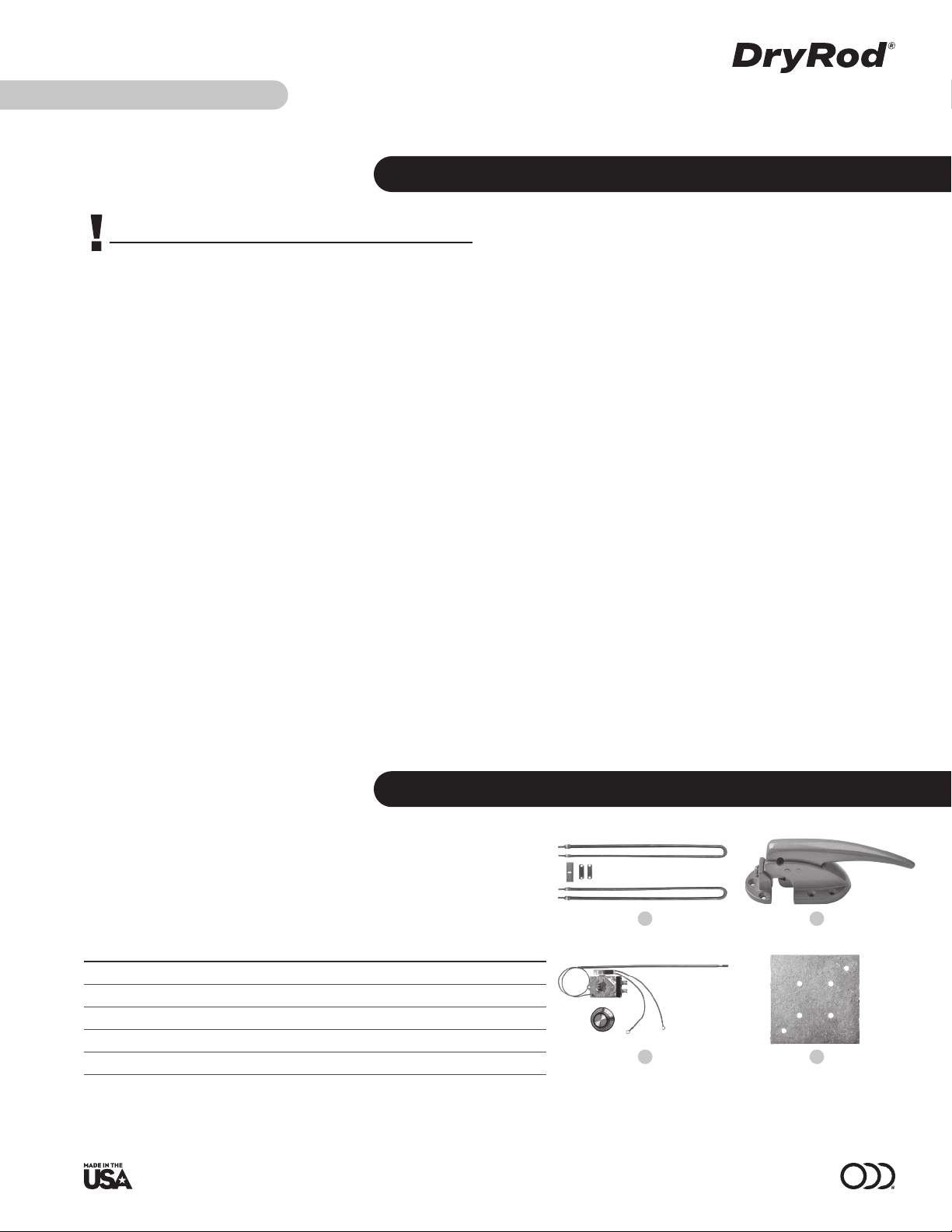
Accessory Note
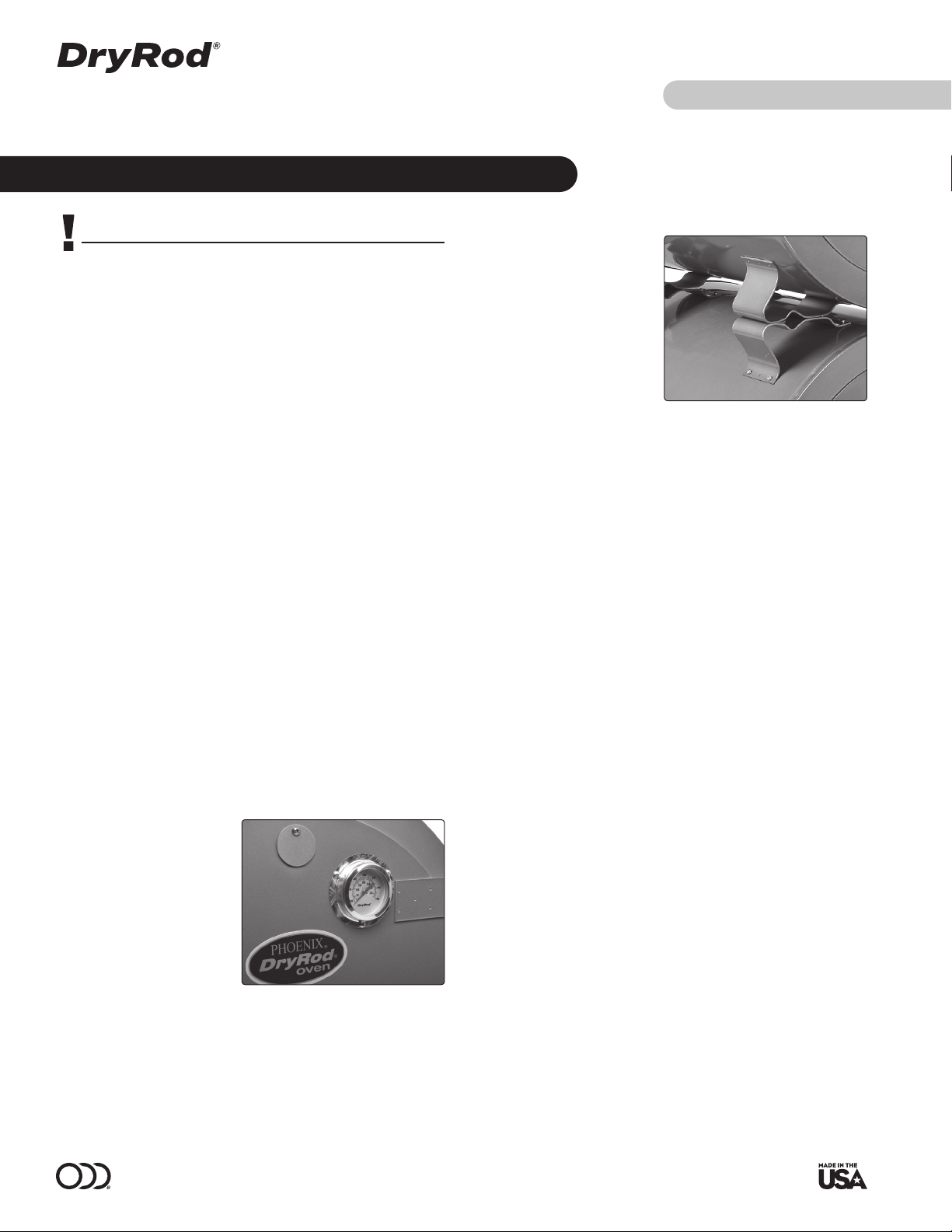
A Door Mounted Thermometer
(part #1250300) is available for
Type 300 Series ovens and can
be easily installed in the field.
Factory installation is available
with original order (see chart on
cover). This thermometer indicates
internal temperature range of
100˚ to 700˚F with an accuracy
specification of +/-10˚. Product
accuracy testing is conducted using
standards traceable to the N.I.S.T.,
USA.
Accessory Note
Stacking provision for Type 300
ovens is available with original
order. Stacking permits two Type
300 ovens to occupy the same floor
space as one. For each stack, only
ONE oven needs to be ordered with
the stacking lugs. Stacking lugs
(factory installed only) on lower
oven bolt to feet of any Type 300
oven, whether in the field or newly
ordered.
Electrode Placement
DryRod ovens have divided shelves to allow storage of more than one group of
electrodes. It is recommended to store different electrodes in separate ovens to
avoid contamination. Spread the electrodes evenly, allowing space over each shelf
for air circulation required to remove excess moisture. The maximum suggested
layer depth on any shelf is 5 inches.
Temperature Settings
Temperature range is 100°F (38°C) to 550°F (288°C). The thermostat dial (at rear of
oven) is calibrated from 100° to 550°F. Obtain required oven temperature setting
by rotating dial to line up desired temperature with indicator light in the thermostat
housing.
The indicator light illuminates only when voltage is being applied to the heating
elements. Momentary rotation past desired temperature setting may be necessary
to activate the indicator light in order to locate it for indexing purposes.
Thermostat is accurate to +/-25°F (14°C) at the sensing bulb; however, temperature
may vary slightly at different areas in the oven chamber because this is a
convection type oven.
At the maximum setting, the actual temperature in portions of the oven near the
heating elements may reach approximately 660°F (349°C).
Temperatures over 550°F (288°C) are not recommended. They may cause oven
damage and/or unacceptably high exterior surface temperatures.
Venting
For normal holding operation, set easily adjustable vent on the door about ¼ of the
way open. For replacement vents, see Replacement Parts section in this manual.
Guide to Storage
Electrodes should be stored according to electrode supplier recommendations.
In the absence of storage information from your electrode manufacturer, please
reference Phoenix's Guide To Electrode and Flux Stabilization for approximate
temperatures, found at www.dryrod.com/guide.
Door mounted thermometer
CAUTION
• To provide continued protection against risk of electrical shock, power
cord must be connected to a properly grounded outlet.
• To avoid damage, never place oven in contact with welding current.
• Store in dry location. Unit not to be exposed to rain or moisture.
Stacking lugs

dryrod.com info@dryrod.com +1 414.973.3400 8711 West Port Avenue Milwaukee, WI 53224 Phoenix International
Type 300 Series Electrode Stabilization Ovens
Operating Instructions Operating Instructions
3
Troubleshooting
Oven Fails To Operate: No Heat,
Overheats
1. If the indicator light does not illuminate, check power supply.
2. Check plug at outer end of power cord and run continuity check on complete
power cord. If defective, replace cord assembly.
3. Check indicator light for continuity. See Repair Parts drawing for access
details. If defective, replace indicator light.
4. Check thermostat. If indicator light illuminates, power is being supplied
through thermostat to heating elements. Turn knob from low to high setting
and return. A definite "snap" should be heard at low temperature end and
indicator light should turn off and on with each "snap" cycle. If "snap" is not
heard and indicator light fails to operate, replace entire thermostat.
5. If thermostat operates satisfactorily, check continuity of dual hairpin style
heating elements at bottom center of oven. Failure of one element will
prevent oven operation on 480 volts. If operating on 120 or 240 volts, failure
of one element will cause very slow heating.
6. If thermostat operates satisfactorily, recalibrate thermostat. (See Checking
Thermostat Calibration section below).
Door Will Not Close Properly
1. Use screwdriver to adjust door latch.
2. If latch is broken, replace with Door Latch and Strike (Part #1252200). (See
Replacement Parts section in this manual).
Checking Thermostat Calibration
Each thermostat is adjusted at the factory and calibrated on precision instruments
to control temperatures accurately. Adjustment or re-calibration is not needed
unless the thermostat has been mishandled in transit or changed or abused while
in service.
To check calibration:
1. Use a high grade mercury thermometer to check temperature. For griddle
control, use a disc type thermocouple. Put a couple drops of oil on griddle
surface plate and place thermocouple disc flat into the oil.
2. Turn the dial of the thermostat to 325° mark.
3. Allow enough time for temperature to stabilize or until several temperature
readings are identical.
To calibrate:
1. Remove knob from dial shaft by pulling knob straight out.
2. With screwdriver, turn screw clockwise to decrease and counterclockwise to
increase temperature. Do not allow dial shaft to turn during this operation. A
¼ turn of the screw equals approximately 35°.
3. Replace knob or control dial.
4. After calibrating, let the appliance operate until the temperature has
stabilized, then recheck to determine if the calibration has been successful.
CAUTION
• When replacing heating elements, always replace both elements. Pairing
of one new element with an old element will cause rapid failure of old
element.
Recommended Spare Parts
For users of large DryRod oven quantities or users not in North America:
For normal daily operation, the following spare parts and quantities are
recommended to have inventoried.
1
2
3
4
Item No. Spare Part Description
Part No.
for
120/240V
Part No.
for
240/480V
Recommended
Quantity
per 10 Ovens
1 Heating Element Kit 1250500 1250600 1
2 Thermostat Kit 1251100 1251200 1
3 Cord Kit 1257120 1257121 1
4 Insulation Block 1252400 1252400 1
5 Door Latch and Strike 1252200 1252200 1

Phoenix International 8711 West Port Avenue Milwaukee, WI 53224 +1 414.973.3400 info@dryrod.com dryrod.com
Type 300 Series Electrode Stabilization Ovens Operating Instructions Operating Instructions
4
Replacement Parts
Ordering Information
To order spare or replacement parts, visit our website: www.dryrod.com. When ordering, please confirm that you are ordering parts for the correct oven.
Item
No. Description Qty
Part No.
120/240V
Part No.
240/480V
1Thermostat Housing 1 2200200 2200200
2 Door Latch and Strike 1 1252200 1252200
3Door Mounted Thermometer Kit 1250300 1250300
Door Mounted Thermometer 1
Mounting Bracket 1
Cover 1
4Heating Element Kit 1250500 1250600
Element 2
Jumper 2
Retainer 1
5Thermostat Kit 1251100 1251200
Thermostat 1
Thermostat Knob 1
6Insulation Block 1 1252400 1252400
7Vent Cover Kit
(includes two vent covers) 1 1257152 1257152
8Shelf Assembly Kit 1255100 1255100
Shelf Assembly 1
Cord Kit 1257120 1257121
Connection Cord 1
Cord Grips (7W-2) 1
Lead Kit 1257123 1257123
Lead 2
Conduit Kit 1257151 1257151
Conduit Box 1
Conduit Box Cover 1
Conduit (½") 1
Conduit Connectors (½") 2

dryrod.com info@dryrod.com +1 414.973.3400 8711 West Port Avenue Milwaukee, WI 53224 Phoenix International
Type 300 Series Electrode Stabilization Ovens
Operating Instructions Operating Instructions
5
Replacement Parts
1
4
Thermostat Housing
2Door Latch and Strike
3Door Mounted
Thermometer Kit
Heating Element Kit
5Thermostat Kit
6Insulation Block
7Vent Cover Kit
8Shelf Assembly Kit

Phoenix International 8711 West Port Avenue Milwaukee, WI 53224 +1 414.973.3400 info@dryrod.com dryrod.com
Type 300 Series Electrode Stabilization Ovens Operating Instructions Operating Instructions
6
N5458100B 06.26.19
Phoenix Ovens International LLC warrants its products against defects in material and workmanship. The company will, at its discretion, repair or replace any properly installed Phoenix International
manufactured product which fails under normal operating conditions within one year from date of receipt. Contact the factory for return authorization before returning the product to Phoenix
International freight prepaid. If our inspection confirms that the product is defective under terms of this warranty, it will be repaired/replaced and returned freight prepaid.
This warranty applies only to products sold by Phoenix International, Inc. and specifically excludes installation or de-installation labor, transportation or equipment of another manufacturer used in
conjunction with Phoenix International products. No other warranty, expressed or implied, exists beyond this warranty declaration.
Phoenix constantly strives to improve its products and therefore reserves the right to change design, materials and specifications without notice.
Warranty
Wiring
Note: Jumper wires must be installed outside of insulation.
Thermometer probe wire (not shown) must be installed outside
of insulation.
CAUTION
• All wiring should be done by a licensed electrician in
accordance with state codes, local codes, and National
Electrical Code (NEC) or International Electric Commission
(IEC) standards.
• Improper installation or use may result in serious injury.
• Always remove oven from power source before
troubleshooting or repairing.
Eliminate expensive rework and protect welding profits!
This guide explains proper storage and oven holding temperatures:
• Recondition/rebake procedures for electrode coatings exposed to moisture are included.
• Remove electrodes from cardboard containers before placing in ovens.
• Electrode coatings should not be exposed to the re-baking temperature without first being reconditioned at a lower temperature. Failure to do so may result
in breakdown of electrode coatings. After re-baking, lower temperature to holding level until reissued.
Download your guide at www.dryrod.com/guide.
jumper
1 of 2
thermal
couple probe
heating
element
pilot light
white
black
green
conduit
box
Guide to Electrode & Flux Stabilization
Wiring Diagram for
Type 300 Series
16C, 120V Model
15D, 240V Model
Wiring Diagram for
Type 300 Series
16C, 240V Model
15D, 480V Model
pilot light heating
element
thermal
couple probe
black
green
white
conduit
box
jumper
2 of 2
variable thermostat variable thermostat
This manual suits for next models
8
Table of contents
Other Phoenix Oven manuals
Popular Oven manuals by other brands

Silvercrest
Silvercrest SGB 1380 B2 operating instructions

Alto-Shaam
Alto-Shaam 767-SK Series Installation, operation and maintenance manual

Sharp
Sharp Microwave Drawer SMD2489ES Operation manual

New World
New World UB45CMBK Operation manual

V-ZUG
V-ZUG EasyCook Series manual

Alto-Shaam
Alto-Shaam Vector VMC-H2 Service manual