Type 15 Series Electrode Stabilization Ovens Operating Instructions Operating Instructions
2
Phoenix International 8711 West Port Avenue Milwaukee, WI 53224 +1 414.973.3400 info@dryrod.com dryrod.com
Product Description
Prior to Use
1. Check for correct power supply cord and plug. Confirm that the voltage
selector switch setting corresponds with the power supply to be used. Unit is
set to 240V when shipped.
2. Verify the oven is empty before heating.
3. Check nameplate for voltage ratings.
4. Check for desired thermometer (if equipped) display units (°F or °C). Unit is
set to °F when shipped. To change to °C, see Temperature Indication section
in this manual.
Power Supply
DryRod®II ovens are designed to run on AC voltage and accept either 120 or 240
volts +/-10%. When power is supplied, the indicator light will illuminate.
DryRod II ovens are supplied with a voltage selector switch to operate on either
120 or 240 AC voltage. Please be sure to set the switch to the proper voltage being
used. Operation outside these voltages will impact oven temperature.
Amp Draw
Ovens operating on 120 AC voltage draw 5 amps. Those operating on 240 AC
voltage draw 2.6 amps.
Power Cords
DryRod II ovens are supplied with a female IEC 320 locking power inlet. This inlet
accepts a male IEC 320 locking power cord to provide a fixed connection. The
secured cord can be removed for replacement by applying pressure to the yellow
tab on top of the locking power
cord.
DryRod II oven power cords are
rated for 100-240 volts. When
connected to a properly grounded
receptacle, these ovens meet the
nationally recognized standards for
which they are marked.
DryRod II ovens are available with a
three blade North American power
cord for 120 volt AC operation. The
ovens are also available with a
European/Schuko plug configuration
for operation on 240 volt AC. (See
Replacement Parts section in this manual for optional power cords. See front page
for standard oven configuration with power cord options.)
Electrode Storage
Type 15 Series ovens will fit two full 50 pound cans of electrodes with additional
secondary storage.
DryRod II ovens are not airtight, and electrodes stored within will start absorbing
ambient moisture as soon as the oven cools. We recommend removal of electrodes
at shift end and storage in suitable larger holding ovens until re-issued.
DryRod II ovens are not to be used for re-baking or re-conditioning contaminated
electrodes. They are designed to accept electrodes in 100% usable condition and to
maintain that condition until consumed at the job site. For optimum stabilization,
oven should be hot when loaded and kept powered as long as electrodes are being
stored.
Temperature Settings
DryRod II ovens utilize a variable thermostat, providing an operating range of 100°-
300°F (38°-149°C) average stabilized load temperatures.
The oven operating temperature is set by rotating the thermostat knob clockwise to
increase the temperature of the unit. To decrease the temperature rotate the knob
counter clockwise. This setting is approximate and may need slight adjustment
once the oven temperature stabilizes.
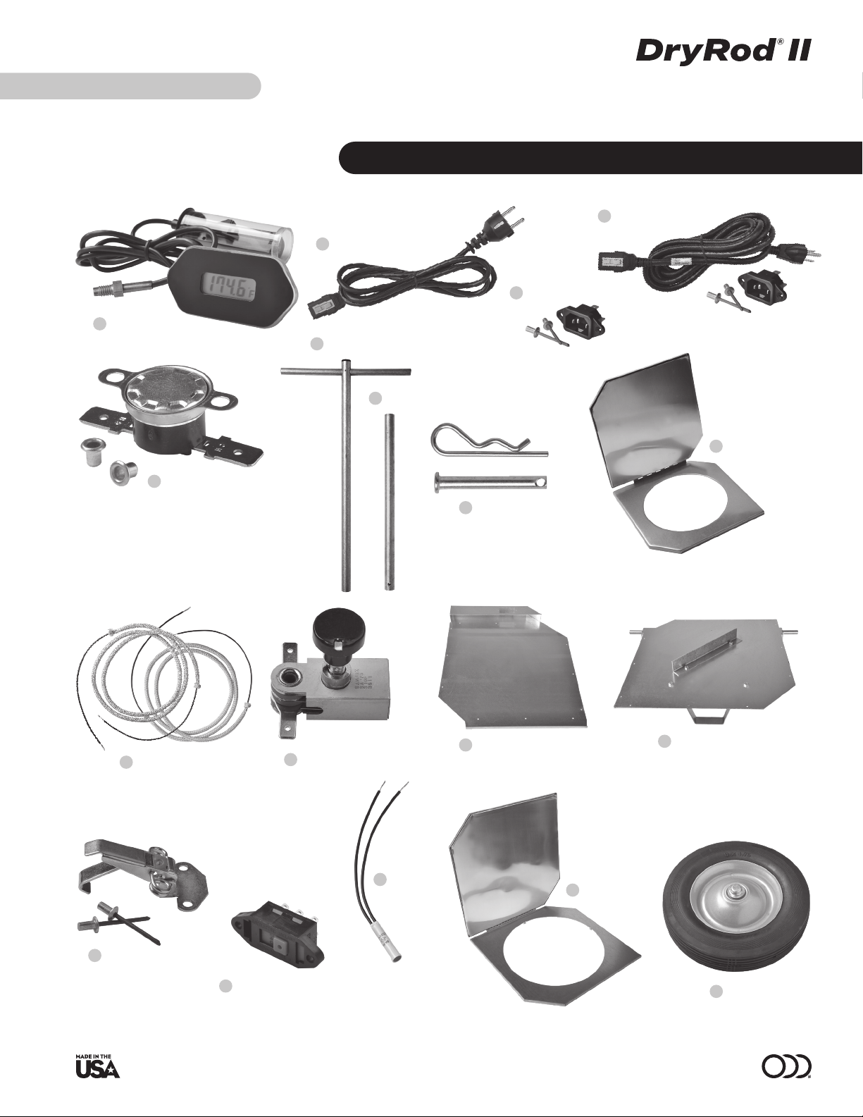
Temperature Indication
DryRod II ovens (part #1205530 and #1205531) are supplied with an optional
battery powered, digital thermometer to indicate the actual temperature inside
oven in either °F or °C.
The thermometers are supplied in °F mode. Conversion to °C mode is accomplished
by pressing the button located in the battery holder. This will cycle between °F and
°C. Thermometers are powered by one AA battery.
Wheels and Retracting Handle
Specific models of the DryRod II ovens (part #1205532 and #1205530) are supplied
with wheels and a retracting handle for easy portability.
The wheels are supplied with a steel hub and ball bearings to withstand wear over
years of service. The handle is supplied with a pin and clip to lock the handle in
either the extended or retracted positions. The retracted position is typically used
for shipping and/or storage of the oven.
Guide to Storage
Electrodes should be stored according to electrode supplier recommendations.
In the absence of storage information from your electrode manufacturer, please
reference Phoenix's Guide To Electrode and Flux Stabilization for approximate
temperatures, found at www.dryrod.com/guide.
Locking power inlet and cord
CAUTION
• To provide continued protection against risk of electrical shock, power
cord must be connected to a properly grounded outlet.
• To avoid damage, never place oven in contact with welding current.
• Store in dry location. Unit not to be exposed to rain or moisture.
• Do not use handles to lift loaded oven. Serious injury may result.