Jobsite CT2142 User manual

30KW INDUSTRIAL DIRECT DIESEL HEATER CT2142
ORIGINAL INSTRUCTIONS
IMPORTANT:
These instructions accompanying the product are the original instructions. This document is
part of the product, keep it for the life of the product passing it on to any subsequent holder of
the product. Read all these instructions before assembling, operating or maintaining this
product.
This product is not suitable for primary heating purposes.
Cannon Tools Limited
Address:20 Station Road, Rowley Regis, West Midlands, B65 0JU.UNITED KINGDOM


1
EC DECLARATION OF CONFORMITY
We CANNON TOOLS LTD
20 Station road, Rowley Regis, West Midlands,B65 0JU.U.K.
Declare that the following machine complies with the appropriate basic safety
and health requirements of the EC Directive based on its design and type, as
brought into circulation by us.
In case of alteration of the machine, not agreed upon by us, this declaration will
lose its validity.
Product description: 30KW INDUSTRIAL DIRECT DIESEL HEATER
Model: CT2142
Applicable EC Directives:
EC Low Voltage Directive 2014/35/EU
EC Directive of Electromagnetic Compatibility 2014/30/EU
ROHS - Directive 2011/65/EU and its amendment Directive (EU) 2015/863
Harmonized standards:
EN 60335-1:2012+A11+A13+A1+A14+A2, EN 60335-2-102:2016
EN 62233:2008,
EN 55014-1:2017, EN 55014-2:2015,
EN 61000-3-3:2013, EN 61000-3-2:2014,
EN 62321-8:2017, EN 62321-2:2014, EN 62321-3-1:2014,
EN 62321-4:2014/A1:2017.EN 62321-5:2014,EN 62321-7-1:2015,
EN 62321-7-2:2017, EN 62321-6:2015,EN 62321-8:2017
20 Station Road, Rowley Regis, West Midlands, B65 0JU.U.K.
Mr. Gurcharan Tony Singh Sanghera
Managing Director
CANNON TOOLS LTD
2020-12-10

2
1. SPECIFICATION
* Based on Gross Calorific Value [Hrs]
Model
CT2142
Heat Input [kW] *
30
Air Flow Rating [m³/h]
750
Fuel Type
Diesel - Kerosene
Fuel consumption [kg/h]
2.4
Voltage [V/Hz]
AC220-240V/50
Air Pressure Setting [bar]
0.31
Current Rating [A]
1.1
Electrical Power [W]
230
Fuse Rating
T3.15A
Dimensions
Net Weight (kg)
22.2
Length (mm)
860
Width (mm)
520
Height (mm)
610
Tank Capacity (L)
34
Operating range (h)
≈12
Standard Accessories
Fuel gauge
yes
Handle
1
Ambient thermostat
built-in
Malfunction detection light
built-in

3
2. IMPORTANT SAFETY INFORMATION
2.1. General Safety Rules
Read instructions carefully. Read and follow all instructions. Place instructions in
a safe place for future reference. Do not allow anyone who has not read these
instructions to assemble, light, adjust or operate the heater.
If the information in this manual is not followed exactly, a fire or explosion may
result causing property damage, personal injury or loss of life.
Service must be performed by a qualified service agency.
Unvented portable heaters use air (oxygen) from the area in which it is used.
Adequate combustion and ventilation air must be provided. Refer to instructions.
Work area safety
•keep work area clean and well lit. Cluttered or dark area invite accidents.
•Do not operate heaters in explosive atmospheres, such as in the presence of
flammable liquids, gas or dust. Heaters create sparks which may ignite the dust
or fumes.
•Keep children and bystanders away while operating a heater. Distractions can
cause you to lose control.
Electrical safety
•heaters plugs must match the outlet. Never modify the plug in any way. Do not
use any adapter plugs with earthed (grounded) heaters. Unmodified plugs and
matching outlets will reduce risk of electric shock.
•Avoid body contract with earthed or grounded surface such as pipes, radiators,
ranges and refrigerators, there is an increased risk of electric shock if your body
is earthed or grounded.
•Do not abuse the cord. Never use the cord for carrying. Pulling or unplugging
the heater. Keep cord away from heat, oil, sharp edges or moving parts.
Damaged or entangled cords increase the risk of electric shock.
•When operating a heater outdoors, use an extension cord suitable for outdoor
use. Use of a cord suitable for outdoor use reduces the risk of electric shock.
Personal safety
•Stay alert, watch what you are doing and use common sense when operating

4
a heater. Do not use a heater while you are tired or under the influence of drugs,
alcohol or medication. A moment of inattention while operating heaters may
result in serious personal injuries.
•Prevent unintentional starting. Ensure the switch is in the off position before
connecting to power source.
•Remove any adjusting key or wrench before turning the heater on. A wrench or
a key left attached to a rotating part of the heater may result in personal injury.
•Dress properly. Do not wear loose clothing or jewellery. Keep your hair,
clothing and gloves away from moving parts. Loose clothes, jewellery or long hair
can get sucked into the in moving parts of the heater.
Heater use and care
•DO NOT move the heater when it is in operation or when plugged into the
mains supply. Only move heater once it has cooled and it has been unplugged.
•Use the correct heater for your application. The correct heater will do the job
better and safer at the rate for which it was designed.
•Do not use the heater if the switch does not turn in on and off. Any heater that
cannot be controlled with the switch is dangerous and must be repaired.
•Disconnect the plug from the power source before making any adjustments.
Such preventive safety measures reduce the risk of starting the heater
accidentally.
•Store idle heater out of the reach of children and do not allow persons
unfamiliar with the heater or these instructions to operate the power tool. Heaters
are dangerous in the hands of untrained users.
•Maintain heaters. Check for misalignment or binding of moving parts,
breakage of parts and any other condition that may affect the heaters operation.
If damaged, have the heater repaired before use. Many accidents are caused by
poorly maintained heaters.
•Use the heater, in accordance with these instructions, taking into account the
working conditions and the work to be performed. Use of the heater for
operations different from those intended could result in a hazardous situation.

5
WARNING
Do not store or use gasoline or other flammable vapors and liquids in the vicinity
of this or any other appliance.
WARNING
Fire, burn, inhalation, and explosion hazard. Keep solid combustibles,
such as building materials, paper or cardboard, a safe distance away from
the heater as recommended by the instructions. Never use the heater in
spaces which do or may contain volatile or airborne combustibles, or
products such as gasoline, solvents, paint thinner, dust particles or
unknown chemicals.
WARNING
Direct-fired heaters may cause carbon monoxide (co) poisoning when
incorrectly used, e.g indoors without adequate air circulation, or if not
properly working. Co poisoning may lead to death.
GENERAL HAZARD WARNING
Failure to comply with the precautions and instructions provided with this
heater, can result in death, serious bodily injury and property loss or
damage from hazards of fire, explosion, burn, asphyxiation, carbon
monoxide poisoning, and/or electrical shock. Only persons who can
understand and follow the instructions should use or service this heater. If
you need assistance or heater information such as an instructions manual,
labels, etc. Contact the manufacturer.
WARNING
Not for home or recreational vehicle use
WARNING
Your safety is important to you and to others,
So please read these instructions before you operate this heater

6
The electrical system to which the appliance is connected must comply with
current legislation. Installation requires a residual current circuit breaker
(rccb) in the main electrical distribution board.
Unplug the appliance before performing any maintenance operations.
Always check the power cable before using the appliance. It must not be
bent, taut, stretched, crushed or any way damaged.
The power cable must be replaced by qualified personnel only. Use an
original power cable only with a 3-pin approved plug.
The front outlet is very hot during operation. Do not touch! Burn danger.
ELECTRICITY SUPPLY
This range of heaters is designed to run off 220‐240V 50Hz electrical supply.
WARNING: This appliance must be earthed.
Note: If the Plug needs to be replaced to suit local requirements a qualified
electrician should carry out the replacement taking care to earth the unit and
maintain the correct phase connection as per the wiring diagram.
FUEL SUPPLY
Please only use the following fuel types in the heater: Kerosene or Diesel with
viscosity t.
WARNING: Under no circumstances should any other fuel type be used. Do not
fill the fuel tank while the heater is running.

7
3. TECHNICAL DESCRIPTION
Extract the heater from its carton. If the unit is anyhow damaged, do not use it
and contact your dealer.
Pos.
Description
Qty
A
Handle
1
B
Plain washer ø6
4
C
Clamping screw
4
D
Wheel
2
E
wheel shaft
1
F
Plain washer ø12
2
G
Nut M12
2
H
wheel cover
2
I
Cotter
2
J
caster fixing plate
2

8
4. INSTALLATION INSTRUCTIONS
4.1 Assembling
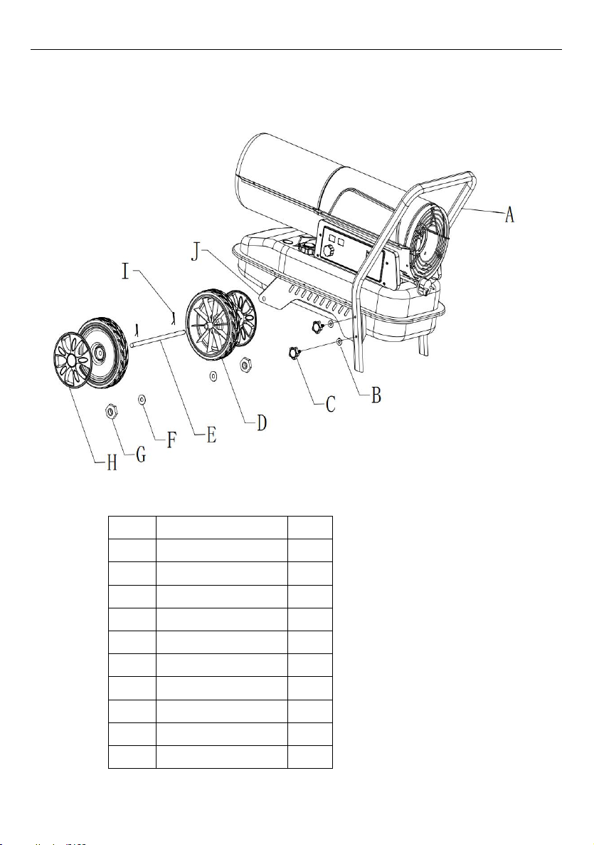
To assemble the heater, proceed as follows
1. Insert the wheel shaft E into the corresponding hole of the caster fixing plate J,
insert the cotter I to the corresponding holes of the wheel shaft; put plain washer
F to the two sides of shaft, slide the wheel D over the wheel shaft E, screw the
nut G to fix the wheel on the shaft,Install the wheel cover H.
2. Use the clamping screw C and Plain washer ø6 B to install the Handle A into
the corresponding hole of the caster fixing plate J.
4.2 Installation
Position the heater on a flat, level, non-flammable, solid surface.
Direct-fired heaters are intended for use in outdoor open areas or in
indoor well ventilated areas. For indoor use, provide permanent ventilation
openings of at least 25 cm²/kW, equally distributed between floor and high level,
with a minimum of 250 cm².
● Only install the heater in normal upright position.
● Do not place the heater near walls, corners or low ceilings.
● Do not place the heater below a socket outlet.
● Do not place the heater on moving vehicles or where it can tip over.
● Keep the heater away from flammable, combustible, explosive or corrosive
materials.
● Keep the heater away from curtains or similar materials that could block the air
inlet and outlet.
● Never block or restrict the air inlet and outlet for any reason.
● Keep the power cable away from heat sources, sharp edges, cutting and
moving parts.
● Do not expose directly to the weather or to excessive humidity.
● Do not place the heater in the immediate surroundings of a bath, shower or
swimming pool.
● Follow general and special fire safety regulations in force in all fields of
applications. In any case ensure the following minimum safety clearances from
materials or objects in the surroundings of the heater:
Side: 0.6 m
Air inlet side: 1 m
Top: 1.5 m
Hot air outlet side: 3 m
Floor: 0 m
Minimum Opening Size
800 cm²

9
● Floors and ceilings must be made of fireproof materials in the place where the
heater is operated.
● Do not connect direct-fired heaters to air ducts.
4.3 Instructions for Use
4.3.1 Start-up
Fill tank with clean fuel. Only use Diesel or Kerosene.
The fuel gauge on top of the tank allows to check fuel level
Connect the power cord plug to a AC220-240V 50 Hz earthed electrical supply
system.
Earthing is mandatory.
When complete “start-up” above, the left display window shows “--”, the right
display window shows ambient temperature value.
Push the power switch to “ON”(1) position.
The default temperature setting is 20℃, be showed on the left display window.
If the ambient temperature is lower than default temperature, the electrodes start
sparking, after 7 seconds, the heater starts.
If the ambient temperature is higher than default temperature, turn thermostat
control knob to desired temperature, the electrodes start sparking, after 7
seconds, the heater starts.
COLD START-UP: at low temperature keep the air vent hole closed by a finger
during ignition to make start-up easier.
ABNORMAL OPERATION: in case of malfunction (flame failure, reduced air flow,
bad combustion, etc.) the heater stops and the indicator light starts FLASHING
(THE LOCK-OUT MODE code will be showed on the display window).
4.3.2 Manual reset/restart
If the heater is in lock-out mode, check and remove the cause of lock-out before
restarting the heater. To reset, turn the ON/OFF switch to 0 and then again to I. In
case of repeated malfunction, call technical service. Turning the thermostat
control knob will NOT reset the heater.

10
4.3.3 Shut-down
Move switch to "OFF" (O) position. Unplug the unit when not used for a long
time.
Never disconnect the heater from mains to stop it while in operation.
Always allow the cooling sequence to be completed (BGO1601-50), otherwise
the residual heat could damage internal components.
Do not cover the heater. Do not block the air inlet and outlet.
The heater outlet is very hot during operation and after use. Do not touch!
Use personal protecting equipment if needed.
Children should be supervised to ensure that they do not play with the
appliance.
The appliance is not intended for use by persons (including children) with
reduced physical, sensory or mental capabilities, or lack of experience and
knowledge.
Unplug the heater before moving it. Never pull the cable to unplug or
move the unit.
Do not leave the heater unattended when in use.
Never use the appliance with wet hands or when either the heater or the
power cable is wet.
If the supply cable is damaged, it must be replaced by the manufacturer,
by a service agent or a similar qualified person.
5. CLEANING, MAINTENANCE AND STORAGE
Regularly wipe the enclosure using a soft sponge or cloth. For very dirty parts,
use a sponge wetted with lukewarm water and a mild detergent, then dry using a
clean cloth.
Keep air inlet and fan free from dust and dirt. To clean inner parts, gently blow
compressed air through air inlet.
Regularly inspect the power cable: if worn, cracked or damaged have it replaced
by technical service.
Before storing the heater, make sure it is perfectly cool and dry. Cover the unit
with a plastic bag, put it in its packing box and store it in a dry, ventilated place.
Before starting any maintenance task, shut down, unplug and let the
heater cool down for at least 15 minutes.
Do not attempt any electrical repair yourself. If the heater needs
service or repair, contact a qualified technician.

11
Do not use a faulty unit unless a qualified technician has inspected and
repaired it.
When cleaning, make sure that water does not enter the unit.
Do not open the enclosure to clean the inner parts. Do not spray water
into the heater.
Never use solvents, gasoline, toluene and similar aggressive
chemicals to clean the heater.
The following checks BY QUALIFIED PERSONNEL ONLY are recommended
before every seasonal use:
Nozzle
Carefully unscrew nozzle from nozzle fitting. Blow compressed air through
nozzle orifice to free it from dirt. Replace nozzle if necessary.
Air Filters
Clean air filters. Remove filter end cover (11), wash air intake filter (10) using a
light detergent and dry it thoroughly before re-installing. Replace air delivery filter
(9) once a year.
Ignition Electrodes
Clean, adjust and if necessary replace ignition electrode. For electrode gaps see
Fig. following (dimensions in mm).

12
Compressor Pressure Adjustment
The compressor pressure is factory set and must be checked and
adjusted by qualified technicians only. Tampering with the unit may be
dangerous.
Remove pressure gauge cap. Connect a pressure gauge on the pressure
measuring port on the rear guard. Start heater and read air pressure value. If
necessary adjust pressure to the correct value turning the adjusting screw (the
air vent hole in the adjusting screw middle) clockwise to increase, anticlockwise
to decrease the pressure:
Electrical
Inspect cables, electrical parts and connections.
Model
Air Pressure (bar)
CT2142
0.31

13
6. WIRING DIAGRAM

14
7. TROUBLESHOOTING
PROBLEM
CAUSE
REMEDY
Motor does not
start
E1 displayed on the
screen
No power or low voltage
Check power line and voltage
Check fuse and replace if necessary
Faulty or damaged power cord
Check and replace if needed
Faulty motor/capacitor
Check and if necessary replace
Lock-out of appliance due to
previous overheating
Detect the cause of overheating
Shut the appliance down
Check air inlet and outlet
Wait some minutes and restart the
appliance
E2 displayed on the
screen
The temperature probe is faulted or
the connector for temperature
probe is loosen
Check and replace if the temperature
probe if needed
Check and replace the PCB if needed
Motor runs, but
the heater does
not ignite and
locks out after a
short time
E1 displayed on the
screen
Empty fuel tank, dirty or wrong fuel
Remove wrong or dirty fuel
Fill the tank with clean Diesel or
kerosene
Fuel filter clogged
Clean or replace fuel filter
Air leaks in oil line
Check hoses, tighten connections, if
necessary replace
Burner nozzle clogged
Clean nozzle blowing compressed air,
replace if necessary
Fuel viscosity increased at low
temperature
Mix Diesel with 10-20% kerosene
Flames come
out of flue outlet
E1 displayed on the
screen
Insufficient airflow into combustion
chamber
Check air inlet, fan, motor
Compressor pressure too high
Check air pressure, adjust if needed*
Heater stops
during operation
Ambient
temperature
displayed on the
screen
The room temperature set on room
thermostat has been reached
Normal operation
To start turn the temperature control
knob clockwise on a higher setting
Heater stops
during operation
E1 displayed on the
screen
Flame failure
Check and remove the cause(s) of
malfunction
To reset, turn On/Off switch to 0 and
then to I
Call technical service if the problem
persists
Bad combustion
Reduced airflow
Overheating
LC displayed on
the screen
Failed 3 times for igniting will lock t
he PCB and stop working
With electricity on, it will be unlocked
after 3 times power switch to ON in 1
0 seconds;

15
8. DISPOSAL GUIDELINES
Do not dispose of this product with general household waste.
This product must be disposed according to the laws governing
Waste Electrical and Electronic Equipment.
If required, contact your local authorities for information regarding
the available disposal facilities.
9. SYMBOLS
The following symbols are used in this manual and/or on the machine:
Denotes risk of personal
injury or damage to the
tool
WARNING – To
reduce the risk of
injury, user must read
“instruction manual”
In accordance with
essential safety
standards of applicable
European directives
Mandatory use of eye
protection
Wear noise protection

16
10. ENERGY EFFICIENCY TABLE
Model identifier(s): CT2142
Indirect heating functionality: [no]
Direct heat output: 30(kW)
Indirect heat output: N/A (kW)
Fuel
Space heating emissions (*)
NOx
Select fuel type
[liquid]
Kerosene
69[mg/ kWhinput] (GCV)
Item
Symbol
Value
Uni
t
Item
Symbol
Valu
e
Unit
Heat output
Useful efficiency (NCV)
Nominal heat
output
Pnom
30
kW
Useful efficiency at
nominal heat output
ηth,no
m
100
%
Minimumheat
output
(indicative)
Pmin
N/A
kW
Useful efficiency at
minimum
heat output (indicative)
ηth,min
N/A
%
Auxiliary electricity consumption
Type of heat output/room temperature control
(select one)
At nominal heat
output
elmax
0.002
kW
Single stage heat output, no room
temperature control
[no]
At minimum
heat
output
elmin
N/A
kW
Two or more manual stages, no room
temperature control
[no]
In standby mode
elSB
N/A
kW
with mechanic thermostat room
temperature control
[no]
with electronic room temperature
control
[yes]
with electronic room temperature
control plus day timer
[no]
with electronic room temperature
control plus
week timer
[no]
Other control options (multiple selections
possible)
room temperature control, with presence
detection
[no]

17
Room temperature
control, with open
window
detection
[no]
with distance control
option
[no]
with adaptive start
control
[no]
with working time
limitation
[no]
with black bulb sensor
[no]
Permanent pilot flame power
requirement
Pilot flame
power
requirement (if
applicable)
Ppilot
0
kW
(*) NOx = nitrogen oxides
The seasonal space heating energy efficiency ηS
Item
Symbol
Value
Unit
The seasonal space
heating Energy
efficiency in active
mode
ηS,on
100
%
Correction factor (F1)
/
0
%
Correction factor (F2)
/
7
%
Correction factor (F3)
/
0
%
Correction factor (F4)
/
0
%
Correction factor (F5)
/
0
%
Biomass label factor
BLF
1
/
The seasonal space
heating energy
efficiency ηS
ηS
97
%
Energy efficiency
classes
A

18
11. EXPLODED VIEW
Table of contents
Other Jobsite Heater manuals
Popular Heater manuals by other brands

Acova
Acova Regatta twist air ec 594w coul Instructions for use

HotWire
HotWire V1 installation manual

GVA
GVA GVAOR7F instruction manual

Norseman
Norseman XB Series Installation, operation & maintenance instructions

Ingersoll-Rand
Ingersoll-Rand HEATER 420 Operator's manual

Orbegozo
Orbegozo BP 0303 A instruction manual