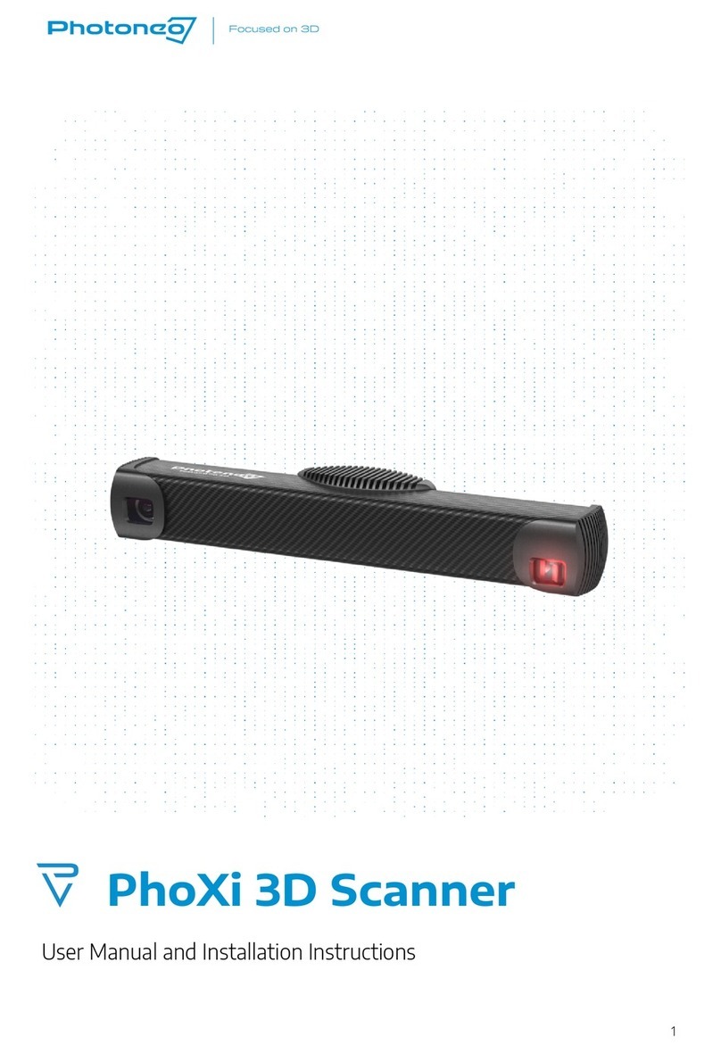
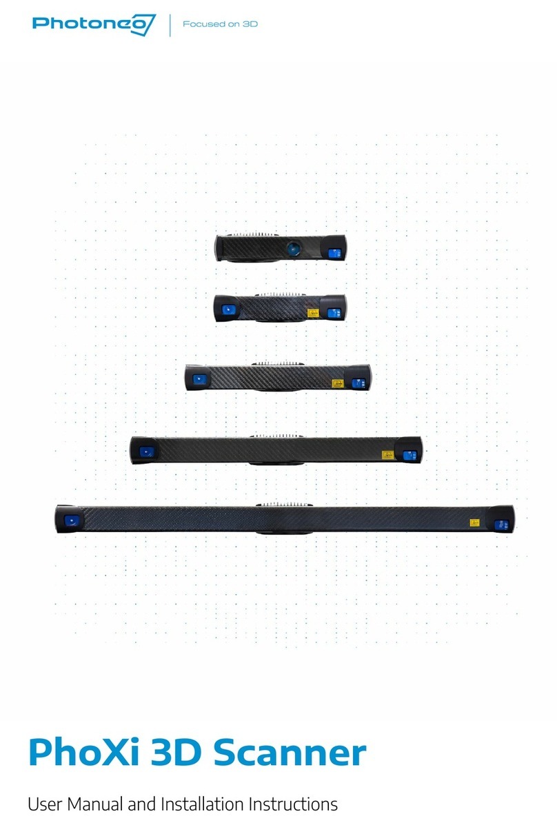
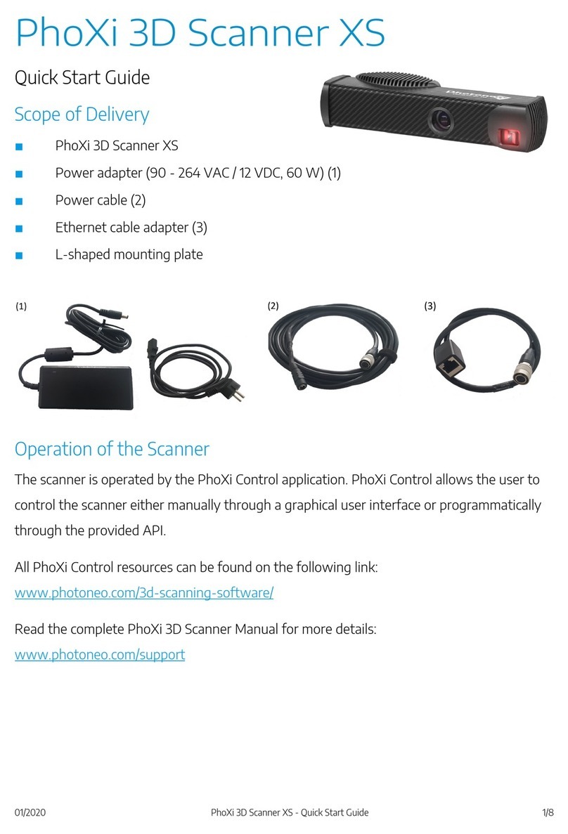
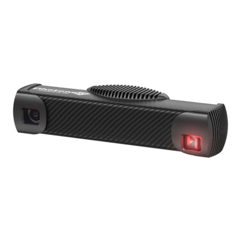
Photoneo PhoXi User manual

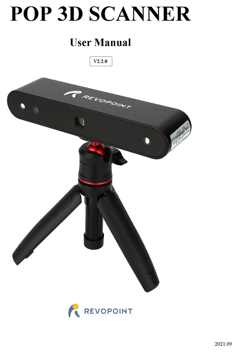
PhoXi 3D Scanner
Instruction manual
For PhoXi 3D Scanner and PhoXi Control Application
(Firmware version 1.1.12)
Thank you for purchasing Photoneo PhoXi 3D Scanner!
The Photoneo PhoXi 3D Scanner is a compact yet powerful 3D scanner with unbeatable performance in the
terms of precision, noise and overall efficiency. It can be used for scanning a wide variety of subjects in
various configurations, making it an universal tool for all kind of industrial applications. The scanner is
controlled by a supplied software - PhoXi Control Application - that provides both a GUI and an API.
The contents in this manual are based on firmware version 1.1.4 for this scanner. Visit the Photoneo website
for the latest information.
Please read this instruction manual before use.

Safety instructions
Photoneo PhoXi 3D Scanner is a Class 3R laser product. Do not deliberately look or stare into the laser
beam. Laser protective eyewear is normally not necessary, but recommended. Handle the product carefully
and follow all necessary safety instructions.
This device contains laser. Please follow the necessary safety instructions.
Warning: This device is Laser class 3R product. Do not look
into direct laser light! Use of protective eye glasses is
recommended.
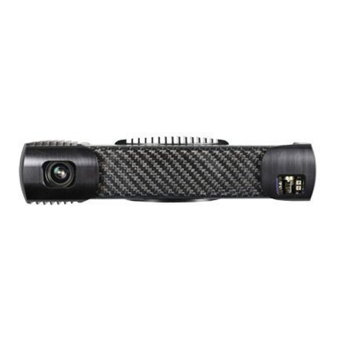
The laser projector aperture is located at the right side of the
front panel of the device, as shown on the picture. The
aperture is clearly marked by a warning label. Do not look
into laser projector unit while the device is in use.
Information according to IEC / EN 60825-1 (2014):
Wavelength: 639 nm
Peak / CW Power: 314 uW
Pulse Energy: 382 nJ
Pulse Length: 960 us
Do not remove the labels affixed to the product. Do not open or disassemble the product. Always follow the
instructions in this user guide. Caution - Use of controls or adjustments or performance of procedures
other than those specified herein may result in hazardous radiation exposure .

Assembly and installation
● Mount the scanner to the desired position
● Connect the scanner to the computer or local network via ethernet cable
● Plug the scanner into the power outlet (AC adapter is included in the shipment)
● Download PhoXi Control Application from the Photoneo website
https://www.photoneo.com/download/ and install it
● Run the PhoXi Control Application and try to make your first scan
○ after the start, the application list all scanners found in the network
○ doubleclick on the scanner to establish a connection, new window is open
○ click the button SoftTrig to make the first scan
● Please read this manual for further information and tips how to achieve best quality scans.
Contact
Jamnického 3, 841 05 Bratislava, Slovakia
Technical support
Copyright © 2016 Photoneo s.r.o

PhoXi Control Application
Introduction
PhoXi Control Application enables user to control PhoXi 3D Scanner manually through GUI or
programmatically through provided API.
All communication between the control application and the scanner is carried out over the Ethernet.
One application can establish connections to multiple scanners at once, but one scanner can have only one
active connection with the control application at a time.
The main use of the GUI is in setting up the scanning environment, configuring the advanced scanner
parameters and testing out the output. Furthermore, the GUI can be used as a powerful debugging tool for
developing with the API, because calls to the API trigger the same response in the GUI as the user input.
After triggering the scan by calling the API method, the application will execute the scan, send it as the
output of the call and displays it simultaneously in the GUI.
The API was designed to be a central platform for building custom industry applications for PhoXi 3D
Scanners. To facilitate the development process and reduce computing resources, all the computations are
performed on the device.
Graphical User Interface
Overview
The main window of the application is called Network Discovery and displays the list of all PhoXi 3D
scanners available on the network. After choosing the scanner to work with, new Scanner window is open for
that particular scanner. Windows can be organised by dragging the title of the window like in standard
windows applications.
In Windows OS, the application minimizes to system tray. To close the application, use the Menu or right
click on the tray icon and choose turning off the application.
Network Discovery window

Listing scanners
Network Discovery window list all available scanners on the network. After the application starts, please wait
a moment until all scanners are found.
In the case your scanner is not listed, please make sure that your scanner is turned on and connected to the
network. Then click Refresh button and wait for the scanner to appear in the list.
Connecting to the scanner
To start controlling the scanner, double click on the scanner in the list or select the scanner and click
Connect. Application will connect to the scanner and open Scanner window. For the other users on the
network, the status of the scanner will change from Ready to Occupied. Therefore when you share the
scanner with multiple users, make sure you disconnect from the scanner when not in use.
Configuring the scanner network settings
To switch between static and dynamic IP of the scanner in the network, select the scanner in the list and
click the button Configure . Use the DHCP for dynamic IP allocation or Static IP for manual configuration.
Scanner window
Scanner window consists of 3 parts: Main Controls, Settings pane and a Viewer pane.
TIP: After the window opens, hit F5 or button SoftTrig to trigger the scan.
Main Controls
Control
Explanation
Pause
Pauses the acquisition mode (useful in FreeRun mode)
Stop
Safely stops the acquisition mode before disconnection

Logout
Disconnect from the scanner
SoftTrig
Trigger new scan and display the pointcloud
Mode
- SoftwareTrigger
- FreeRun
Software trigger - single scan is triggered manually
FreeRun - the device is scanning consecutively until you press pause or
stop button
SavePointCloud
Saves current point cloud to the file. Supported formats:
- Standford’s PLY
- Leica’s PTS
- Photoneo RAW data format (*.praw)
- Expanded Photoneo RAW data format (*.prawf)
- Raw images in tif
Use “RecordingOptions” to define which data you want to save.
TestSpeed
Tests the speed of the connection to the device
RecordingOptions
Use “Options” button next to the file format to set which data will be stored
when saving the point cloud in this file format. This settings are applied
when saving the data by “SavePointCloud” button and also in recording
mode.
When checkbox on the left (next to the name of file format) is checked, then
the point cloud is stored in this file format in recording mode. You can check
multiple file formats.
Record
Starts recording mode. Every captured point cloud is saved in the directory
and file formats specified in “RecordingOptions”.
FirmwareUpdate
Starts the process of updating the firmware on the device.
Settings pane
This pane displays settings that are stored locally in the scanner and are used to configure the scanning and
output process.
Controls

● Button Set - sets the properties of the scanning process. When the checkbox SaveOnSet is
checked, the settings are written to the scanner memory. Otherwise the settings will be used only for
the current session and remain until the scanner is disconnected.
● Button Refresh - retrieves actual settings from the scanner memory.
Settings are divided into two groups:
●Properties - settings that affect the scanning process
●Output structure - settings that affect which output properties of the computation are retrieved with
the scan
Properties settings
Setting
Explanation
ShutterMultiplier
controls the shutter of the camera in multiplies of the base scan time (integer value,
1-8)
Confidence
controls the amount of output points based on point reliability. This enables the user to
set preference based on the application. Some applications require a more complete
output at the expense of lower precision. Other applications are meant to work with
precise data only and need to filter out regions where the precision does not meet a
certain threshold
ScanMultiplier
The device will perform multiple scans and aggregate the result to achieve a better
precision and a more complete coverage.
Coordinates
you can change Coordinate space (markers space, camera space,...)
Output structure
Use the checkboxes to select which kind of data will be retrieved from the scanner. You can speed up the
retrieval time by selecting only the data needed for your application.

Viewer pane
This pane displays the output from the scanner. After the start of the application, hit F5 or the button
SoftTrig in main controls to trigger the scan. The output is provided in different formats that can be switched
by the tabs at the bottom. Each view has its own settings on the right.
Tab 3D Viewer
Use this tab to get general overview about the scanned scene. It shows the output in a point cloud with
grayscaled texture.
Settings
Show Normals
Renders normal vectors of planes given by central point and neighbouring
points. The number of neighbouring points in is given by Normals
distribution setting.
Normals distribution
Determine how many points will be used to compute normal vectors in
central points. Distribution 1 means every point has own normal vector.
Normals length
The size of rendered normals.
Axis
Renders axis of the coordinate system.
Laser&Camera View
Renders the position and field of view of camera and laser
Texture Multiplier
Multiplies the point color intensity by given number.

Controls
Left mouse button drag
Rotate the point cloud around the selected point of focus. By
default, selected point of focus is the camera position
Mouse wheel or
vertical right mouse button drag
Zoom in/out
Mouse wheel drag or
Hold SHIFT + left mouse drag
Move the point cloud
Hold CTRL + left mouse drag
Tilt the point cloud
F
Set the point of focus to the point under the mouse cursor. This is
the point the scene is rotated around.
R
Changes the view so that the cloud point is visible.
+
Increase the size of point
-
Decrease the size of point
Tab Confidence Map
This tab displays the expected deviation of the measured distance. This means, the darker parts are
scanned with lower error. The light areas indicate where the error might be higher. These areas might
indicate problematic parts of the scene.
Tab Depth Map
This view shows the scene as a grayscaled image, where the color intensity of every pixel represents the
distance of the measured point from the camera. The depth value of the pixel under the cursor is shown in
the bottom of the window. To improve the visual readability of the image, adjust the settings on the right side
of the window as explained below. This view can be used also for measuring the distance from one pixel to
the other by drawing a line between them with the right mouse button.
Settings
Min value
Minimal depth of the point. Points with lower depth are depicted black.
Max value
Maximal depth of the point. Points with higher depth are depicted white.
Multiplier
The depth value of the point is multiplied with this constant.
The default setting for Min and Max value is 0 - 255 (the standard range for color intensity). However, many
points may be much further than 255 mm, making the image look mostly white. In this case you may want to
increase the Max value above the depth value of the furthest point.
Controls
Left mouse button drag
Move the scene
Mouse wheel
Zoom in/out
Right mouse button drag
Draw a line and compute distance. The distance is shown on the

top of the viewer pane.
Tab Texture
Shows the same view as the Depth Map tab, but with the applied grayscaled texture.
API
Introduction
The PhoXi API provides all the building blocks for developing your custom application for PhoXi 3D Scanner.
The API is provided directly by PhoXi Control Application, so make sure the application is running before
using the API.
This manual will demonstrate how to use the API on two examples. You may start the development based on
one of the examples and modify it to suit your specific needs. We will use Microsoft Visual Studio 2013 and
CMake to depict how to run the examples.
The technical documentation is located in the file API/API_Manual.html inside the application installation
directory. On Windows OS, the path to the API directory is usually
“Program Files/PhotoneoPhoXiControl/API”.
Getting started example - “Connect and Grab”
This example will test that everything is working correctly and that you are able to use the API. It will also
demonstrates that the GUI is a powerful debugging tool as it displays the responses of API calls in real time.
The flow of the program is as follows:
- Firstly, it tests that the PhoXi Control Application is running
- Then it will get the list of all devices available on the network
- If you have already opened some device in PhoXi Control Application, it will connect to that device.
Otherwise it will connect to the last scanner in the list.
- It will execute 5 single scans by manual trigger and 5 scans in the free run mode.
For the details, please see the source code and consult the technical documentation. Also note that this
example only illustrates the basic usage without any extensive checks for unexpected conditions.
Instructions to run the example
- Copy the content of the directory API/examples/cpp/ConnectAndGrab_CPP to your custom
directory. (This is only necessary when you want to edit the source code. Originally, the source code
is located inside the Program Files directory, so you will need admin rights to change the file.)
- Launch CMake
- Choose the source and destination directory
- Click Configure button, specify Visual Studio 2013 as the generator for the project and
confirm by Finish button
- Wait while the configuration is done, then click Generate button
- In the destination directory, open the file ConnectAndGrab.sln
- Rebuild the solution in Visual Studio (menu > Build > Rebuild Solution).
- Set the project ConnectAndGrab as a StartUp Project in the right context menu.
- Make sure that PhoXi Control Application is running
- In Visual Studio, hit F5 to run the example (menu > Debug > Start Debugging)
- While the example is running, switch back to the PhoXi Control Application - every frame that the
camera captures is displayed in the Viewer pane.
Full API example
This example illustrates the use of the API in a production environment where every possible error condition
should be handled carefully. To run the example, please follow the instructions from the previous example.
The source code is located in API/examples/cpp/FullAPIExample_CPP .
This example shows how to:
- find available scanners on the network
- connect to the scanner using hardware identification number, index in the list or to the first active
device
- get the details about current device state and capabilities
- capture the scene in freerun or manual mode and get the output in all provided formats
- change the scanning settings and specify the desired output formats
- handle and store received data
- correctly disconnect the device
Please consult the source code and technical documentation for more details.

Quick scanning guide
How to configure the scanner to provide the best quality
The quality of the scan depends on multiple factors. The scanner provides a variety of settings to enable an
optimal scan; however, even by rearranging the positions of the scene and scanner you can get better
results. Always arrange the scene to have the best conditions for scan first and only then manipulate the
settings of the scanner.
Distance: Closer objects have a better spatial resolution and generally less noise.
Material albedo (reflectivity): A material with higher albedo provides a better signal-to-noise ratio.
Strong ambient light: Indoor ambient light generally does not influence the scan. However, very strong light
such as direct sun might be a problem. This occurs especially when scanning outdoors. Try to remove all
sun illumination e.g. by shadowing the window, or by moving into a different place.
Reflections: Generally, non-glossy, matte materials are scanned without problem. Even soft-gloss objects
have a nearly optimal scan. However, any specular reflections might influence the scan quality since the
projected light is reflected out of the sight of the camera (in which case that part has a poor quality), or when
reflected into other parts of the scene, reflected light interferes with scanning (in which case the part
illuminated by reflection has artifacts). Especially metal with high-gloss finish (mirror-like) is problematic.
As a rule of thumb: Take a flat piece of the material and try to look at it as it is a mirror. If you are able to
recognize a shape of your head as reflected by the material, the material is glossy. Depending on the scene,
some parts might be not scanned optimally.
When scanning glossy objects, find a position where light coming from the projection unit does not illuminate
other objects on the scene.
To further increase change of optimal scan while scanning glossy materials, use the
“AmbienLightSuppresion” setting. Using this setting will increase the scanning time.
Transparent objects: It is not possible to scan transparent materials such as glass, ice or water. Remove
such materials from the scene to avoid artifacts. A thin layer of plastic wrap would still allow the wrapped
object to be scanned with the risk of greater noise. It might also increase the glossiness of the object (see
previous paragraph). Scanning through a window is possible as long as the window does not cause
reflection -- the angle between projector unit and window should be close to a right angle.
Translucent objects: It is possible to scan translucent objects to some extent. Scattering of the light inside
the material might cause the object surface to be scanned with a lower precision. For materials of a high
degree of translucency the same applies as for the transparent objects.
Assessing the quality of the scan
First, do a quick visual check of the scan in Control Application. Switch to the Point Cloud tab. Do you see all
parts of the object? Use the mouse drag to rotate the scene or mouse wheel to zoom in or out.
For more advanced assesment, switch to the ConfidenceMap. This tab displays the expected deviation of
the measured distance. This means, the darker parts are scanned with lower error. The light areas indicate
where the error might be higher. These areas might indicate problematic parts of the scene.

Problems and Troubleshooting
Problem: I don’t see PhoXi Scanner listed in PhoXi Control Application
● Double check all cable connections
● The Firewall blocks Bonjour Discovery Service (process mDNSResponder .exe) - Turn off the firewall
Problem: I am not able to rotate Point cloud in PhoXi app.
You should try to do mouse click and press ‘R’ and then do mouse click and press ‘F’.
In case of other problems:
Please report the problem to [email protected] .
Please describe what have you been trying to achieve, what was the result, and what you expected.
Depending on the character of the problem, please also report Windows version, PC configuration, and other
additional information which would be helpful to replicate the problem and the root cause of it.
Other manuals for PhoXi
2
Table of contents
Other Photoneo Scanner manuals

Photoneo
Photoneo MotionCam-3D M User manual

Photoneo
Photoneo PhoXi 3D Scanner M User manual

Photoneo
Photoneo PhoXi User manual

Photoneo
Photoneo PhoXi XS User manual

Photoneo
Photoneo PhoXi 3D Scanner XS User manual

Photoneo
Photoneo PhoXi 3D Scanner S User manual

Photoneo
Photoneo PhoXi 3D Scanner M User manual

Photoneo
Photoneo PhoXi 3D Scanner S User manual

Photoneo
Photoneo PhoXi User manual