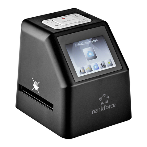
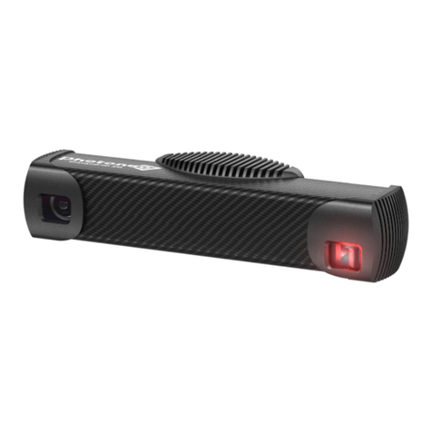
Photoneo MotionCam-3D M User manual

MotionCam-3D
User Manual and Installation Instructions

11/2020
Thank you for choosing Photoneo® MotionCam-3D. Please take a few minutes to read this manual and
become familiar with the device.
For more information on our products, accessories, replacement parts, software and services, see our website
photoneo.com/motioncam-3d/ or contact our team at [email protected].
Legal Information
Warning Notice System
This manual contains notices that should be observed in order to ensure personal safety, as well as prevent
damage to equipment. The notices referring to personal safety are highlighted with a safety alert symbol,
while notices referring only to equipment do not have a safety alert symbol. The notices are graded according
to the degree of danger.
If more than one degree of danger is present, the warning notice representing the highest degree of danger is
used. Notice warning of injury to persons with a safety alert symbol may also include a warning relating to
equipment damage.
⚠ WARNING
Indicates that death or severe personal injury may result if proper precautions are not taken.
⚠ CAUTION
When a safety alert symbol is shown, it indicates that minor personal injury can result if proper precautions
are not taken.
CAUTION
When no safety alert symbol is shown, it indicates that equipment damage can result if proper precautions
are not taken.
NOTICE
Indicates that an unintended result or situation can occur if the relevant information is not taken into account.

11/2020
Qualified Personnel
The device described in this documentation may be operated only by qualified personnel. Qualified personnel
are those who, based on their training and experience, are capable of identifying risks and avoiding potential
hazards when working with this device.
Installation, commissioning, use, decommissioning and disposal of this device should be done in accordance
with relevant documentation, in particular, its warning notices and safety instructions.
Proper Use of Photoneo Products
Please note the following:
⚠ WARNING
Photoneo products may only be used in accordance with relevant technical documentation. If products and
components from other manufacturers are used, these must be recommended or approved by Photoneo.
Proper transport, storage, installation, assembly, commissioning, operation, and maintenance are required to
ensure that the products operate safely and without any problems. The permissible ambient conditions for
storage or operation of the device must be complied with. All information provided in the relevant
documentation must be observed.

11/2020
Preface
Purpose and Scope of the Manual
This manual provides information about the installation and usage of MotionCam-3D. This document is
designed for engineers, installers, and electricians who possess a general knowledge of automation.
Trademarks
All names identified by ® are registered trademarks of Photoneo s.r.o. The remaining trademarks in this
publication may be trademarks that when used by third parties for their own purposes could violate the rights
of the owner.

11/2020
Table of Contents
Product Overview 7
General Information 7
Laser Device 8
Objects Suitable for Scanning 9
Scope of Delivery 10
Installation 11
Guidelines for Installation 11
Powering the Device & Data Connection 11
Powering Through PoE Connector 12
Powering by 24V 12
Status LEDs 13
Supported Network Topologies 14
Mounting Restrictions 15
Movement During Scanning 15
Strong Electric Field 15
Clearance for Cooling and Wiring 15
Configuration 16
PhoXi Control 16
Hardware Parameters 18
Power Over Ethernet Connector 18
Powering Requirements 18
24V Power Connector 19
Powering Requirements 19
Projection Unit 20
Environmental Conditions 20
Transport 20
Operation 20
Scanning Parameters 21
Operation Temperature 21
Cleaning Instructions 27
Compliance with Standards 28
CE 28
Laser Classification 28
Degree of Protection 28
Warranty 28
Dimensions and Illustrations 29
Bottom View: Mounting Plate 29

11/2020
Product Overview
MotionCam-3D is a high accuracy and high resolution snapshot 3D area scanning device for large work areas
that can be in motion.
The product is based on a patented CMOS sensor and Parallel Structured Light technology developed by
Photoneo. It provides the scanning quality of structured light devices with the ability to scan dynamic scenes.
The scanning process consists of capturing the scene under the laser illumination and processing and transfer
of the 3D data to the computer running the driver software (see section PhoXi Control).
General Information
General information about the device and the manufacturer can be located on the back panel of the device.
Label with manufacturer address, product name, and model, CE, FCC, WEEE
and RoHS marks, country of origin and input options.
⚠ WARNING
Hot surface warning
The surface of the processing unit may become hot to touch when the device is in use. Mount the device on a
metal mounting plate that will act as a thermal bridge to dissipate the heat or use the carbon body to
manipulate the device.

11/2020
Laser Device
The laser projector aperture is located at the right side of the front panel of the device (Figure 1). The aperture
is clearly marked with a warning label. Do not look directly into the laser projector while the device is in use.
To avoid unauthorized contact with the device or unintentional viewing of the laser beam, it is recommended
to locate the device in a restricted area and take measures to restrict laser light exposure to the surroundings.
Although diffuse reflections are not harmful, users should remove mirrors, polished objects, and similar items
from the vicinity of the device to avoid specular reflections.
All components of the device, including those sourced from 3rd party suppliers, conform fully with all
applicable European directives and regulations.
The device uses the following labels and warning systems. Apart from the laser aperture label, all are located
on the back panel of the device.
⚠ WARNING
This device is a laser product. Do not deliberately look into the laser beam. This may cause injury to the retina.
The use of protective eyewear is usually not necessary. The appropriate laser class label is present on the
back of the device.
Figure 1: MotionCam-3D laser aperture location
Laser radiation hazard warning symbol.

11/2020
Objects Suitable for Scanning
MotionCam-3D uses laser light to acquire 3D data. It can capture dynamic scenes as well as static ones. Smoke
and particles dispensed in the air will negatively influence the 3D data. Always bear in mind that
MotionCam-3D can see no more than you can see with the naked eye.
Objects most suitable for scanning are (including and not limited to):
■rough surface objects, for example, wood, rubber, etc.
■objects with a matte finish, such as sand-blasted aluminum, cast iron, etc.
■molded, un-polished plastic materials.
Some objects not suitable for scanning (including and not limited to):
■mirrors and polished metals,
■most liquids (e.g. water, oil),
■translucent and transparent objects (e.g. glass, transparent plastic)
Laser aperture label. Designates the place from which laser radiation is emitted.
Laser Class 3R devices
Laser radiation warning with laser class label. The serial number of the device can be
found above the warning labels.
Label specifying wavelength, average power, pulse energy and pulse length of the
laser. Used on MotionCam models S+, M, M+, L.
Label specifying wavelength, average power, pulse energy and pulse length of the
laser. Used on MotionCam model S.

11/2020
Scope of Delivery
■Selected model of MotionCam-3D
■Desktop PoE injector (input: 90 ~ 264VAC, output: 33.6W, 56V, IEEE802.3at) with power cable (1.8m)
■Ethernet cable M12-X male - RJ45 male, 5m, PUR
NOTICE
Software components are needed for operation of the MotionCam-3D. See section Configuration for more
information.

11/2020
Installation
Guidelines for Installation
MotionCam-3D has been designed to allow easy installation.
The MotionCam-3D can be mounted :
1
■Using a mounting plate of suitable size and 4 M4 screws.
⌑This is preferred mounting method to ensure rigid mounting of the device to avoid unwanted
movement
■Using a M8 screw.
■On a tripod using a 3/8-16 UNC screw.
To install MotionCam-3D:
1. Mount MotionCam-3D using any preferred method. Refer to Dimensions and Illustrations.
2. When mounting MotionCam-3D, ensure that an appropriate scanning distance is set between the
MotionCam-3D and the scanned object and eliminate any potential obstacles.
3. Connect MotionCam-3D to the computer or local network and plug it into the power. See the section
Powering the device & Data connection for more details.
4. Download and install the PhoXi Control application from the Photoneo webpage.
5. Run the PhoXi Control application and try to make your first scan. Please refer to the PhoXi Control User
Guide.
Powering the Device & Data Connection
There are two possibilities to power the device:
1 A CAD model of MotionCam-3D is available at: www.photoneo.com/dl/cad/motioncam
Figure 2: Mounting plate

11/2020
1. Using the M12-X Power over Ethernet (PoE) connector (providing both power and data connection)
2. Using the M12-A 24V power connector to power the device and the M-12X connector for data transfer
Figure 3: Back panel of MotionCam-3Ds
Powering Through PoE Connector
1. Connect 1Gbps capable (standardly delivered) ethernet cable to the PoE injector IN port
2. Connect the M12-X RJ45 cable to MotionCam-3D and to the PoE injector OUT port
3. Plug in the power cable of the PoE injector
Figure 4: Connection schematics for PoE
Powering by 24V
1. Connect the M12-X RJ45 cable to MotionCam-3D and to your computer or switch
2. Connect the M12-A to MotionCam-3D and to the 24V adapter
NOTICE
It is recommended to use PoE connection to power the device.

11/2020
Figure 5: Connection schematics for 24V power
Status LEDs
Figure 6: Status LEDs of correctly working device
#
LED Name
Color
Description
1
POWER
Green
Red
Off
Power ON and OK
Power ON, power on processing unit not OK
No power
2
STATUS
Green
Red
Firmware ready
HW fault
3
ETH1
Flashing green
Green
Off
Activity on link
No activity on link
Link is down
4
ETH2
Green
Off
Gigabit ethernet connected
No gigabit ethernet

11/2020
Supported Network Topologies
The following network topologies are supported by MotionCam-3D:
■Direct connection to a computer
Figure 7: Direct connection
■Scanner connected to a switch
Figure 8: Connected to a switch
The following network topology is not supported by MotionCam-3D:
■Scanner connected to a router:
Figure 9: Connecting the Scanner through router is not supported
Note:
■Connecting to the Scanner via WiFi is not recommended as it is slower and less reliable.

11/2020
Mounting Restrictions
Movement During Scanning
Strong Electric Field
As a general rule, always isolate low-voltage, logic-type devices such as MotionCam-3D from devices that are
high voltage and generate high electrical noise. Carefully consider the routing of the wiring for the devices in
the panel as well. Avoid placing low-voltage signal wires and communication cables in the same tray with AC
power wiring and high energy, rapidly-switched DC wiring.
Clearance for Cooling and Wiring
MotionCam-3D is designed to be cooled through natural convection cooling. In order to ensure adequate
cooling, a clearance of at least 25 mm above and below the device must be allowed. When planning placement
of MotionCam-3D, consider placing heat-generating and electronic-type devices in the cooler areas. By
reducing exposure to high-temperature environments, you can extend the operating life of the electronic
devices considerably.
NOTICE
If several MotionCam-3Ds are connected to a computer with several ethernet adapters, using static IP
addresses on different subnets is recommended.
NOTICE
It is allowed to mount MotionCam-3D on moving constructions or robotic arms. MotionCam-3D is able to
capture dynamic scenes as well as static scenes
NOTICE
It is recommended to mount MotionCam-3D on a metal plate that will act as a thermal bridge and dissipate
the heat produced by the processing unit away from it.

11/2020
Configuration
PhoXi Control
PhoXi Control is a computer application that acts as a driver for the Photoneo scanning devices. It allows the
user to control the MotionCam-3D manually through graphical user interface or programmatically through the
provided API.
The GUI is primarily used to set up the scanning environment, to configure advanced scanning parameters and
to visualize the output. In addition, the GUI can also be used as a powerful debugging tool for development
with the API. Calls to the API trigger the same response in the GUI as user inputs. After triggering the scan by
calling API method, the application will execute the scan, send it as an output of the call and display it
simultaneously in the GUI.
The API serves as a central platform for building custom applications for PhoXi 3D Scanners and
MotionCam-3Ds. In order to facilitate the development process and reduce computing demands all
computations are performed on the device itself.
Figure 11: PhoXi Control – Network Discovery

11/2020
Hardware Parameters
Power Over Ethernet Connector
Figure 12: PoE connector pinout, view from the mating side
Powering Requirements
Connector type: M12 X coded, 1404741
Figure 13: Contact assignments of the M12 and RJ45 plug
PoE Standard
IEEE802.3at
Operating voltage Ue DC
min. 55 V
Residual ripple maximum (% of Ue)
0.5 %
Rated operating current Ie (Imax)
0. 360 A (0.6A)
Minimum Power
33 W
Shielding
Fully Shielded RJ45
Transfer data rate
1 Gbit
Maximum recommended cable length
20 m

11/2020
24V Power Connector
Figure 14: 24V Power & GPIO pinout, view from the mating side
* devices with laser safety interlock needs to be ordered separately
Powering Requirements
* for cable length over 10 m please ensure operating voltage at minimum 28 V
Connector type: M12 A coded, M12A-08PMMP-SF8001
Pin
Cable Color
Pinout
Function
1
White
DC_IN
+ 24V
2
Brown
OPTO_IN2_GND
*laser interlock ground
3
Green
GND
ground
4
Yellow
OPTO_IN1
hardware trigger input signal
5
Grey
OPTO_IN1_GND
-
6
Pink
OPTO_OUT
hardware trigger output signal
7
Blue
OPTO_OUT_GND
-
8
Red
OPTO_IN2
*laser interlock signal
Operating DC voltage Ue (Umin-Umax)
24V (20 - 30 V)
Residual ripple maximum (% of Ue)
2%
Rated operating current Ie (Imax)
1A (2A)
Minimum Power
60 W
Maximum recommended cable length
20 m *

11/2020
Projection Unit
Environmental Conditions
Transport
Operation
Projection width horizontal
47.5° ± 1°
Projection width vertical
36.0°± 2°
Model
S
S+, M, M+, L
Light source
Visible red light (laser)
Laser class
LC3R
LC3R
Wavelength
639nm
637nm
Average power
0.314mW
4.32mW
Pulse energy
382nJ
93.7μJ
Pulse length
0.96ms
1.32ms
Ambient temperature
From -20°C to 50°C (max gradient
10°C/hour)
Humidity
From 0% to 95% non-condensing
Atmospheric pressure
From 1080hPa to 660hPa (corresponding to
an altitude of -1000m tp 3500m)
⚠ CAUTION
Please ensure that the device is always transported in its original casing or that it is properly cushioned for
transport.
Operating temperature for optimal scanning performance
From 22°C to 25°C
Overall operating temperature
From 0°C to 45°C
Humidity
From 0% to 95% non-condensing
Atmospheric pressure
From 1080hPa to 660hPa (corresponding to
an altitude of -1000m tp 3500m)
Maximum acceleration
20ms-2
Other manuals for MotionCam-3D M
1
This manual suits for next models
3
Table of contents
Other Photoneo Scanner manuals

Photoneo
Photoneo PhoXi 3D Scanner XS User manual

Photoneo
Photoneo PhoXi 3D Scanner M User manual

Photoneo
Photoneo PhoXi User manual

Photoneo
Photoneo PhoXi 3D Scanner S User manual

Photoneo
Photoneo PhoXi 3D Scanner S User manual

Photoneo
Photoneo PhoXi 3D Scanner M User manual

Photoneo
Photoneo PhoXi XS User manual

Photoneo
Photoneo PhoXi User manual

Photoneo
Photoneo PhoXi User manual