PHOTONIS NOCTURN XL User manual

Digital Low-Light CMOS Camera
Engineering User Guide
NOCTURN Digital Low Light CMOS Camera
XL Monochrome Camera Module
May 2015
Doc. No: 200-LC-4019
Version C.04
PHOTONIS Digital Imaging, LLC
6170 Research Road | Suite 208
Frisco, TX USA 75033
T: +1 (469) 713-6108
F: +1 (469) 713-2880
www.photonis.com

2|
© 2015 PHOTONIS Digital Imaging, LLC.
All Rights Reserved
This document may not be reproduced, in whole or in part, without prior written consent of
PHOTONIS Digital Imaging, LLC. The information furnished in this document is believed to be correct
at the time of publication but is not guaranteed and is subject to change without prior notice. No
liability is assumed by PHOTONIS for its use. No claims or warranties are made as to the application of
PHOTONIS products. Customers should verify they have the correct documentation before use.
NVT 200-LC-4019 ©2015 PHOTONIS Digital Imaging LLC
Revision: C.04 All Rights Reserved
Page 2 of 39

Document Revisions |NOCTURN XL Camera | 3
Document Revisions
Date Version
Number
Document Changes
Dec. 12, 2013 A-1 Initial Draft
Jan. 17, 2014 A-2 Initial Release
May 5, 2014 B-1 Update for software version 575
July 2, 2014 C-1 Update for software version 607
August 4, 2014 C-2 Update for software version 610
May 11, 2015 C-3 Update for software version 684
May 13, 2015 C-4 Corrected precision on agc bhipccontrast and blopccontrast controls
PHOTONIS Digital Imaging LLC NVT 200-LC-4019
6170 Research Road Suite 208 Revision: C.04
Frisco, TX USA 75033 Page 3 of 39

4|
Table of Contents
Document Revisions.................................................................................................................................................................3
Table of Contents ......................................................................................................................................................................4
Safety Summary .........................................................................................................................................................................6
Introduction.................................................................................................................................................................................7
Scope and Purpose ..............................................................................................................................................................7
Product Configuration ........................................................................................................................................................8
Product Specifications ........................................................................................................................................................9
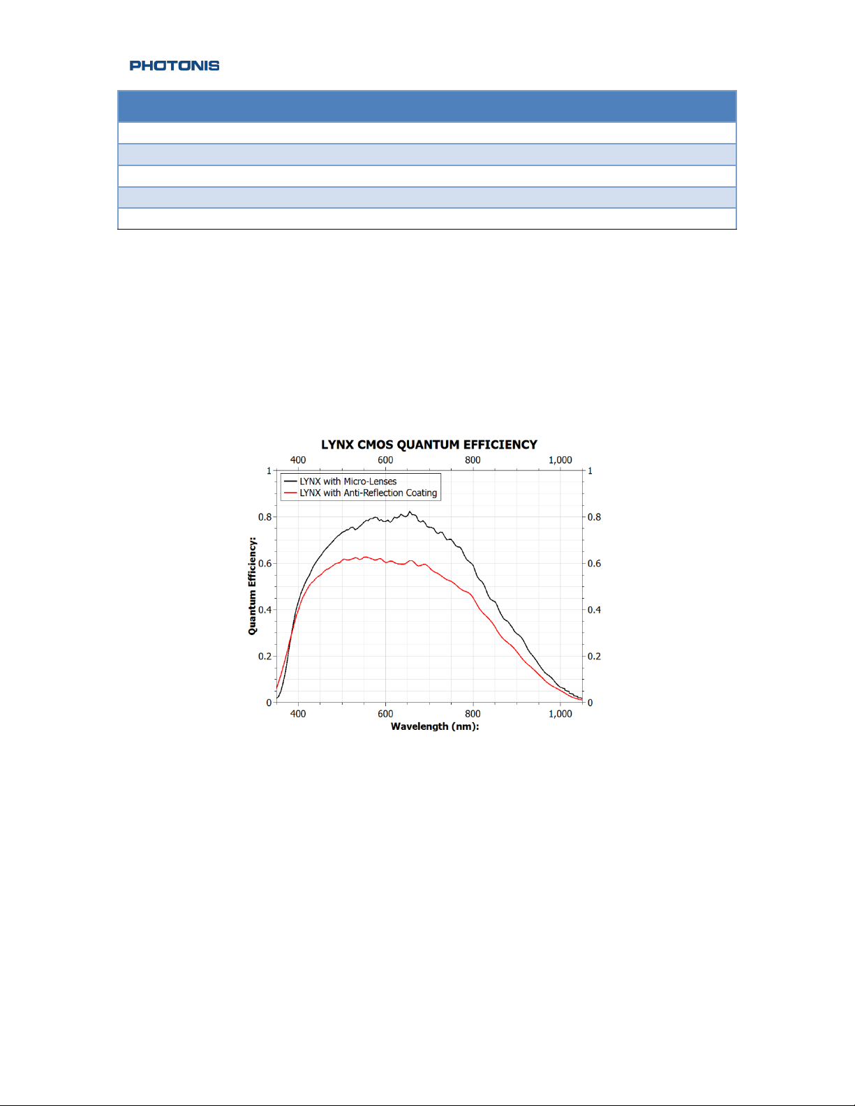
Quantum Efficiency...........................................................................................................................................................10
Getting Started with the Camera......................................................................................................................................11
Unpacking Instructions....................................................................................................................................................11
USB Driver Installation .....................................................................................................................................................13
CameraLink®Frame Grabber Setup.............................................................................................................................14
Initial Power Up ..................................................................................................................................................................15
Camera Controls .....................................................................................................................................................................16
Basic Communication Settings.....................................................................................................................................16
Communication Protocol................................................................................................................................................16
Camera Serial Commands ...................................................................................................................................................19
Top Level Commands.......................................................................................................................................................19
Baud Rate Commands......................................................................................................................................................20
Echo Commands................................................................................................................................................................21
CS Commands.....................................................................................................................................................................21
Video Commands ..............................................................................................................................................................26
Picture Commands............................................................................................................................................................28
CameraLink Commands ..................................................................................................................................................29
Analog Video Commands...............................................................................................................................................29
NUC Commands.................................................................................................................................................................30
Temperature Commands................................................................................................................................................30
Transfer Commands..........................................................................................................................................................31
Draw Commands ...............................................................................................................................................................31
AGC Commands .................................................................................................................................................................33
Maintenance.............................................................................................................................................................................36
Storage .......................................................................................................................................................................................37
Quality ........................................................................................................................................................................................38
NVT 200-LC-4019 ©2015 PHOTONIS Digital Imaging LLC
Revision: C.04 All Rights Reserved
Page 4 of 39

Table of Contents
|NOCTURN XL Camera | 5
Acceptance Test Protocol ...............................................................................................................................................38
Warranty................................................................................................................................................................................38
PHOTONIS Digital Imaging LLC NVT 200-LC-4019
6170 Research Road Suite 208 Revision: C.04
Frisco, TX USA 75033 Page 5 of 39

6|
Safety Summary
WARNING and CAUTION statements have been strategically placed throughout the text prior to
operating or maintenance procedures, practices, or conditions considered essential to the protection
of personnel (WARNING) or equipment and property (CAUTION). NOTES emphasize necessary and
important data. CAUTIONS and NOTES appear in the text as applicable. Definitions for WARNINGS,
CAUTIONS and NOTES are as follows:
WARNING
A warning indicates an operation, condition, or statement, etc., which, if
not strictly observed, could result in injury to or death of personnel.
CAUTION
A caution indicates an operation, maintenance procedure, or condition,
etc., which, if not strictly observed, could result in damage to, or
destruction of, equipment or loss of hardware performance or function.
NOTE
A note indicates an essential operating or maintenance procedure,
condition or statement or explanatory text.
NVT 200-LC-4019 ©2015 PHOTONIS Digital Imaging LLC
Revision: C.04 All Rights Reserved
Page 6 of 39

Introduction |NOCTURN XL Camera | 7
Introduction
Scope and Purpose
The NOCTURN XL monochrome (see Figure 1) is a rugged low light camera module that features high-
definition resolution, high sensitivity and high dynamic range with low power consumption. Powered
by PHOTONIS’ 1 inch optical format 1280×1024 pixel (SXGA) Lynx CMOS sensor, the NOCTURN
provides real-time imaging capabilities (from daylight to one quarter moon scene illumination) in the
visible and near infrared spectrum. Its small size, weight and power (SWaP) make this camera module
ideal for integration into aerial, mobile and hand-held surveillance systems.
With its 9.7µm × 9.7µm pixel pitch and <4e- median read noise, the NOCTURN provides unsurpassed
signal to noise at low light with video rates up to 100 frames per second. Leveraging PHOTONIS
expertise in night vision imaging, the NOCTURN electronics incorporates a multitude of functions to
enhance the low light level performance. This camera features automatic gain control (AGC),
automatic exposure control (AEC), high dynamic range (HDR), non-uniformity correction (NUC) and
advanced image enhancement, allowing the NOCTURN to provide continuous situational awareness
without compromising mobility and SWaP. The “XL” version of the NOCTURN has both a CameraLink®
compatible 10-bit digital video output as well as PAL/NTSC analog video output.
Figure 1: Front View of the NOCTURN XL Camera
This user guide provides a detailed overview of the functionality, operation and communication
interface with the camera accessible by a user. The hardware interface for the camera is only briefly
discussed in this guide; the user should refer to the NOCTURN XL Electro-Mechanical ICD for a detailed
description. Please contact PHOTONIS Digital Imaging technical support for details that are not
covered in this guide.
PHOTONIS Digital Imaging LLC NVT 200-LC-4019
6170 Research Road Suite 208 Revision: C.04
Frisco, TX USA 75033 Page 7 of 39

8|
Product Configuration
The “XL” model indicates that the NOCTURN camera has an integrated interface board that can be
used to output digital video over a Camera Link® compatible interface as well as NTSC/PAL composite
video. The back panel of this NOCTURN configuration is shown in Figure 2.
Figure 2: Back Side View of the NOCTURN XL Camera
The user can independently turn on the CameraLink® compatible digital and analog video output via
the serial command over the USB interface. Additionally, the NOCTURN XL is delivered with a tripod
mount adapter that can be easily bolted on to any side of the camera chassis. For full pin-out of the
NOCTURN XL camera please refer to the NOCTURN XL Electro-Mechanical ICD.
The NOCTURN XL can be powered either via the USB interface from a personal computer (cable not
provided) or through the J301 external power and IO connector (see Table1 for power input
specification). The NOCTURN XL Electro-Mechanical ICD provides both the pin-out of and mating
connector part number for J301.
Table1: NOCTURN XL Input Power Specifications
Parameter
Description
Min
Typ
Max
Units
Vin
Input Voltage
5
--
15
V
Icc
Input Current1
--
3502
--
mA
1Digital video output only without image processing enabled
2Measured with 5VDC input
NVT 200-LC-4019 ©2015 PHOTONIS Digital Imaging LLC
Revision: C.04 All Rights Reserved
Page 8 of 39

Introduction |NOCTURN XL Camera | 9
Product Specifications
Detailed specifications for the NOCTURN XL camera are given in Table 2.
Table 2: NOCTURN XL Specifications
Parameter
Specification
Sensor Resolution
1280 × 1024 Pixels
Sensor Pixel Pitch
9.7 µm × 9.7 µm
Sensor Well Capacity
> 25000 e-
Sensor Dynamic Range
> 60 dB
Sensor Read Noise
< 4 e- med. (60fps Mode)
Sensor Quantum Efficiency
> 60% at 600nm
Frame Rate
3
50, 60 or 100Hz with full field resolution (user adjustable)
Sensor Image Lag
< 0.1 %
Sensor Shutter Mode
Rolling
Lens Mount
CS
Dimensions (W × H × D)
34.1 mm × 36.6 mm × 37.4 mm
Weight
< 85 grams
Digital Video Output
10/8 bit Base CameraLink® compatible
Analog Video Output
NTSC/PAL (user configurable)
Communication
Serial via CameraLink® compatible interface or USB
Image Correction
Bad pixel replacement and 2 points non uniformity
correction
Contrast Enhancement
Contrast stretching, equalization and adaptive equalization
Gain Control
Automatic gain and exposure control or manual
Digital Zoom
8X (0.001 increment resolution)4
Synchronization
Frame start trigger (2 to 12V)
Analog output strobe reference (2 to 12V)
Windowing5
Full field of view down to 2 lines vertical resolution
OSD
Full on screen display capability with text, standard
geometrical shape and graphics
Snapshots
On board capture of *.JPG (8b) or *. PGM (8/10b)
3By default the camera is optimized only for 60 and 100fps mode. Please contact PHOTONIS if you need the camera optimized
for 50fps.
4Digital zoom only available in the 60 and 50fps modes
5Feature only available on the digital video output interface with OSD disabled
PHOTONIS Digital Imaging LLC NVT 200-LC-4019
6170 Research Road Suite 208 Revision: C.04
Frisco, TX USA 75033 Page 9 of 39

10 |
Parameter
Specification
Camera/Imaging Start Up Time
< 5 seconds
Operating Temperature
-40° to +60° C
Storage Temperature
-50° to +80° C
Input Voltage
USB powered or external +5 to +15 VDC
Power (Typical)
60/50Hz mode < 1.8W (typ.); 100Hz mode: <2.25W
Quantum Efficiency
The typical quantum efficiency as a function of wavelength for the LYNX CMOS for versions with and
without micro-lenses is shown in Figure 3.
Figure 3: LYNX CMOS Quantum Efficiency Curve
NVT 200-LC-4019 ©2015 PHOTONIS Digital Imaging LLC
Revision: C.04 All Rights Reserved
Page 10 of 39

Getting Started with the Camera |NOCTURN XL Camera | 11
Getting Started with the Camera
This section provides some key information on how to unpack the camera and initial setup.
WARNING
The NOCTURN XL cameras contain electrostatic sensitive parts and
assemblies and should be handled within protected areas and in
accordance with industry standard electrostatic discharge (ESD)
protective handling procedures. Under no circumstances, should the
camera be disassembled unless directed to do so by PHOTONIS personnel.
Disassembly of the camera and damage to the anti-tamper sticker on the
side of the camera will void the warranty.
Unpacking Instructions
Table 3: Unpacking Instructions for the NOCTURN XL Camera
Description
Image
Inspect shipping container and notify
PHOTONIS personnel of any damage that
may have occurred during shipping.
Record the camera serial number located on
the side of the shipping container for your
records. This number is also engraved on the
bottom of the camera. You will need that
number to be able to receive technical
support with your product.
PHOTONIS Digital Imaging LLC NVT 200-LC-4019
6170 Research Road Suite 208 Revision: C.04
Frisco, TX USA 75033 Page 11 of 39

12 |
Description
Image
Open shipping container by breaking the
PHOTONIS seal and lifting the cardboard lid.
Remove the antistatic bag containing the
camera module from the suspended clear
plastic clamshell.
Unseal antistatic bag and remove camera
module using proper ESD procedures.
Inspect camera module for proper
configuration and potential shipping
damage. Immediately report any problem to
PHOTONIS personnel.
NVT 200-LC-4019 ©2015 PHOTONIS Digital Imaging LLC
Revision: C.04 All Rights Reserved
Page 12 of 39

Getting Started with the Camera |NOCTURN XL Camera | 13
USB Driver Installation
Once the camera is unpacked, please install the USB drivers for your target operating system located
on the Silicon Labs website (www.silabs.com).
Additionally, if communication with camera has to be done over the USB interface, terminal emulator
software such as Tera Term (http://ttssh2.sourceforge.jp/) is needed to send and receive serial
message between the control PC and the camera.
CAUTION
If using the USB interface to power the camera, the NOCTURN XL USB driver
must first be installed on the target control PC to avoid connection
problems.
To install the USB driver on Windows operating system, please follow the instructions in Table 4.
Table 4: USB Driver Installation for Windows
Description
Image
Download the latest CP210x USB to UART Bridge
VCP drivers (v6.6.1 or newer is recommended)
from the Silicon Labs website
http://www.silabs.com.
Unzip the downloaded driver file.
Double click the installer (please note that you
need administrator privilege to install the drivers):
•CP210xVCPInstaller_x64 (64b OS)
•CP210xVCPInstaller_x86 (32b OS)
On the installer Welcome screen click the Next
button.
On the License Agreement screen, select “I accept
this agreement” and then click the Next Button.
PHOTONIS Digital Imaging LLC NVT 200-LC-4019
6170 Research Road Suite 208 Revision: C.04
Frisco, TX USA 75033 Page 13 of 39

14 |
Wait
for the installation to complete. Once it is
finish you will see the following screen. Just click
Finish to complete the installation.
CameraLink®Frame Grabber Setup
Please refer to the CameraLink® frame grabber manual to setup the configuration to match the
parameters shown in Table 5.
Table 5: CameraLink® Frame Grabber Configuration Details
Parameter
Value
Unit
Pixel Clock per Tap (30/50/60fps Mode) 48 MHz
Pixel Clock per Tap (100fps Mode) 72 MHz
Number of Taps 2 Interlaced Vertically NA
Grayscale Resolution 10 Bits
Data Width pre Valid 8 Pixels
Data Height pre Valid 1 Line
Data Width Valid 1280 Pixels
Data Height Valid 1024 Pixels
Data Width post Valid 0 Pixels
Data Height post Valid 0 Pixels
For example, with the ImperX FrameLink express frame grabber the configuration should be setup as
shown in Figure .
Figure 4: ImperX FrameLink Express Frame Grabber NOCTURN XL Setup
NVT 200-LC-4019 ©2015 PHOTONIS Digital Imaging LLC
Revision: C.04 All Rights Reserved
Page 14 of 39

Getting Started with the Camera |NOCTURN XL Camera | 15
Initial Power Up
Once the USB driver installation and CameraLink® frame grabber setup is complete, connect an SDR
CameraLink® compatible cable between the S501 connector on the NOCTURN XL and a PC frame
grabber (see Figure). Alternatively, an SMA to BNC connector adapter can be connected between the
J601 NOCTURN XL connector and an analog video monitor (either PAL or NTSC)6.
Figure 5: Hardware Connection Between the NOCTURN and PC
Once the video output cable is connected, plugin a micro-USB cable (not supplied with the camera)
between the J304 connector on the NOCTURN XL camera and the host PC with the installed USB drivers.
The status LED on the back of the NOCTURN XL should turn green as seen in Figure .
Figure 6: LED on the Back of the NOCTURN XL Turns Green when USB Power is Applied
At this point, the camera should be outputting video data. Turn on the frame grabber image
acquisition software to display the digital video output from the camera.
6By default the analog video output of the camera is turned off and needs to be enabled through the serial interface.
Hardware Configuration with
USB Power and Camera Link®
Digital Video
Camera Link®
USB Communication
& Power
PHOTONIS Digital Imaging LLC NVT 200-LC-4019
6170 Research Road Suite 208 Revision: C.04
Frisco, TX USA 75033 Page 15 of 39

16 |
Camera Controls
The NOCTURN XL is controlled by a serial communication protocol that can be addressed over the USB
or the CameraLink® serial interface link. This section of the user guide provides an overview of the
command and associated syntax to control the camera as well as the serial port settings needed.
Basic Communication Settings
The serial communication should be set with the following configuration for both the USB and the
CameraLink®:
•Number of bits: 8
•Baud rate: 115200 bps
•Parity: none
•Number of stop bits: 1 bit
•Flow control: none.
NOTE
The NOCTURN XL cameras are shipped with a default baudrate of
115200bps. The latter can be changed by the user by using the “baudrate”
command described in this section.
Communication Protocol
The protocol to communicate with the NOCTURN XL is based on ASCII printable messages. A carriage
return and line feed must be sent following a command. After power is initially applied to the camera
will send “{BOOT_DONE}” indicating that the camera is ready to receive commands. Once an initial
message has been sent to the camera, a “>” will appear at the console when the camera is ready to
accept new messages. The camera will answer “>OK” to all user command that are accepted and
“>Error <error message>” when an error occur.
A standard message to the camera should have the following architecture:
<Command><Optional Payload><CR>7<LF>8.
NOTE
With this current firmware/software release, the camera no longer echos
command by default. The echo can be re-enabled by using the “echo”
command. To enable the echo on the USB port, type
“echo usb 1<CR><LF>” at the serial interface. This can be saved as power
on default state for the camera by saving the flash configuration (type
“save flash<CR><LF>”).
7Carriage return
8Line feed
NVT 200-LC-4019 ©2015 PHOTONIS Digital Imaging LLC
Revision: C.04 All Rights Reserved
Page 16 of 39

Camera Controls |NOCTURN XL Camera | 17
The following examples demonstrate the communication protocol (please refer to the following
sections for camera syntax details) and assumes that:
•Example 1: displaying the help menu after initial boot up
{BOOT_DONE}<CR><LF> //camera boot complete
?<CR><LF> //serial message sent by user to display help menu
//response from the camera
==============================================================<CR><LF>
?/help Display this console help menu<CR><LF>
baudrate Set serial port baudrate<CR><LF>
log Print system boot log<CR><LF>
status Reprint signon information<CR><LF>
update [user|factory|help] Print flash update menu (default=user) <CR><LF>
PIC Print Picture menu<CR><LF>
CL Print CameraLink menu<CR><LF>
TEMP Print the temperature sensor menu<CR><LF>
XFERPrint file transfer I/O menu<CR><LF>
DR Print OSD menu<CR><LF>
==============================================================<CR><LF>
> //camera ready for next command
•Example 2: requesting contrast function help
> //camera ready for command
video contrast ?<CR><LF> //serial message sent by user to get contrast help
//response from camera
VIDEO contrast Selects contrast enhancement: <CR><LF>
0 - No enhancement<CR><LF>
1 - histogram stretching<CR><LF>
2 - histogram equalization<CR><LF>
PHOTONIS Digital Imaging LLC NVT 200-LC-4019
6170 Research Road Suite 208 Revision: C.04
Frisco, TX USA 75033 Page 17 of 39

18 |
3 - limited equalization<CR><LF>
4 - histogram unrounded equalization<CR><LF>
99 - auto contrast (table driven) <CR><LF>
> //camera ready for next command
•Example 3: changing the contrast
> //camera ready for command
video contrast 1<CR><LF> //serial message sent by user to enable hist. stretching
OK<CR><LF> //reply from camera that command was accepted
>//camera ready for next command
•Example 4: query contrast setting
> //camera ready for command
video contrast <CR><LF> //serial message sent by user to get contrast status
CONTRAST = 1<CR><LF> //reply that contrast is set to hist. stretching
OK<CR><LF> //reply from camera that command was accepted
>//camera ready for next command
•Example 5: invalid parameter resulting in an error
> //camera ready for command
video contrast 500<CR><LF>//message sent by user with invalid contrast setting
//error response from the camera
Error 6012, Video Pipeline: Invalid contrast parameter<CR><LF>
<CR><LF> //blank line sent by camera
>//camera ready for next command
NVT 200-LC-4019 ©2015 PHOTONIS Digital Imaging LLC
Revision: C.04 All Rights Reserved
Page 18 of 39

Camera Serial Commands |NOCTURN XL Camera | 19
Camera Serial Commands
The following section contains all of the serial command available on the NOCTURN XL.
Top Level Commands
Table 6: Top Level Commands
Command
Optional Payload
Description
help
Display console help menu
?
Display console help menu
baudrate
(see Baud Rate
Commands)
Set serial port baudrate
echo
(see Echo Commands)
Set the serial port echo state
log
Print system boot log, used for debugging
user/camera problems
save
?/help
flash
user
factory keyword
Display help for command
Save current flash settings (baudrate etc)
Save changes to user settings.ini file
Save changes to factory settings.ini file
status
Reprint sign on information
update
?/help
user
factory
Flash update menu help
Update user flash
Update factory flash
CS
?
(see CS Commands)
(For factory use only) Camera sensor command
menu. Type “?” to get embedded help menu
VIDEO
(see
Video Commands)
Video pipeline command menu
PIC
(see Picture Commands
Picture command menu
CL
(see CameraLink
Commands
CameraLink® command menu
AV
(see Analog Video
Commands)
Analog Video command menu
NUC
(see
NUC Commands)
Non uniformity correction command menu
TEMP
(see Temperature
Commands)
Print the temperature sensor menu
XFER
(see Transfer Commands)
Print file transfer I/O menu Type “?” to get
embedded help menu
DR
(see Draw Commands)
Draw OSD menu
AGC STATUS
(see
AGC Commands)
Prints AGC settings and available commands
PHOTONIS Digital Imaging LLC NVT 200-LC-4019
6170 Research Road Suite 208 Revision: C.04
Frisco, TX USA 75033 Page 19 of 39

20 |
Baud Rate Commands
By default the NOCTURN XL camera is shipped with a preset baud rate of 115200bps. The baud rate
command allows you to both query the current baud rate setting but also change it.
All valid serial command shown in Table 7 should be sent as:
baudrate <Command> <Optional Payload><CR><LF>
Table 7: Baud rate Commands
Command
Optional Payload
Description
USB
?
Display baudrate help and current setting for the
USB port (main external RS-232 port)
USB
921600
460800
230400
115200
57600
38400
28800
19200
9600
Set the USB baud rate to 921600bps
Set the USB baud rate to 460800bps
Set the USB baud rate to 230400bps
Set the USB baud rate to 115200bps
Set the USB baud rate to 57600bps
Set the USB baud rate to 38400bps
Set the USB baud rate to 28800bp
Set the USB baud rate to 19200bps
Set the USB baud rate to 9600bps
AUX
?
Display baudrate help and current setting for the
AUX port (CameraLink COM)
AUX
921600
460800
230400
115200
57600
38400
28800
19200
9600
Set the AUX baud rate to 921600bps
Set the AUX baud rate to 460800bps
Set the AUX baud rate to 230400bps
Set the AUX baud rate to 115200bps
Set the AUX baud rate to 57600bps
Set the AUX baud rate to 38400bps
Set the AUX baud rate to 28800bp
Set the AUX baud rate to 19200bps
Set the AUX baud rate to 9600bps
DBG
?
Display baudrate help and current setting for the
debug port
DBG
921600
460800
230400
115200
57600
38400
28800
19200
9600
Set the DBG baud rate to 921600bps
Set the DBG baud rate to 460800bps
Set the DBG baud rate to 230400bps
Set the DBG baud rate to 115200bps
Set the DBG baud rate to 57600bps
Set the DBG baud rate to 38400bps
Set the DBG baud rate to 28800bp
Set the DBG baud rate to 19200bps
Set the DBG baud rate to 9600bps
NVT 200-LC-4019 ©2015 PHOTONIS Digital Imaging LLC
Revision: C.04 All Rights Reserved
Page 20 of 39
Table of contents
Other PHOTONIS Digital Camera manuals