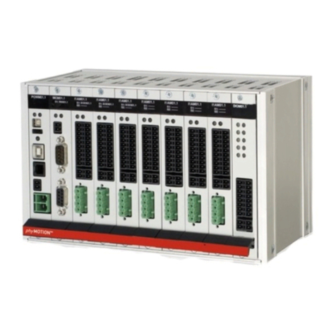
Manual INAM01 / INAM02 / INAM03
MA 1275-A011 EN 6
2 Contents
1Information ..............................................................................................................3
2Contents...................................................................................................................6
3INAM (Internal Amplifier-Module) –Module Overview..........................................7
4Technical Data........................................................................................................10
4.1 Declaration of Incorporation: Modules gen. & External Supply EXT....................10
4.2 Declaration of Conformity: Modules with Internal Supply INT..............................12
4.3 Mechanical Data.................................................................................................14
4.4 Features.............................................................................................................15
4.5 Functions............................................................................................................18
5Installation..............................................................................................................20
5.1 Mechanical Installation.......................................................................................20
5.1.1 INAM01 .......................................................................................................20
5.1.2 INAM02 .......................................................................................................22
5.2 Electrical Installation...........................................................................................22
5.2.1 Connectors - Overview................................................................................22
5.2.2 Pin Assignment............................................................................................23
5.2.3 Stepper Motor Connection X5......................................................................25
5.2.4 Limit Switch Connection X2.........................................................................29
5.2.5 Option: Encoder Connection X1...................................................................30
5.2.6 Option: Resolver, LVDT or RVDT Connection X1.......................................34
5.2.7 Option: Motor Temperature Sensor Connection X3/X4................................39
6Commissioning ......................................................................................................41
6.1 Diagnostics by the LEDs.....................................................................................42
6.2 Parameterising the Module.................................................................................43
7Principles of Positioning .......................................................................................44
8Service ....................................................................................................................45
9Warranty, Disclaimer and Registered Trademarks ..............................................46
9.1 Disclaimer ..........................................................................................................46
9.2 Warranty.............................................................................................................46
9.3 Registered Trademarks......................................................................................46
10Index........................................................................................................................47
