manuals.online logo
Brands
  1. Home
  2. •
  3. Brands
  4. •
  5. Honeywell
  6. •
  7. Control Unit
  8. •
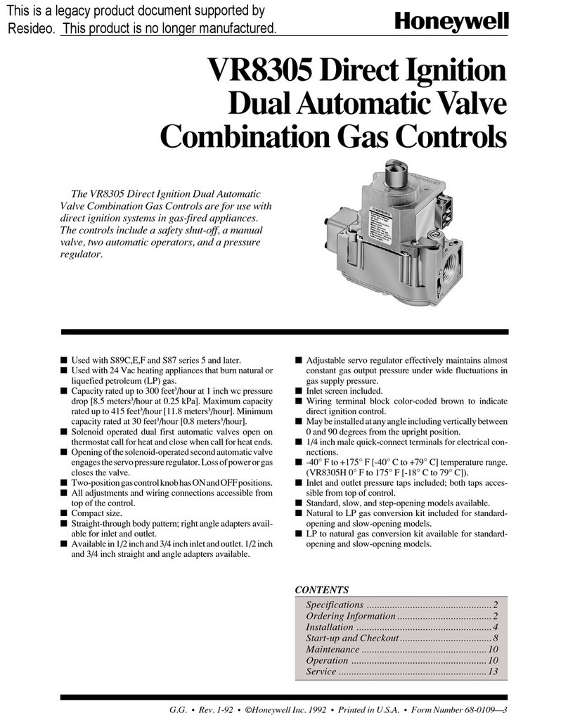
  9. Honeywell VR4611VA1007 User manual

Honeywell VR4611VA1007 User manual

INSTRUCTION SHEET
GAS CONTROL WITH INTEGRATED 1:1 GAS/AIR REGULATOR FOR
AUTOMATIC IGNITION SYSTEMS
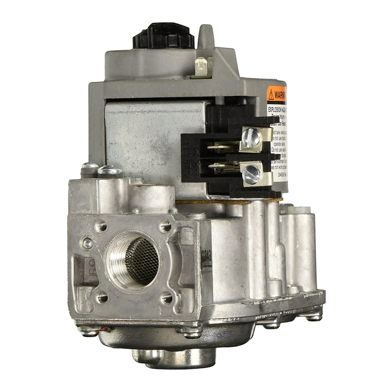
VR4611VA1007
EN1R--9170 0109R1--NE
APPLICATION
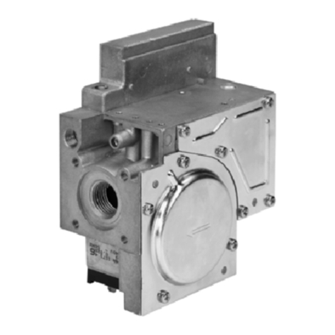
VR4611VA 1007 gas control has been specially developed for
application in domestic premix appliances with intermittent
pilot ignition.
VR4611VA 1007 gas control is used in a system context in
conjunction with fan control, an intermittent pilot ignition (IP)
control module and associated devices to provide
programmed safe light--up and supervision of the main burner
of an appliance.
VR4611VA 1007 gas control is intended to be used for natural
gas and LP gas.
VR4611VA 1007 gas control is approved in accordance with
existing european standards.
DESCRIPTION
VR4611VA 1007 gas control performs all the functions
required to safely regulate gas flow to the main burner of
domestic central heating equipment, warm air furnaces, back
boilers and water heaters.
VR4611VA 1007. gas control consists of a first direct electric
ON/OFF operator for opening the safety valve of class B
according to EN 161 and a second electric ON/OFF servo
operator valve for opening the main valve of class C and J
according to EN 161.
SPECIFICATIONS
Model
VR4611VA 1007: line voltage, fast opening, with
integrated 1 : 1 gas/air regulation, low capacity, and
with two automatic shut off valves for intermittent
pilot ignition (IP) applications.
Dimensions
See fig. 1.
Ambient temperature
0 ... 70 _C
Pressure regulation function
ClassCaccordingtoEN88
Pipe size
Pipe connections are designed to meet the bending stress of
group 2 according to EN 161.
Inlet and outlet: 1/2” ISO 7--1 internal parallel pipe thread.
Inlet and outlet can also be made with straight or elbow
flanges.
Air pressure connection
Servo pressure regulator has an M5 threaded hole to make
connection between regulator and appliance.
Maximum air pressure
8 mbar without outlet gas pressure (before ignition)
20 mbar with outlet gas pressure present (after ignition)
Minimum regulation capacity
0.5 m3air/hat ,p=0.5 mbar across the main burner injector
and 30 mbar maximum operating pressure.
0.7 m3air/hat ,p=0.5 mbar across the main burner injector
and 60 mbar maximum operating pressure.
Minimum operating gas pressure
15 mbar
Offset range
-- 0.4 mbar ... + 0.2 mbar
gas control in 90_from upright position (first coil horizontal)
-- 0.25 mbar ... + 0.2 mbar
gas control in upright position (first coil vertical)
Maximum operating gas pressure
The Pmax 60 mbar indication on the housing is the maximum
inlet pressure at which the gas control functions safely.
Capacity (measured with throttle open,1013 mbar and 15 _
__
_C)
4.2 m3/h air at ,p = 10 mbar.
Curve is available on request.
Subject to change without notice. Printed in the Netherlands.
2EN1R--9170 0109R1--NE
Timing
Closing time: ±1s
Opening time: ±1 s from start of flow till outlet pressure
is 1 mbar.
Enclosure
IP 40: when used with covers or plugs
IP 44: when used with DIN plugs according to DIN 43650
Valve classification
1st valve; class B
2nd valve; class C
Mounting holes
Two M5 mounting holes are located on the bottom of the gas
control.
The four holes at inlet and outlet side for mounting the flange
to the gas control are provided with M5 thread with
min. 6.5 mm full thread.
Electrical data
Power consumption at 220/240 V
1st operator: 3.6/4.7 W
2nd operator: 3.4/4.5 W
Current at 220/240 V
1st operator: 32/36 mA
2nd operator: 20.4/24 mA
A-- Cap screw/offset adjustment screw
B-- 6.3 AMP terminals
C-- Inlet pressure tap
D--Throttle adjustment screw
E-- Outlet pressure tap
F-- Pilot outlet connection
G-- M5 air pressure connection
36
M
5.5
1/2d127
21
118
*d=30--1/2”ISO7--1
*d=36--3/4”ISO7--1
d
G
36
36
115
*
N
H-- Terminals according to DIN 43650
J-- I n l e t
K-- O u t l e t
L-- M5 mounting holes for mounting the flange
M-- M5 mounting holes for mounting the gas control
N--Surfacetobeclamped
B
F
E
C
58
29
25 92
22 24
64
75
31
21
A
F
H
L36
36
69
37
D
K
J
L
Fig. 1. Adjustment points and dimensions
EN1R--9170 0109R1--NE3
INSTALLATION
IMPORTANT
Take care that installer is a trained experienced ser-
vice person.
Turn off gas supply before starting installation.
Disconnect power supply to prevent electrical shock
and/or equipment damage.
Do not remove seals over inlet and outlet until the
device is ready to be installed.
If M5 air pressure connection is not to be used, it is
recommanded to push a dust cap into the hole
(order nr. 45.900.426--001).
Mounting position
The gas control can be mounted 0 to 90_in any direction from
the upright position, i.e. from the position when electric
operators are on top.
Main gas connection
·Take care that dirt cannot enter the gas control during
handling.
·Use a clean taper fitting with thread according to ISO 7--1
or a piece of new, properly reamed pipe, free from swarf.
·Do not tighten the pipe or pipe fitting too far (see table
below). Otherwise valve distortion and malfunction could
result.
Pipe size Max. length of pipe thread
1/2”18.6 mm
·Apply a moderate amount of good quality thread
compound to the pipe or fitting only, leaving the two end
threads bare. PTFE tape may be used as an alternative.
·Ensure that gas flows in the same direction as the arrow
on the bottom of the gas control.
Electrical connection
CAUTION
Switch off power supply before making electrical con-
nections.
Take care that wiring is in accordance with applicable
codes and local regulations.
Ensure that cut--off function of limit control de--en-
ergizes both valves.
Use lead wire which can withstand 105 _C ambient.
Use lead wire which is proven against moisture.
The electric on/off operator is provided with:
6.3 mm quick connect terminals suitable for 6.3 mm
receptacles (e.g. ”Series 250” AMP fasteners) and special
plugs.
The electric servo on/off operator/regulator is provided with:
quick connect terminals suitable for a female connector
according to DIN 43650 and special plugs.
Wiring gas control in intermittent ignition (IP) system
The appliance manufacturer’s instructions should always be
followed.
Perform gas leak test
WARNING
FIRE OR EXPLOSION HAZARD CAN CAUSE
PROPERTY DAMAGE, SEVERE INJURY OR
DEADTH
Check for gas leaks with a rich soap and water solu-
tion any time work is done on a gas control.
Gas leak test
·Paint all pipe connections upstream of the gas control with
with a rich soap and water solution. Bubbles indicate a gas
leak.
·If a gas leak is detected, tighten the pipe connection.
·Stand clear while lighting the main burner to prevent injury
caused from hidden gas leaks, which could cause flasback
in the appliance vestibule. Light the main burner.
·With the main burner in operation, paint all pipe joints
(including adapters) and gas control inlet and outlet with
with a rich soap and water solution or an approved leak
detection fluid.
·If another gas leak is detected, tighten adapter screws,
joints and pipe connections.
·Replace the part if gas leak can not be stopped.
CAUTION
Keep soap and water solution away from electrical
connections.
ADJUSTMENTS
WARNING
Adjustments must be made by qualified persons only.
If the appliance manufacturer supplies checkout and/
or service and maintenance instructions carefully fol-
low them.
If such instructions are not provided then use the pro-
cedure outlined below.
Adjustment can only be made with a special tool.
Pressure tap
The gas control is provided with a pressure tap of 9 mm O.D.
at inlet and outlet side.
When checking the pressure undo the screw a half turn and
slip tube over nipple.
Ensure that screw is retightened after making test.
CAUTION
To ensure a safe closing of the valves, it is essential
that voltage over the terminals of electric operators is
reduced to 0 Volt.
Offset adjustment throttle valve versions on modulating applications
(see fig. 1.)
·Remove cap screw with a screw driver to expose offset
adjustment screw.
·Check gas supply pressure to the appliance using a
pressure gauge connected to the inlet pressure tap.
·Start fan and check air flow.
·Energize both electric operators in order to have gas input
to burner and ignite boiler.
4EN1R--9170 0109R1--NE
·Adjust the CO2% at the desired value at low output with
offset adjustment screw. Turn offset adjustment screw
clockwise to increase CO2%.
·Operate boiler on high output.
·Turn the throttle adjustment screw with a until the burner
pressure required is recorded on the pressure gauge.
·Adjust CO2% with throttle adjustment screw at the desired
value. Turn screw driver either way to increase CO2%.
·Replace cap screw and tighten pressure taps.
WARNING
High inlet pressures as used for gas G30 or G31, can
cause oscillation. This is dependent on type of
appliance.
The oscillation shall not exceed 10 % of the outlet
pressure, measured at maximum inlet pressure
according to EN 483.
The oscillation has to be verified for the complete
modulation band of the appliance.
Please contact your Honeywell representative if the
maximum of 10 % is exceeded.
Oscillation outlet pressure to be recorded with
oscilloscope etc. via transducer without damping.
CHECKOUT
Final checkout of the installation
·After any adjustment, check pressure taps and gas
connections with an approved leak detection fluid for gas
leakage.
·After installation and any adjustment start the appliance
and observe a complete cycle to ensure that all burner
components function correctly.
MAINTENANCE AND SERVICE
Under normal circumstances no maintenance or service is
required.
WARNING
Do not disassemble the gas control; it contains no
replaceable components.
Attempted disassembly or repair may damage the gas
control
Screws on the valve that have been sealed must
never be removed.
Home and Building Control
Combustion Controls Center Europe
Honeywell BV
Phileas Foggstraat 7
7821 AJ Emmen
The Netherlands
Tel: +31 (--)591 695911
Fax: +31 (--)591 695200
http://europe.hbc.honeywell.com

Other Honeywell Control Unit manuals

Honeywell PRO4200 User manual

Honeywell

Honeywell PRO4200 User manual

Honeywell CENTRALINE CLCM1H112 User manual

Honeywell

Honeywell CENTRALINE CLCM1H112 User manual

Honeywell 026593.10 Instruction manual

Honeywell

Honeywell 026593.10 Instruction manual

Honeywell NOTIFIER NZM-100 User manual

Honeywell

Honeywell NOTIFIER NZM-100 User manual

Honeywell JADE W7220 User manual

Honeywell

Honeywell JADE W7220 User manual

Honeywell SV2 Series User manual

Honeywell

Honeywell SV2 Series User manual

Honeywell BA298F User manual

Honeywell

Honeywell BA298F User manual

Honeywell V48F Operation manual

Honeywell

Honeywell V48F Operation manual

Honeywell S7800A1001 User manual

Honeywell

Honeywell S7800A1001 User manual

Honeywell TM3400 User manual

Honeywell

Honeywell TM3400 User manual

Honeywell FF-SRM200P2 User manual

Honeywell

Honeywell FF-SRM200P2 User manual

Honeywell TRADELINE VR8345M User manual

Honeywell

Honeywell TRADELINE VR8345M User manual

Honeywell PRO32OUT User manual

Honeywell

Honeywell PRO32OUT User manual

Honeywell AM-1 Series User manual

Honeywell

Honeywell AM-1 Series User manual

Honeywell V5832B Operation manual

Honeywell

Honeywell V5832B Operation manual

Honeywell CA295 User manual

Honeywell

Honeywell CA295 User manual

Honeywell Prestige THX9421R02 User manual

Honeywell

Honeywell Prestige THX9421R02 User manual

Honeywell 5496 Operating instructions

Honeywell

Honeywell 5496 Operating instructions

Honeywell HON 530-E-WG Guide

Honeywell

Honeywell HON 530-E-WG Guide

Honeywell SILENT KNIGHT IDP-Control-6 User manual

Honeywell

Honeywell SILENT KNIGHT IDP-Control-6 User manual

Honeywell TR80 Installation guide

Honeywell

Honeywell TR80 Installation guide

Honeywell D06F User manual

Honeywell

Honeywell D06F User manual

Honeywell S9240F1004 User manual

Honeywell

Honeywell S9240F1004 User manual

Honeywell VISTA-ICM Assembly instructions

Honeywell

Honeywell VISTA-ICM Assembly instructions

Popular Control Unit manuals by other brands

BiPVco Flextron installation manual

BiPVco

BiPVco Flextron installation manual

Cambricon MLU290-M5 product manual

Cambricon

Cambricon MLU290-M5 product manual

Lantronix PremierWave 2050 Command reference

Lantronix

Lantronix PremierWave 2050 Command reference

Enerpac VM2 instruction sheet

Enerpac

Enerpac VM2 instruction sheet

Jung 4074 TSM Product documentation

Jung

Jung 4074 TSM Product documentation

LEGRAND 4 149 29 Technical data sheet

LEGRAND

LEGRAND 4 149 29 Technical data sheet

Emerson Fisher 63EGLP Series instruction manual

Emerson

Emerson Fisher 63EGLP Series instruction manual

Harman AKG AMM 10 User instructions

Harman

Harman AKG AMM 10 User instructions

Ross RSe Series Integration guide

Ross

Ross RSe Series Integration guide

Texas Instruments TPS54232EVM-415 user guide

Texas Instruments

Texas Instruments TPS54232EVM-415 user guide

Danfoss KP 15 instructions

Danfoss

Danfoss KP 15 instructions

Cisco TelePresence Touch10 Guide

Cisco

Cisco TelePresence Touch10 Guide

VPro MAC Series instruction manual

VPro

VPro MAC Series instruction manual

Flo-Tite MPF155 Installation, operation and maintenance manual

Flo-Tite

Flo-Tite MPF155 Installation, operation and maintenance manual

Kaba Mauer 82132 Mounting instructions

Kaba Mauer

Kaba Mauer 82132 Mounting instructions

Ascon tecnologic exCOM installation manual

Ascon tecnologic

Ascon tecnologic exCOM installation manual

Hi-Par HP1000E Control user manual

Hi-Par

Hi-Par HP1000E Control user manual

ViscoTec preeflow plug n dose Operation & maintenance manual

ViscoTec

ViscoTec preeflow plug n dose Operation & maintenance manual

manuals.online logo
manuals.online logoBrands
  • About & Mission
  • Contact us
  • Privacy Policy
  • Terms and Conditions

Copyright 2025 Manuals.Online. All Rights Reserved.