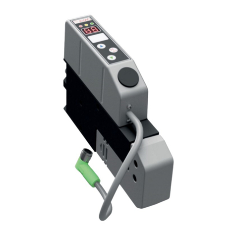
PIAB piPUMP 23 User manual

MANUAL
piPUMP 23
Original manual language is English.


English
CONTENTS
Features ................................................................................................4
Indended use and misuse......................................................................5
Overview................................................................................................6
Installation.............................................................................................11
Mounting...............................................................................................13
Maintenance.........................................................................................14
Technical data.......................................................................................18
piPUMP 23
3

English
FEATURES
►Flexible conguration options to perfectly match application needs.
►Congurable vacuum ejector based on COAX®technology with integrated controls.
►Optimized design for high reliability and fast cycle times.
piPUMP 23
4

English
INTENDED USE
►The product shall be used to evacuate air (non liquids) from a volume to create
vacuum for gripping, holding and processes
►The product can be used to blow air for surface cleaning and to remove vacuum
from a volume
►The product shall be used in environments within the product’s specications and
certications
►The product shall be installed in accordance to installation instructions
►The product shall be maintained in accordance to maintenance instructions
►Troubleshooting shall be conducted in accordance to manual instructions
►The safety instructions shall be followed
►For professional use only.
MISUSE
►Result from readily predictable human behavior.
►The product shall not be used to evacuate liquids.
►The product shall not be used to evacuate solid content without the use of lter.
►The product shall not be used in a fully closed compartment (non ventilated) if not
exhaust is piped away.
►The product shall not be used as stand alone safety system to fulll international
►lifting norms.
►The exhaust shall not be restricted or blocked.
►The vacuum and exhaust port shall not simultaneous be blocked when unit is
generating vacuum.
►The product shall not be used to create vacuum or blow for other purposes than
the intended use.
►Vacuum and exhaust air can cause severe injuries, keep hands, legs, hair and
eyes away from vacuum inlets and exhausts.
►Do not install or operate you product if damaged.
►Do not operate the product if compressed air line is not properly secured, loose
compressed air lines can cause severe injuries.
►Using compressed air pressure and/or electrical voltage outside specication can
cause severe damage due to performance loss.
►Blow-off functions or ejector exhaust shall not be used to pressurize sealed com
partments such as cylinders and/or tank-volumes.
piPUMP 23
5

English
1 channel
OVERVIEW
2a 2b 2c 2d
8
3b
3a
3c
3d
1
G
G
F
A
B
E
piPUMP 23
6

English
A
B
E
F
G
2 channels
2d
2c
2b
2a
8
1
3c
3d
piPUMP 23
7

English
A
B
E
G
FG
3a
3c
3c
3d
2d
2c
2b
2a
8
1
3-4 channel
piPUMP 23
8

English
Connections
Pos. Description Size
1 Compressed air Push-in: Ø6 / Ø1/4’’ / Ø8 (Ø5/16’’) /
Ø10 / Ø3/8”
2a Vacuum port (1-3 ports) Push-in: Ø10 / Ø3/8’’ / Ø12 / Ø1/2’’
Barb: Ø12 /Ø1/2’’
2b Vacuum port (1-3 ports) Push-in: Ø10 / Ø3/8’’ / Ø12 / Ø1/2’’
Barb: Ø12 /Ø1/2’’
2c Vacuum port (1-3 ports) Push-in: Ø8 (Ø5/16’’) / Ø10 / Ø3/8’’
2d Vacuum port Push-in: Ø10
3a Exhaust on top (top mounted silencer)
3b Exhaust on the side (integrated silencer/
topmounted silencer)
3c Central exhaust (no side mounted silencer)
3d Central exhaust, side mounted central
silencer
8 Sensing port Plugged / G1/8
Pos. Description Note
A Vacuum connection block
B Vacuum lter
E 1x COAX® cartridge / 2x COAX® cartridge
F Gable Exhaust on the side,G 3/4”
threads
G Side mounted silencer/ Top mounted silencer
piPUMP 23
9

English
Pneumatic diagrams
Note: Filter is optional
1. Compressed air, 2. Vacuum, 3. Exhaust
piPUMP 23
10

English
INSTALLATION
Pneumatic installation
piPUMP23 can be installed in any orientation. Ensure that the exhaust from the ejector is
not blocked. When connecting oil free compressed air and vacuum hoses to the unit, it is
important to choose proper pipe dimensions to prevent pressure drops. Avoid restrictive inner
diameters, long piping distances, sharp bends and small sized connections.
Pneumatic technical information (per channel)
Unit COAX®
SX12 SX42
x1 x2 x1 x2
Feed pressure, pump at opt. MPa [psi] 0.504
[73.2]
0.515
[74.7]
0.47
[68.2]
0.54
[78.3]
Feed pressure, nozzle at opt. MPa [psi] 0.5 [72.5] 0.43 [62.4]
Max vacuum at opt. pressure -kPa [-inHg] 85 [25] 90 [26.6]
Air consumption at opt. pressure Nl/s [scfm] 0.72
[1.52]
1.44
[3.05]
2.21
[4.68] 4.42 [9.36]
Max vacuum ow at opt. pressure Nl/s [scfm] 1.22
[2.58]
2.44
[5.16]
3.46
[7.33] 6.92 [14.7]
Flow, blow off at 0.5
MPa [72.5 psi]
No counter pressure
/ Counter pressure
0.1 MPa [14.5 psi]
Without hatch
Nl/s
[scfm]
0-4.8/0 [0-0.16/0] 0-5.6/0 [0-0.2/0]
With hatch, ABO 0-6.1/4.4 [0-
0.21/0.16]
0-6.7/4.3 [0-
0.24/0.15]
With hatch, PVH
WARNING! Do not install or operate your piPUMP 23 if damaged during
transport, handling or use. Damage may result in bursting and cause injury or
property damage.
Compressed air quality
Quality of the compressed air shall full the requirements in DIN ISO 8573-1 class 4.
piPUMP 23
11

English
Minimum recommended hose diameter, outer/inner diameter
Car-
tridge
Vacuum Compressed air
1 channel
Compressed air
2 channel
Compressed air
3-4 channel
mm Inches mm
Inches
mm
Inch-
es
mm Inches
SX12 8/6 5/16/1/4 6/4 1/4/5/32 8/6 5/16/1/4 2x 8/6 2x 3/8/5/16
SX12 x2 10/8 * 3/8/5/16 * 8/6 5/16/1/4 10/8 3/8/5/16 2x 10/8 2x 3/8/5/16
SX42 12/10 1/2/3/8 8/6 5/16/1/4 10/8 3/8/5/16 2x 10/8 2x 3/8/5/16
SX42 x2 12/10 * 1/2/3/8 * 10/8 3/8/5/16 12/10 1/2/3/8 2x 12/10 2x 1/2/3/8
*Recommended minimum dual fittings.
Minimum recommended hose diameters are valid for hose lengths up to 2m (6 ft). For longer lengths,
use larger hose diameters or multiple hoses to avoid reduced vacuum flow performance and the risk
for false vacuum signals from sensors/switches.
If 3-4 units are used in a manifold with a push-in, please use both compressed air supply ports
for optimum performance
Use hose clamps and or cable ties to avoid tension and damage to the hose and hose connectors
piPUMP 23
12

English
MOUNTING
Side mounting 1 channel
75
2.953"
16
0.630"
4
0.157"
25
0.984"
Ø
4
0.158"
2x
Ø
4.6
0.181"
2x
42
1.654"
63
2.48"
75
2.953"
5.2
0.2"
4x
5.2
0.2"
3x
63
2.48"
Ø
Ø
1 channel
2 channels
75
2.953"
Ø5.2
0.2"
4x
40
1.57"
42
1.654"
Ø5.2
0.2"
2x
piPUMP 23
13

English
MOUNTING
3-4 channels
Unit 3 channels 4 channels
Cmm
[in] 89 [3.50’’] 112 [4,4’’]
75
2.953"
Ø
5.2
0.205"
4x
111.5
4.390"
C
C
Ø
5.2
0.205"
2x
MAINTENANCE
Before installation and when maintaining the piPUMP23 check the product and attachment for
damages or wear (such as hoses, hose clamps, clips etc) and replace the damage or worn parts
as described in the maintenance section.
piPUMP 23
14

English
MAINTENANCE
Exploded view
Spare parts
Pos Art. No Description
10205487 Filter element FM23-50, 4 pcs-piCOMPACT®23/piPUMP 23
20205572 Filter holder kit FM23-50-piCOMPACT®23/piPUMP 23
30205573 Filter holder kit FM23L-50-piCOMPACT®23/piPUMP 23
40205484 Spare Part Kit-piCOMPACT®23/piPUMP 23
50207377 Spare Part Kit stacked-piCOMPACT®23/piPUMP 23
70209028 Push-in connector 6 mm, EC20, 5 pcs
70209029 Push-in connector 1/4”, EC20, 5 pcs
70209030 Push-in connector 8 mm EC20, 5 pcs
70209031 Push-in connector 10 mm, EC20, 3 pcs
70209032 Push-in connector 3/8”, EC20, 3 pcs
70209033 Push-in connector 10 mm, EC30, 5 pcs
70209034 Push-in connector 3/8”, EC30, 5 pcs
70209035 Push-in connector 12 mm, EC30, 5 pcs
70209036 Push-in connector 1/2”, EC30, 5 pcs
60205575 COAX®cartridge SX12
60205724 COAX®cartridge SX42
4x
7
6
7
4
23
1
2x
5
piPUMP 23
15

English
5. Place the new lter in the lter holder
and place the lter holder in its position on
the pump and tighten the screw again.
Replacement of piPUMP 23 filter(s)
1. Release screw on top of lter to re-
lease lter holder and lter.
2. Lift up lter holder and lter.
3. Release the screw completely to
remove old lter from lter holder.
4. When the lter is out, check that no
powder or dust is stuck inside lter base.
Note: If you have a piPUMP23 comprising
two lters, remove the two screws on top
of lter holder before changing lter.
piPUMP 23
16

English
Replacement of COAX®cartridge
1. Release screws on top of the chip house
and lift up the chip house.
2. Remove screws completely and remove
the chip plug and take out the COAX®
cartridges. Remove COAX®by carefully
using a small screwdriver or a pliers.
Avoid using any tool inside the COAX®
cartridge in order to remove it.
3. Replace the COAX®cartridges with new
COAX®cartridges and remount the chip
plug. Ensure COAX® o-rings are greased
before mounting of COAX®. Use Klüber-
synth UH1 14-151 or similar grease.
4. Remount the chip house and tighten
the screws.
Note: when your piPUMP 23 is congured with a top mounted silencer, remove the top
mounted silencer (three screws) before demounting the chip house.
70 Ncm
[99 in oz]
Max
piPUMP 23
17

English
TECHNICAL DATA
Pneumatic technical information
Unit COAX®
SX12 SX42
x1 x2 x1 x2
Feed pressure, pump at opt. MPa [psi] 0.504
[73.2]
0.515
[74.7]
0.47
[68.2]
0.54
[78.3]
Feed pressure, nozzle at opt. MPa [psi] 0.5 [72.5] 0.43 [62.4]
Max vacuum at opt. pressure -kPa [-inHg] 85 [25] 90 [26.6]
Air consumption at opt. pressure Nl/s [scfm] 0.72
[1.52]
1.44
[3.05]
2.21
[4.68] 4.42 [9.36]
Max vacuum ow at opt. pressure Nl/s [scfm] 1.22
[2.58]
2.44
[5.16]
3.46
[7.33] 6.92 [14.7]
Flow, blow off at 0.5
MPa [72.5 psi]
No counter pressure
/ Counter pressure
0.1 MPa [14.5 psi]
Without hatch
Nl/s
[scfm]
0-4.8/0 [0-0.16/0] 0-5.6/0 [0-0.2/0]
With hatch, ABO 0-6.1/4.4 [0-
0.21/0.16]
0-6.7/4.3 [0-
0.24/0.15]
With hatch, PVH
Other data / environmental data
Temperature range -10 - 50°C [14-122°F]
Air humidity % RH 35-85
Materials PA, NBR, SS, PP, PU, Brass, Al
Values specied are tested at:
Room temperature (20⁰C [68⁰F] ± 3⁰C [5.5⁰F]).
Standard atmosphere (101.3 [29.9 inHg] ± 1.0 kPa [0.3 inHg]).
Relative humidity 0-100%.
Compressed air quality, DIN ISO 8573-1 class 4.
piPUMP 23
18

English
• Wear ear protection
if you are working
closer than 2-3m from
the vacuum ejector in
operation.
(GB) Safety
(DK) Advarselsymboler
(DE) Warnsymbole
(ES) Señales de ad-
vertencia
(FR) Sécurité
(IT) Segnali di av-
vertenza
(NL) Waarschu-
wingssymbolen
(NO) Sikkerhet
(PT) Sinais Avisadores
(SE) Säkerhet
(FI) Varoitusmerkit
(ZH) 安全
(PL) Bezpieczeństwo
(RU)Безопасность
• Vacuum force
• Vakuumkraft
• Vakuumkraft
• Fuerza de vacío
• Force d’aspiration
• Potenza di aspirazione
• Vacuumkracht
• Vakuumkraft
• Vácuo ligado
• Vakuumkraft
• Siła ssania
• Voimakas imu
• Сила вакуума
• .真空吸力
• Exhaust
• Udblæs
• Abluft
• Aire procedente
• Evacuation de l’air
• Aria di scarico
• Uitlaatlucht
• Eksos
• Saida de ar
• Utblås
• Poistoilma
• Wylot
• Выхлоп
• 排气
• Unrestricted exhaust
• Forbudt blokere udblæs-
ningen
• Abluft nicht blockieren
• Prohibido bloquear la salida
del aire
• Interdit de bloquer l´évacua-
tion de l´air
• Lo scarico della pompa non
deve
• essere ostruito
• Pompuitlaat vrijhouden
• Forbudt å blokkere eksos
• O escape da bomba deve
ser livre
• Förbjudet blockera utblås
• Ulospuhalluksen esto
kielletty
• Nieograniczony wylot
• Неограниченный выхлоп
• 自由排气
WARNING! Do not install or operate your piPUMP 23 if damaged
during transport, handling or use. Damage may result in bursting and
cause injury or property damage.
piPUMP 23
19

Original manual language is English.
No need to compromise
www.piab.com
Piab gives you service all over the world.
To find your local distributor, please visit www.piab.com
Art. No. 0210819_rev00
Piab AB, 2017-11
Table of contents
Other PIAB Water Pump manuals