Page 1.2 PXI BREADBOARD & PROTOTYPING MODULE 40-220A/225A
pickering
SECTION 1 - TECHNICAL SPECIFICATION
Breadboard/Prototype Module – 40-220A/225A
pickeringtest.com
Specifications
Operating/Storage Conditions
Operating Conditions
Operating Temperature:
Humidity:
Altitude:
0°C to +55°C
Up to 90% non-condensing
5000m
Storage and Transport Conditions
Storage Temperature:
Humidity:
Altitude:
-20°C to +75°C
Up to 90% non-condensing
15000m
PXI & CompactPCI Compliance
The module is compliant with the PXI Specication 2.2. Local Bus,
Trigger Bus and Star Trigger are not implemented.
Uses a 33MHz 32-bit backplane interface.
Safety & CE Compliance
All modules are fully CE compliant and meet applicable EU
directives: Low-voltage safety EN61010-1:2010, EMC Immunity
EN61326-1:2013, Emissions EN55011:2009+A1:2010.
Mechanical Characteristics
Single or dual slot 3U PXI (CompactPCI card).
3D models for all versions in a variety of popular le formats are
available on request.
Connectors
PXI bus via 32-bit P1/J1 backplane connector.
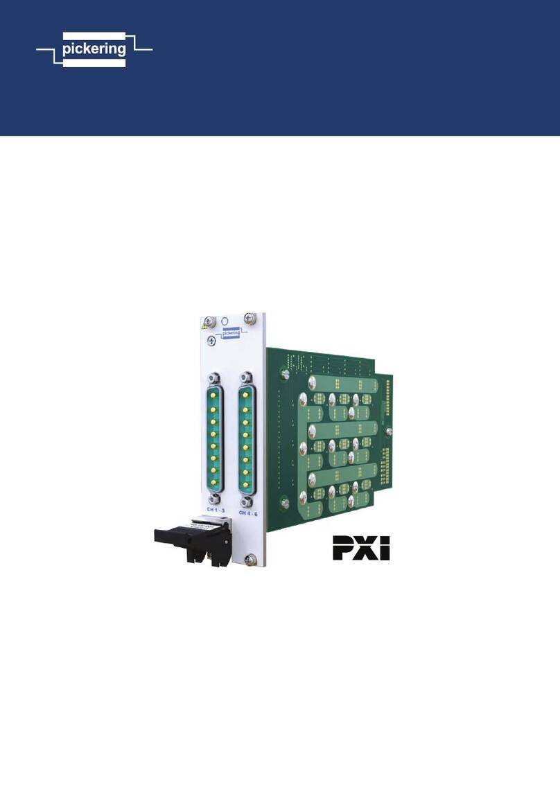
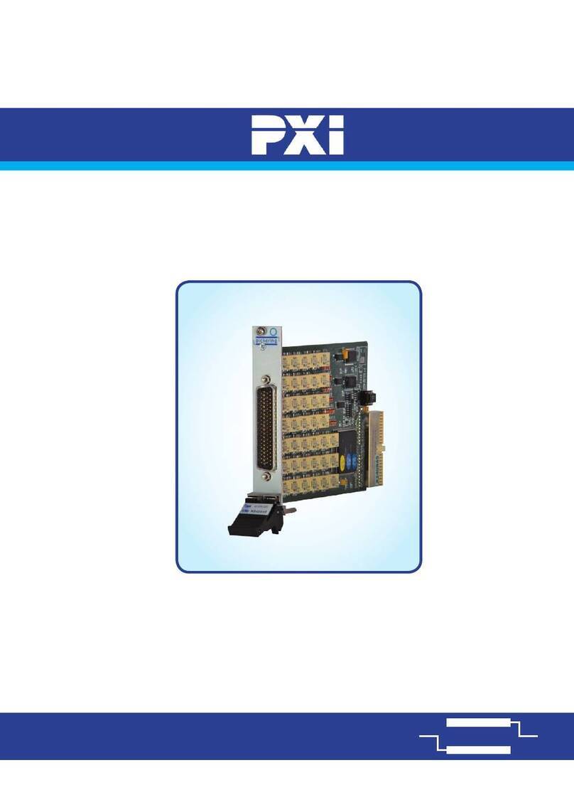
The 40-220A/225A is available with either a blank panel or a
selection of connector types.
Note: Care must be taken when interfacing the 40-220A module
with external circuits which may produce high voltage spikes or RF
interference. Additional noise protection may be required, please
contact Pickering if you wish to discuss your requirement.
40-225A PXI Prototype Module
The 40-255A is a “stripped down“ version of the 40-220A - a very
basic, low cost, prototype module. It has no PXI interface, but has
access to the PXI backplane power supplies via on-board fuses.
General Specification (40-220A)
TTL Output Driver
Maximum Drive:
Maximum Voltage:
Maximum Current Drive:
Operating Time:
15 TTL Inputs
7V*
Sink 8mA, Source 0.4mA
<10µs
Open Collector Transistor
Driver Device:
Maximum Standoff Volts:
Maximum Power per o/p:
Maximum Power per byte:
Maximum Current Drive:
Operating Time:
ULN2803LW O.C. driver
50V*
1.0W
1.6W
500mA
<10µs
Digital Input (All Models)
Maximum Standoff Volts:
Nominal True Voltage:
Maximum Power per byte:
7V*
>2.0V
<0.8V
Data is strobed when the read operation executes
* For full voltage rating, signal sources must be fully isolated from
mains supply and safety earth.
Connector Type Max Current Max Voltage
96-pin micro-D Plug
37-pin D-type Plug
25-pin D-type Plug
78-pin D-type Plug
50-pin D-type Plug
15-pin D-type Plug
9-pin D-type Plug
20-pin GMCT Plug
1A
5A
5A
3A
5A
5A
5A
13A
250V
500V
500V
250V
500V
500V
500V
500V
General Breadboard Details
Square pad and DIP construction areas. Approximately 652cm
(10 sq inches) of prototype area. 0.1” grid spacing.
Maximum Component Height:
Maximum Lead Length Below PCB:
Maximum Lead Diameter:
Maximum Voltage:
13mm (single slot)
33mm (dual slot)
1.52mm (dened by PXI)
0.7mm
300V*
Uncommitted Power Rails / Bus Lines:
Maximum Lead Diameter:
Maximum Current:
Maximum Voltage:
0.7mm
4A
300V*
* For full voltage rating, signal sources must be fully isolated from
mains supply and safety earth.
Power Supply
All four PXI system voltages are available (+3.3V, +5V & ±12V).
Up to 5A for +3.3V and +5V, and 1A for ±12V (within the limit of
the power supply). The power supplies are protected by on-board
fuses; 5A for +3.3V, 5A for +5V, and 1A for ±12V. Special versions
with supplies fused at 1A are available on request.
Power Requirements
Power consumption from the 5V backplane supply is as follows:
0.9W + 0.25W from User 5V.

