Page 1.1
USB DATA COMMUNICATIONS MULTIPLEXER MODULE 40-737
pickering SECTION 1 - TECHNICAL SPECIFICATION
SECTION 1 - TECHNICAL SPECIFICATION
pickeringtest.com
PXI USB Data Communications MUX 40-737
ISSUE 5.0 JUL 2018
Selected Builds Supported by
eBIRST
40-737 versions with a 78-pin D-type connector are supported
by eBIRST switching system test tools. These simplify switching
system fault-finding by quickly testing the system and
graphically identifying the faulty relay.
For more information go to: pickeringtest.com/ebirst
yMultiplexer Designed For Switching USB Signals
yConfigured As An 8:1 or a 16:1 Multiplexer
yWide Differential Bandwidth
yControlled Differential Impedance
ySuitable For USB1 and USB2 Switching
Applications
y8:1 Version Uses Standard USB Type A and B
Signal Connectors
yInterface Board Available For 16:1 Version
Allowing Use of Standard USB Cables
yVISA, IVI & Kernel Drivers Supplied for Windows
ySupported by PXI or LXI Chassis
ySelected Builds Supported by
eBIRST
™
y3 Year Warranty
All Data
Paths Are
Differential
Pairs
8 off USB Type A Connectors
USB Type B Connector
Out1 Data
Out2 Data
Out3 Data
Out4 Data
Out5 Data
Out6 Data
Out7 Data
Out8 Data
Out1 Vbus
Out2 Vbus
Out3 Vbus
Out4 Vbus
Out5 Vbus
Out6 Vbus
Out7 Vbus
Out8 Vbus
Out1 GND
Out2 GND
Out3 GND
Out4 GND
Out5 GND
Out6 GND
Out7 GND
Out8 GND
In Vbus
In GND
In Data
Switching diagram for the
40-737-901 8:1 USB Multiplexer
(relays are shown in their default position)
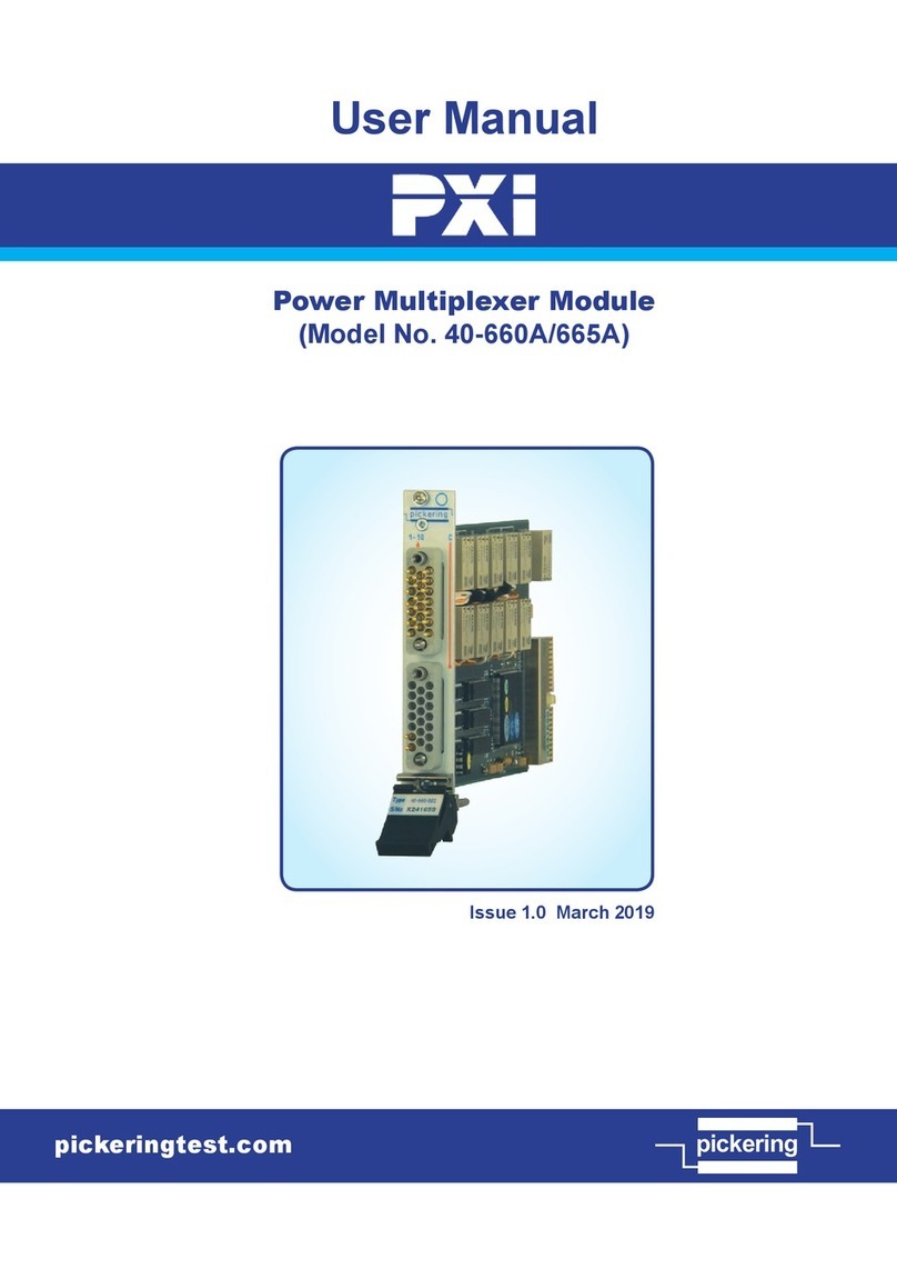
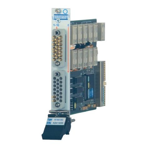
The 40-737 is an 8:1 or 16:1 multiplexer for switching data signals
and is specifically designed for routing USB. The data paths are
2-pole differential pairs as defined by the USB standard. The
multiplexer signal pairs have a controlled differential impedance
and the USB power paths have a common negative and a
switched positive. All paths are designed for minimum loss.
The common of the 8:1 multiplexer is via a front panel mounted
USB type B socket, and the eight channels are via USB type
A sockets. The 16:1 multiplexer has a male 78-pin D-type
connector for all signals and, using an interface board (40-965-
909), standard USB cables can be connected. Both multiplexer
versions are capable of switching USB1 or USB2.
The module is ideal for testing multiple USB devices, allowing
one target device to be selected from many. The design is
bi-directional allowing use as a multiplexer or de-multiplexer
with no impact on performance. Long life electro-mechanical
relays characterized for telephony are used.
Pickering’s Range of Data Comms Multiplexers
Model
No. Configuration Application
40-735 Single 36 channel or Dual 18
channel, differential pair USB, RS232
40-736 Single 32, Dual 16, Quad 8
channel, differential pair
1Gb Ethernet, AFDX,
BroadR-Reach, LVDS,
USB, RS232
40-737 Single 8:1 or 16:1 differential
pair and power USB1, USB2
