Picotest LoadSlammer Pro 1000 User manual

LoadSlammer™ Pro User Guide
User Guide for: LSP1000, LSP200, LSP40
Document 39011280
Rev 0.1

Document 39011280
05.27.2020 LoadSlammer Pro User Guide 1
1CONTENTS
2Introduction ............................................................................................................................ 2
2.1 Overview.......................................................................................................................... 2
2.2 Hardware......................................................................................................................... 2
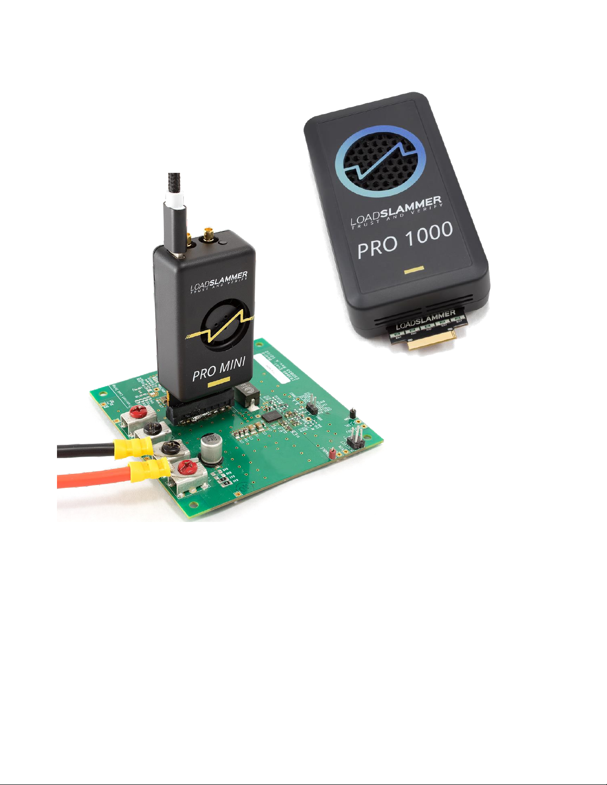
2.2.1 LoadSlammer Pro 1000........................................................................................... 2
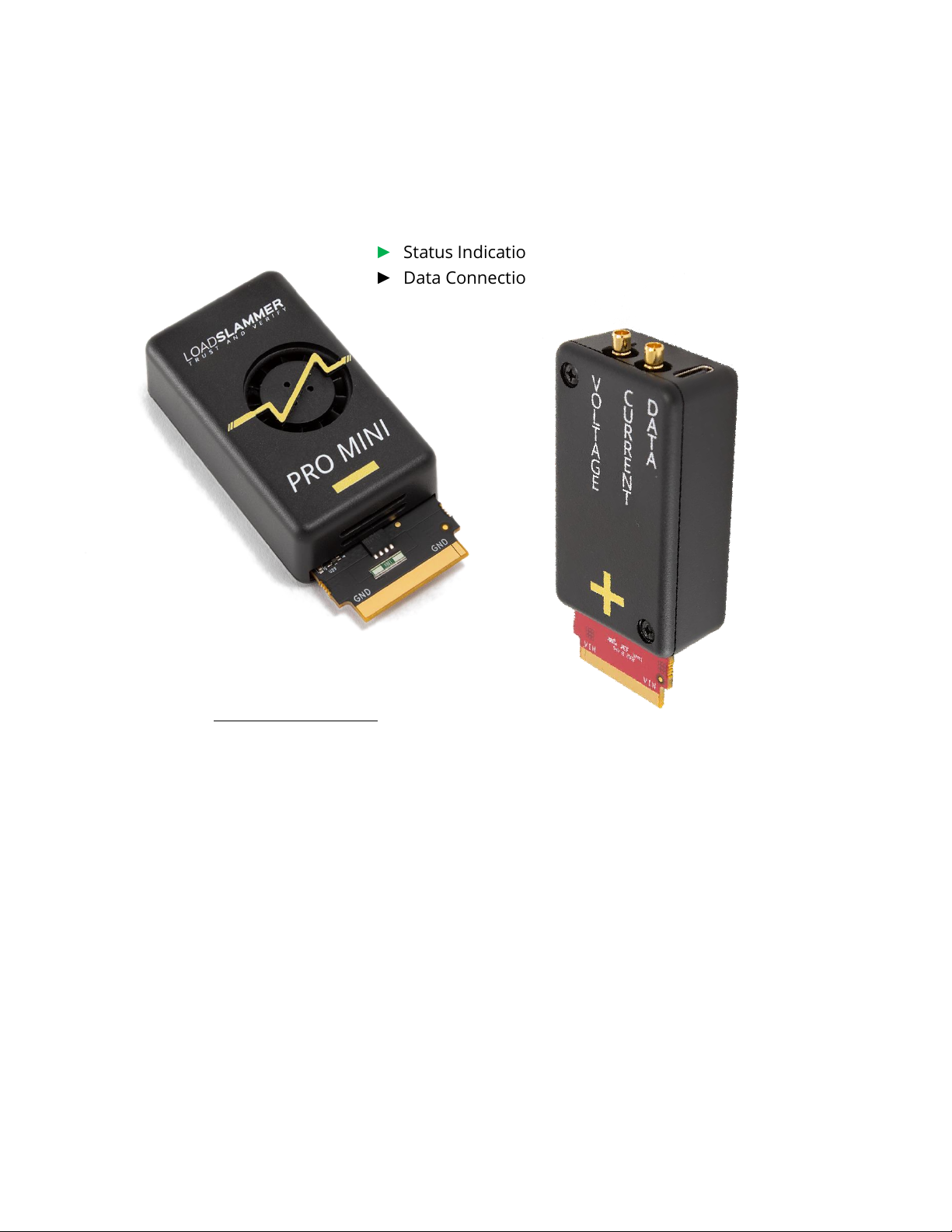
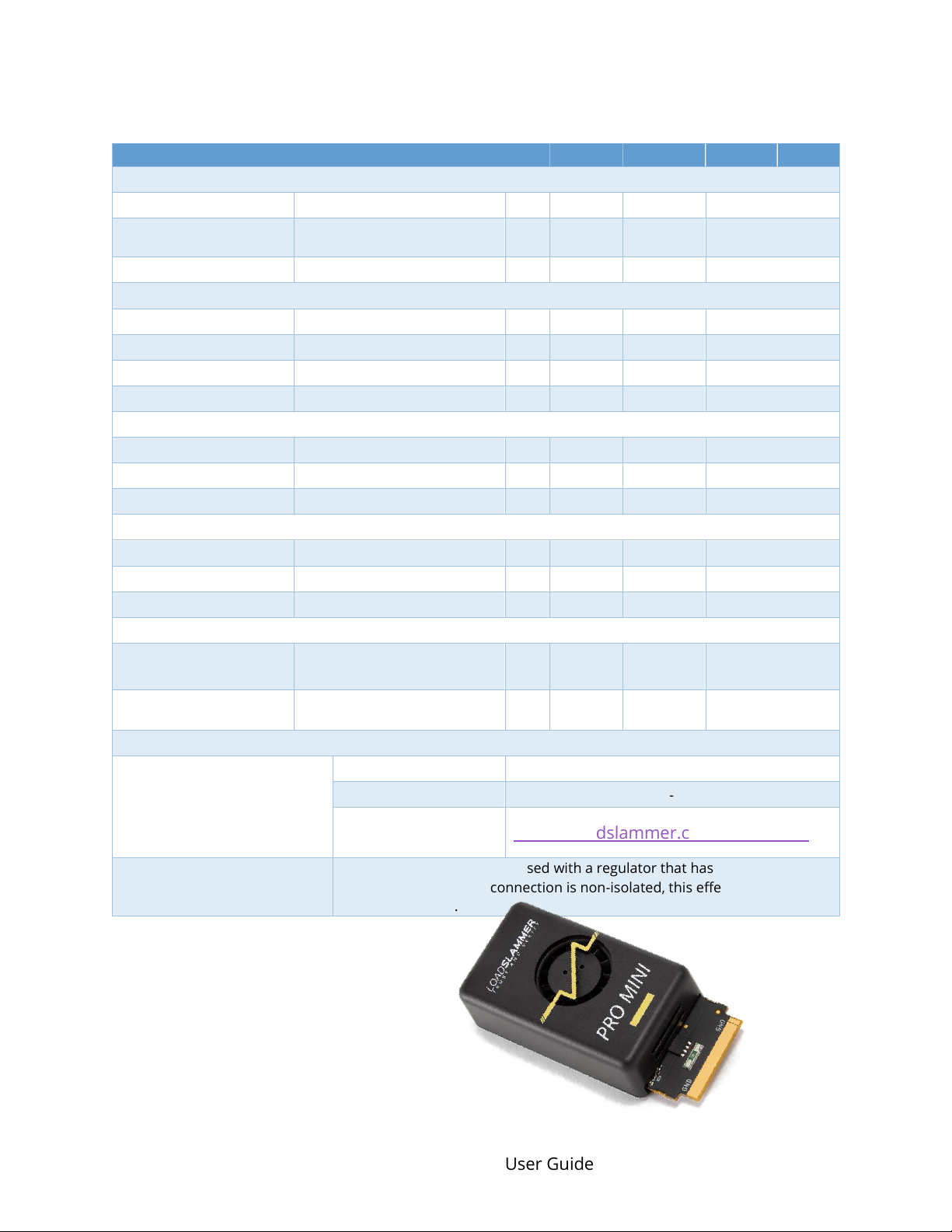
2.2.2 LoadSlammer Pro Mini............................................................................................ 3
2.3 Operating Specifications ................................................................................................ 4
2.3.1 LoadSlammer Pro 40............................................................................................... 4
2.3.2 LoadSlammer Pro 200............................................................................................. 5
2.3.3 LoadSlammer Pro 1000........................................................................................... 6
2.4 Terminology .................................................................................................................... 7
3Operating the LoadSlammer Pro.......................................................................................... 8
3.1 Physical Connection to DUT........................................................................................... 8
3.1.1 Placement Location ................................................................................................. 8
3.1.2 Connection Options................................................................................................. 8
3.1.3 Test Equipment Setup............................................................................................. 9
3.2 Connections to LoadSlammer ..................................................................................... 10
3.2.1 USB Data Connection ............................................................................................ 10
3.2.2 Voltage Sense......................................................................................................... 10
3.2.3 Current Sense ........................................................................................................ 10
3.2.4 Parallel.................................................................................................................... 10
3.3 Test Modes .................................................................................................................... 11
3.3.1 Transient ................................................................................................................ 11
3.3.2 Pulse Train.............................................................................................................. 11
3.3.3 Impedance ............................................................................................................. 12
3.3.4 Arbitrary ................................................................................................................. 12
3.3.5 Vender Specific ...................................................................................................... 12
4Change history...................................................................................................................... 13

Document 39011280
05.27.2020 LoadSlammer Pro User Guide 2
2INTRODUCTION
2.1 OVERVIEW
The LoadSlammer™ Pro is used to test fast, high current transient loads as seen in CPU,
GPU, FPGA, and ASIC power profiles. It is designed to be easy to use with a simple GUI,
voltage sense and current sense output. In addition to the sense outputs, the onboard
sampling and analysis allows for pass/fail testing all in one device.
2.2 HARDWARE
Hardware overview of the LoadSlammer Pro family.
2.2.1 LoadSlammer Pro 1000
►Current Monitor Output
►Voltage Monitor Output
►Status Indication LED
►Data Connection (USB Mini-B)
►Power Input (24V)
►Parallel Port
Included in the Box
•LSP1000 Device
•USB Mini-B Cable
•24V Power Adapter
•North American Power Cord

Document 39011280
05.27.2020 LoadSlammer Pro User Guide 3
2.2.2 LoadSlammer Pro Mini (200 & 40)
►Current Monitor Output
►Voltage Monitor Output
►Status Indication LED
►Data Connection (USB-C, USB 2.0)
Included in the Box
•LoadSlammer Pro Mini
•USB 2.0 type-A to type-C cable

Document 39011280
05.27.2020 LoadSlammer Pro User Guide 4
2.3 OPERATING SPECIFICATIONS
2.3.1 LoadSlammer Pro Mini 40
Table 1 –LSP40 Operating Characteristics
Parameter
Min
Typ.
Max
Unit
Timing Characteristics
Rise Time
180
200
89,000
nS
On Time Range
7.5µ
100m
Sec
Off Time Range
7.5µ
10
Sec
Load Characteristics
Current Range
1
20
A
Current Resolution
200
mA
Current Output Accuracy
5
%
Input Voltage Rating
0.6
2.0
V
Current Sense Output
Conversion Ratio
10
A/V
Max Current
20
A
Current Readout Accuracy
5
%
Sampling System
Sampling Rate
10
MSPS
Bandwidth
5
MHz
Capture Depth
24
kPoints
Power Dissipation Characteristics
Continuous Power
Dissipation
5
W
Instantaneous Power
Dissipation
100
W
Device Connection
DUT Connector
Preferred
Samtec HSEC8-130-01-L-DV-A-WT-K-TR
Surface Mount Only
Samtec HSEC8-130-01-L-DV-K-TR
Keepout Drawing and
Pinout
https://loadslammer.com/connector/
Non-Isolated
LoadSlammer Pro must be used with a regulator that has a positive voltage.
The USB data connection is non-isolated, this effectively grounds the DUT’s
ground.

Document 39011280
05.27.2020 LoadSlammer Pro User Guide 5
2.3.2 LoadSlammer Pro Mini 200
Table 2 –LSP200 Operating Characteristics
Parameter
Min
Typ.
Max
Unit
Timing Characteristics
Rise Time
180
200
89,000
nS
On Time Range
7.5µ
100m
Sec
Off Time Range
7.5µ
10
Sec
Load Characteristics
Current Range
5
100
A
Current Resolution
1
A
Current Output Accuracy
5
%
Input Voltage Rating
0.6
2.0
V
Current Sense Output
Conversion Ratio
50
A/V
Max Current
100
A
Current Readout
Accuracy
5
%
Sampling System
Sampling Rate
10
MSPS
Bandwidth
5
MHz
Capture Depth
24
kPoints
Power Dissipation Characteristics
Continuous Power
Dissipation
5
W
Instantaneous Power
Dissipation
100
W
Device Connection
DUT Connector
Preferred
Samtec HSEC8-130-01-L-DV-A-WT-K-TR
Surface Mount Only
Samtec HSEC8-130-01-L-DV-K-TR
Keepout Drawing and
Pinout
https://loadslammer.com/connector/
Non-Isolated
LoadSlammer Pro must be used with a regulator that has a positive
voltage. The USB data connection is non-isolated, this effectively grounds
the DUT’s ground.

Document 39011280
05.27.2020 LoadSlammer Pro User Guide 6
2.3.3 LoadSlammer Pro 1000
Table 2 –LSP1000 Operating Characteristics
Parameter
Min
Typ.
Max
Unit
Timing Characteristics
Rise Time
180
200
nS
On Time Range
7.5µ
100m
Sec
Off Time Range
7.5µ
10
Sec
Load Characteristics
Current Range
5
500
A
Current Resolution
1
A
Current Output
Accuracy
5
%
Input Voltage Rating
0.6
2.0
V
Current Sense Output
Conversion Ratio
50
250
A/V
Max Current
single device
500
A
Current Readout
Accuracy
5
%
Sampling System
Sampling Rate
10
MSPS
Bandwidth
5
MHz
Capture Depth
24
kPoints
Power Dissipation Characteristics
Continuous Power
Dissipation
25
W
Instantaneous
Power Dissipation
500
W
Device Connection
DUT Connector
Preferred
Samtec HSEC8-130-01-L-DV-A-WT-K-TR
Surface Mount
Only
Samtec HSEC8-130-01-L-DV-K-TR
Keepout Drawing
and Pinout
https://loadslammer.com/connector/
Non-Isolated
LoadSlammer Pro must be used with a regulator that has a positive voltage. The USB
data connection is non-isolated, this effectively grounds the DUT’s ground.

Document 39011280
05.27.2020 LoadSlammer Pro User Guide 7
2.4 TERMINOLOGY
Slew Rate –The change in current per unit of time (di/dt). Usually discussed in amps per
microsecond.
Rise Time –The time required for a signal to rise from 10% to 90% of the steady state
values.
Load Transient –A sudden change in load current.
Output Impedance –How well the DUT can maintain voltage regulation over frequency.
DUT (Device Under Test) –The DC-DC solution.

Document 39011280
05.27.2020 LoadSlammer Pro User Guide 8
3OPERATING THE LOADSLAMMER PRO
3.1 PHYSICAL CONNECTION TO DUT
3.1.1 Placement Location
Placement of the LoadSlammer Pro on the DUT (Device Under Test) is crucial. For
best results, place the LoadSlammer Pro as close to the load as possible to
include all the effects of the PDN. Placing the LoadSlammer Pro directly at the
output of the regulator does not adequately test the real-world application.
Do not connect the LoadSlammer Pro using wires. Wires increase the inductance of the
system which prevents high slew rates. The results will not be valid.
3.1.2 Connection Options
There are several ways to connect to a DUT. Using a connector provides ease of use and
reduces wear on the PCB but adds inductance and resistance to the power path. These
factors may limit your maximum slew rate. Soldering directly to the PCB helps minimize
inductance which can provide a cleaner signal and a faster slew rate. Additionally,
LoadSlammer offers custom passive adapter design services to provide a higher level of
confidence in the test results.
3.1.2.1
Design in Connector
The connector provides ease of use for quickly testing different DUTs.
Drawings are available on our website detailing pinout and keepout regions.
The preferred connector is the Samtec HSEC8-130-01-L-DV-A-WT-K-TR, however it does
require through holes. If design requirements prohibit through holes, there is a surface
mount only variant: Samtec HSEC8-130-01-L-DV-K-TR.
Due to the design of card edge connectors, the socket does not support the card rigidly.
There is a stabilizer accessory that prevents the device from tilting in the connector.
3.1.2.2
Solder Down
To solder the slammer to the DUT, find a large ground and power plane butting
up to each other, scrape some solder mask off, then solder it down with copper
braid. Alternatively, if your PCB has many ceramic capacitors in a row, it is
possible to solder directly on top of them.
Note: For optimal performance when using a connector, ensure that the LoadSlammer is firmly
seated and that the connector socket is clean. Failure to ensure a good connection can impact
your test results.

Document 39011280
05.27.2020 LoadSlammer Pro User Guide 9
3.1.2.3
Passive Adapter
Passive adapters are the best way to connect the LoadSlammer to a DUT. The adapter sits
in place of a large BGA package to allow connection of the LoadSlammer on an application
board. LoadSlammer offers custom passive adapter design services to provide a higher
level of confidence in the test results, from design reviews to turnkey development for your
application.
3.1.3 Test Equipment Setup
Use the following steps to get started with the LoadSlammer Pro:
1. Make sure DUT (Device Under Test) and LoadSlammer are both powered off
2. Install LoadSlammer unit onto DUT
Note: Make sure you observe proper polarity. The case has polarity
marked with “+” and “–“
3. Connect the USB cable from LoadSlammer to PC
4. (optional) Attach current & voltage monitoring of LoadSlammer to
oscilloscope using an SMB cable. Make sure the oscilloscope channels are
set to high input impedance
5. (LSP1000 only) Power on the LoadSlammer by plugging in the 24V power
adapter provided
6. Connect to the LoadSlammer though the GUI
7. Adjust test parameters to desired values
8. Hit the “Run” button to start slamming
3.1.3.1
Oscilloscope Connection
The current sense output on the LSP1000 has a gain that depends on the maximum
amount of current and power dissipation. The other LoadSlammer Pro devices have a
fixed current sense output gain.
Ensure the input impedance is set to 1MΩ or high impedance for both sense inputs. There
is a 50 ohm series termination resistor on the LoadSlammer. The current sense output has
an offset, so it should be zeroed out before taking measurements.
Download the GUI from: https://loadslammer.com/downloads/

Document 39011280
05.27.2020 LoadSlammer Pro User Guide 10
3.1.3.2
DC Measurements
While the LoadSlammer Pro has limited power dissipation, preventing efficiency
measurements, the LoadSlammer can create a ‘shoulder’ of current before each load
transient. This allows the DUT to settle to a steady state before the load transient.
An external DC load unit can be connected to the DUT if additional continuous power is
needed.
3.2 CONNECTIONS TO LOADSLAMMER
3.2.1 USB Data Connection
The LoadSlammer Pro Mini devices require only a USB 2.0 type-C connection; no external
power is required. The LoadSlammer Pro 1000 requires external 24V power in addition to
the USB 2.0 Mini-B connection.
3.2.2 Voltage Sense
The voltage sense output on the LoadSlammer
Pro is a passive single ended, 50 Ohm
transmission line. The transmission line is series
terminated, so ensure oscilloscope input is
setup as high-impedance input. Note the SMB
monitor is not differential. The voltage sense to
the LoadSlammer ADC is differential. If you
wish to measure hi di/dt voltage excursions with
an external oscilloscope you should measure
directly.
3.2.3 Current Sense
The current monitor output is derived from the current shunt. There is a fundamental L/R
time constant that limits the maximum bandwidth. For the LSP1000 and LSP200, the
maximum bandwidth is limited to approx. 750 kHz.
On the LSP1000, there are 5 parallel ‘channels’ with 5 current shunts summed together in
the analog domain.
3.2.4 Parallel
The LoadSlammer Pro 1000 supports the ability to parallel multiple devices to support very
high current requirements. A parallel cable is required to link the devices together.
To operate the devices in parallel, simply connected the parallel cable to each device.
Power all the devices through their respective DC barrel jack, then connect only one device
to USB (this will be referred to as the master device). With the GUI open, all the ‘slave’

Document 39011280
05.27.2020 LoadSlammer Pro User Guide 11
devices’ status indicator light will turn green indicating the device is in slave mode and
ready to test.
The voltage measurements are taken only from the master device.
3.3 TEST MODES
The LoadSlammer Pro family has several modes of operation and is field upgradeable to
offer additional functionality.
3.3.1 Transient
Transient mode is the most basic mode of operation. In this mode, the main goal is to
understand the step response of the DUT. A load transient is applied to the DUT to
determine the output voltage response. Some of the primary measurements are the
Droop and Liftoff amplitudes, and the recovery time of the regulator. Additionally, the load
line can be calculated, and the recovery response gives an indication of phase margin.
3.3.2 Pulse Train
Pulse Train mode is very similar to the transient mode. The main difference is the current
step from the transient pulse is modulated with a square wave to give a specific frequency
and duty cycle. This allows for the frequency and duty cycle to be swept over a range to
generate a 3D graph or frequency alone to look for resonant modes.
[Shot of Pulse Train]

Document 39011280
05.27.2020 LoadSlammer Pro User Guide 12
3.3.3 Impedance
Impedance mode applies a sinusoidal load transient and measures voltage amplitude to
determine the large signal impedance.
There are several ways to interpret this data. One way is to look at the amplitude response
of the voltage over frequency, known as output impedance. Complementary, analyzing the
spectral content at each applied frequency can inform on where the non-linarites of the
system are located.
The amplitude of the sin wave and the offset are set via the GUI. Determine the values to
sweep are based on target load currents, step sizes and PDN goals.
3.3.4 Arbitrary
Arbitrary mode lets the user configure a custom pattern. (Yet to be implemented).
3.3.5 Vender Specific
Vender specific tests are available upon request. Contact us at support@loadslammer.com.

Document 39011280
05.27.2020 LoadSlammer Pro User Guide 13
4CHANGE HISTORY
Revision Number
Date
Reason for change
0.1
May 27, 2020
Initial Release
This manual suits for next models
4
Table of contents
Other Picotest Test Equipment manuals