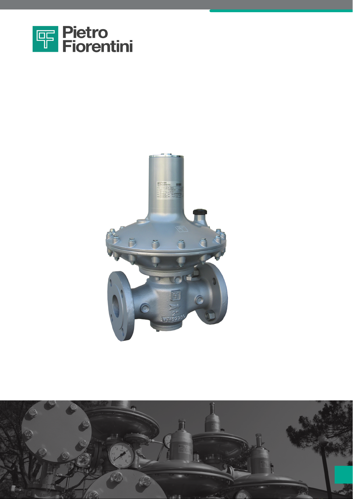
PIETRO FIORENTINI Dival 600 User manual

Dival 600
Revision A
EN
Medium-low pressure gas regulator
USE, MAINTENANCE
AND WARNING
INSTRUCTIONS EN

2
DIVAL 600
EN Use, maintenance and warning instructions
MEDIUM PRESSURE REGULATOR |INTRODUCTION |REV. A

3
DIVAL 600
Use, maintenance and warning instructions
MEDIUM PRESSURE REGULATOR |INTRODUCTION |REV. A EN
1 - INTRODUCTION
FOREWORD
All rights reserved. No part of this publication may be reproduced, distributed, translated into other languages or trans-
mitted by any electronic or mechanical media, including photocopies, recording or any other storage and retrieval system,
for any other purposes that are not exclusively the personal use of the buyer, without the express written permission of
the Manufacturer.
The manufacturer is in no way responsible for the consequences of operations carried out in a manner not in accordance
with the manual.
GENERAL REMARKS
All operating, maintenance instructions and recommendations described in this manual must be observed. In order to
obtain the best performance and to keep the equipment in efcient condition, the manufacturer recommends that main-
tenance operations be carried out regularly.
It is of particular importance that the personnel responsible for the equipment be trained in its use, maintenance and ap-
plication of the safety instructions and procedures indicated in this manual.
Revision: A
COPYRIGHT 2022
© PIETRO FIORENTINI S.P.A.

4
DIVAL 600
EN Use, maintenance and warning instructions
MEDIUM PRESSURE REGULATOR |INTRODUCTION |REV. A

5
DIVAL 600
Use, maintenance and warning instructions
MEDIUM PRESSURE REGULATOR |INTRODUCTION |REV. A EN
1.1 - REVISION HISTORY
Revision
index Date Revision contents
A10/2022
Tab. 1.1

6
DIVAL 600
EN Use, maintenance and warning instructions
MEDIUM PRESSURE REGULATOR |INTRODUCTION |REV. A
INDEX
1 - INTRODUCTION .................................................................................................................. 3
1.1 - REVISION HISTORY.................................................................................................................................. 5
2 - GENERAL INFORMATION ................................................................................................ 11
2.1 - MANUFACTURER IDENTIFICATION........................................................................................................ 11
2.2 - IDENTIFICATION OF THE PRODUCT ...................................................................................................... 11
2.3 - REGULATORY FRAMEWORK................................................................................................................. 11
2.4 - WARRANTY............................................................................................................................................ 11
2.5 - SYMBOLS USED IN THE MANUAL......................................................................................................... 12
2.6 - ADDRESSEES, SUPPLY AND STORAGE OF THE INSTRUCTION MANUAL........................................... 13
2.7 - LANGUAGE ............................................................................................................................................ 13
2.8 - NAMEPLATES APPLIED ......................................................................................................................... 14
2.8.1 - GLOSSARY FOR NAMEPLATES ...........................................................................................................15
2.9 - GLOSSARY OF UNITS OF MEASUREMENT........................................................................................... 16
2.10 -QUALIFIED PROFESSIONAL FIGURES................................................................................................... 17
3 - SAFETY .............................................................................................................................. 19
3.1 - GENERAL SAFETY WARNINGS.............................................................................................................. 19
3.2 - PERSONAL PROTECTIVE EQUIPMENT.................................................................................................. 20
3.3 - RESIDUAL RISKS ................................................................................................................................... 21
3.3.1 - TABLE SHOWING RESIDUAL RISKS DUE TO PRESSURE ...................................................................22
3.3.2 - TABLE OF RESIDUAL RISKS FOR POTENTIALLY EXPLOSIVE ATMOSPHERES ...................................24
3.4 - OBLIGATIONS AND PROHIBITIONS ....................................................................................................... 26
3.5 - SAFETY PICTOGRAMS .......................................................................................................................... 27
3.6 - RISK LEVEL ............................................................................................................................................ 27

7
DIVAL 600
Use, maintenance and warning instructions
MEDIUM PRESSURE REGULATOR |INTRODUCTION |REV. A EN
4 - DESCRIPTION AND OPERATION .................................................................................... 29
4.1 - GENERAL DESCRIPTION ....................................................................................................................... 29
4.1.1 - REGULATOR REACTION MODES.........................................................................................................30
4.2 - OPERATION............................................................................................................................................ 30
4.3 - INTENDED USE ...................................................................................................................................... 32
4.3.1 - ENVISAGED USE ..................................................................................................................................32
4.3.2 - REASONABLY FORESEEABLE MISUSE ...............................................................................................32
4.3.3 - TYPES OF FLUIDS ................................................................................................................................32
4.4 - TECHNICAL FEATURES/PERFORMANCE .............................................................................................. 33
4.5 - POSSIBLE CONFIGURATIONS ............................................................................................................... 34
4.5.1 - CONTROL HEADS................................................................................................................................34
4.5.2 - ACCESSORIES .....................................................................................................................................34
4.5.3 - REGULATOR WITH MONITOR FUNCTION............................................................................................36
4.5.4 - SLAM-SHUT VALVE ..............................................................................................................................39
4.5.4.1 - LA INCORPORATED SLAM-SHUT VALVE.....................................................................................40
5 - TRANSPORT AND HANDLING......................................................................................... 43
5.1 - SPECIFIC WARNINGS FOR TRANSPORT AND HANDLING ................................................................... 43
5.1.1 - PACKAGING AND FASTENERS USED FOR TRANSPORT ....................................................................44
5.2 - PHYSICAL CHARACTERISTICS OF THE EQUIPMENT ........................................................................... 46
5.2.1 - DIVAL 600.............................................................................................................................................46
5.2.2 - DIVAL 600 + LA.....................................................................................................................................47
5.3 - EQUIPMENT ANCHORING AND LIFTING METHOD................................................................................ 48
5.3.1 - FORKLIFT HANDLING METHOD...........................................................................................................49
5.3.2 - CRANE HANDLING METHOD...............................................................................................................51
5.4 - PACKAGING REMOVAL.......................................................................................................................... 52
5.4.1 - PACKAGING DISPOSAL .......................................................................................................................52
5.5 - STORAGE AND ENVIRONMENTAL CONDITIONS .................................................................................. 53
5.5.1 - PRE-INSTALLATION WARNINGS AFTER PROLONGED STORAGE ......................................................53

8
DIVAL 600
EN Use, maintenance and warning instructions
MEDIUM PRESSURE REGULATOR |INTRODUCTION |REV. A
6 - INSTALLATION .................................................................................................................. 55
6.1 - INSTALLATION PRE-REQUISITES........................................................................................................... 55
6.1.1 - ALLOWED ENVIRONMENTAL CONDITIONS.........................................................................................55
6.1.2 - CHECKS BEFORE INSTALLATION........................................................................................................56
6.2 - SPECIFIC SAFETY INSTRUCTIONS FOR THE INSTALLATION STEP ...................................................... 57
6.3 - GENERAL INFORMATION ON CONNECTIONS ...................................................................................... 58
6.4 - REGULATOR INSTALLATION POSITIONS............................................................................................... 59
6.5 - INSTALLATION PROCEDURES .............................................................................................................. 60
6.5.1 - EQUIPMENT INSTALLATION PROCEDURES ........................................................................................60
6.5.2 - CONNECTION OF THE SENSING LINES TO THE DOWNSTREAM PIPING...........................................60
6.6 - POST-INSTALLATION AND PRE-COMMISSIONING CHECKS ................................................................ 62
7 - COMMISSIONING/MAINTENANCE EQUIPMENT........................................................... 63
7.1 - LIST OF EQUIPMENT.............................................................................................................................. 63
7.2 - EQUIPMENT NEEDED FOR THE DIFFERENT CONFIGURATIONS .......................................................... 65
8 - COMMISSIONING ............................................................................................................. 67
8.1 - GENERAL WARNINGS ........................................................................................................................... 67
8.1.1 - SAFETY REQUIREMENTS FOR COMMISSIONING ...............................................................................67
8.2 - PRELIMINARY PROCEDURES FOR COMMISSIONING .......................................................................... 68
8.3 - PROPER COMMISSIONING CHECK ...................................................................................................... 69
8.4 - CALIBRATION OF EQUIPMENT AND ACCESSORIES INSTALLED.......................................................... 69
8.5 - REGULATOR COMMISSIONING PROCEDURE ..................................................................................... 70
8.6 - COMMISSIONING PROCEDURE OF REGULATION LINE: DIVAL 600 REGULATOR + DIVAL 600 REGULA-
TOR WITH IN LINE MONITOR FUNCTION .............................................................................................. 72
8.6.1 - PRESSURISING WITH EXTERNAL SOURCE.........................................................................................76
8.7 - COMMISSIONING PROCEDURE OF DIVAL 600 REGULATOR WITH LA SLAM-SHUT VALVE................. 78
8.7.1 - INTERNAL TIGHTNESS CHECK OF LA SLAM-SHUT VALVE.................................................................78
8.7.2 - COMMISSIONING OF THE DIVAL 600 REGULATOR WITH LA SLAM-SHUT VALVE..............................79
8.7.3 - PROCEDURE FOR CALIBRATING THE PRESSURE SWITCH FOR THE LA INCORPORATED SLAM-
SHUT VALVE .........................................................................................................................................82
8.8 - COMMISSIONING PROCEDURE OF REGULATION LINE: DIVAL 600 REGULATOR + DIVAL 600 REGULA-
TOR WITH IN LINE MONITOR + LA SLAM-SHUT VALVE FUNCTION
............................................................................................................................................................... 86
8.9 - DEVICE CALIBRATION............................................................................................................................ 90
8.9.1 - PRESSURE SWITCH CALIBRATION FOR THE LA SLAM-SHUT VALVE ...............................................90

9
DIVAL 600
Use, maintenance and warning instructions
MEDIUM PRESSURE REGULATOR |INTRODUCTION |REV. A EN
9 - MAINTENANCE AND FUNCTIONAL CHECKS................................................................ 91
9.1 - GENERAL WARNINGS ........................................................................................................................... 91
9.2 - PERIODICALLY CHECKING AND INSPECTING THE EQUIPMENT FOR PROPER OPERATION .............. 93
9.3 - ROUTINE MAINTENANCE ...................................................................................................................... 94
9.3.1 - GENERAL SAFETY WARNINGS............................................................................................................94
9.3.2 - REPLACEMENT FREQUENCY FOR COMPONENTS SUBJECT TO WEAR ...........................................95
9.4 - ROUTINE MAINTENANCE PROCEDURES.............................................................................................. 97
9.4.1 - TIGHTENING TORQUES ......................................................................................................................98
9.4.3 - REPLACING ELEMENTS SUBJECT TO WEAR AND ABRASION.........................................................105
9.4.5 - REGULATOR DIVAL 600 .....................................................................................................................106
9.4.8 - LA SLAM-SHUT VALVE .......................................................................................................................130
9.4.10 - PROCEDURE FOR RECOMMISSIONING AFTER MAINTENANCE ......................................................142
10 - TROUBLESHOOTING...................................................................................................... 143
10.1 -GENERAL WARNINGS ......................................................................................................................... 143
10.2 -OPERATOR QUALIFICATION SPECIFICATION...................................................................................... 144
10.3 -TROUBLESHOOTING PROCEDURES .................................................................................................. 144
10.4 -TROUBLESHOOTING TABLES ............................................................................................................. 145
10.4.1 - TROUBLESHOOTING DIVAL 600 REGULATOR ..................................................................................145
10.4.2 - LA SLAM-SHUT VALVE TROUBLESHOOTING....................................................................................145
11 - UNINSTALLATION AND DISPOSAL ............................................................................... 147
11.1 -GENERAL SAFETY WARNINGS............................................................................................................ 147
11.2 -QUALIFICATION OF THE OPERATORS IN CHARGE............................................................................. 147
11.3 -UNINSTALLATION................................................................................................................................. 147
11.4 -INFORMATION REQUIRED IN CASE OF RE-INSTALLATION................................................................. 147
11.5 -DISPOSAL INFORMATION.................................................................................................................... 148
12 - RECOMMENDED SPARE PARTS................................................................................... 149
12.1 -GENERAL WARNINGS ......................................................................................................................... 149
12.2 -HOW TO REQUEST SPARE PARTS...................................................................................................... 149
13 - CALIBRATION TABLES ................................................................................................... 151
13.1 -CALIBRATION TABLES ......................................................................................................................... 151

10
DIVAL 600
EN Use, maintenance and warning instructions
MEDIUM PRESSURE REGULATOR |INTRODUCTION |REV. A

11
DIVAL 600
Use, maintenance and warning instructions
MEDIUM PRESSURE REGULATOR |GENERAL INFORMATION |REV. A EN
2 - GENERAL INFORMATION
2.1 - MANUFACTURER IDENTIFICATION
Manufacturer PIETRO FIORENTINI S.P.A.
Address
Via Enrico Fermi, 8/10
36057 Arcugnano (VI) - ITALY
Tel. +39 0444 968511 Fax +39 0444 960468
www.orentini.com sales@orentini.com
Tab. 2.2
2.2 - IDENTIFICATION OF THE PRODUCT
Equipment MEDIUM PRESSURE REGULATOR
Model DIVAL 600
Tab. 2.3
2.3 - REGULATORY FRAMEWORK
PIETRO FIORENTINI S.P.A., with registered ofces in Arcugnano (Italy) - Via E. Fermi, 8/10, declares under its sole re-
sponsibility that the equipment of the DIVAL 600 series described in this manual is designed, manufactured, tested and
checked in compliance with the requirements of EN 334 standard on gas pressure regulators.
The equipment complies with the requirements of Directive 2014/68/EU ("Pressure Equipment Directive" PED). The as-
sessment procedure adopted is in accordance with module H1 as per Annex III of the Directive.
NOTICE!
The declaration of conformity in its original version is delivered together with the equipment and this oper-
ating and warning manual.
2.4 - WARRANTY
PIETRO FIORENTINI S.P.A. guarantees that the equipment was manufactured using the best materials, with high quality
workmanship, and complies with the quality requirements, specications and performance set out in the order.
The warranty shall be considered null and void and PIETRO FIORENTINI S.P.A. shall not be liable for any damage and/or
malfunctions:
• due to any acts or omissions of the purchaser or end-user, or any of their carriers, employees, agents, or any third
party or entity;
• in the event that the purchaser, or a third party, makes changes to the equipment supplied by PIETRO FIORENTINI S.P.A.
without the prior written approval of the latter;
• in the event of failure by the purchaser to comply with the instructions contained in this manual, as provided by
PIETRO FIORENTINI S.P.A.
NOTICE!
The warranty conditions are specied in the commercial contract.

12
DIVAL 600
EN Use, maintenance and warning instructions
MEDIUM PRESSURE REGULATOR |GENERAL INFORMATION |REV. A
2.5 - SYMBOLS USED IN THE MANUAL
Symbol Denition
Symbol used to identify important warnings for the safety of the operator and/or equipment.
Symbol used to identify information of particular importance in the instruction manual.
The information may also concern the safety of the personnel involved in using the equipment.
Obligation to consult the instruction manual/booklet.
Indicates a requirement for the personnel to refer to (and understand) the operating and warning
instructions of the machine before working with or on it.
Tab. 2.4
HAZARD!
Alerts to a hazard with a high level of risk, an imminent hazardous situation which, if not prevented, will
result in death or severe damage.
WARNING!
Alerts to a hazard with a medium level of risk, a potentially hazardous situation which, if not prevented,
may result in death or severe damage.
ATTENTION!
Alerts to a hazard with a low level of risk, a potentially hazardous situation which, if not prevented, could
result in minor or moderate damage.
NOTICE!
Alerts to specic warnings, directions or notes of particular concern, that are not related to physical injury,
as well as practices for which physical injury is not likely to occur.

13
DIVAL 600
Use, maintenance and warning instructions
MEDIUM PRESSURE REGULATOR |GENERAL INFORMATION |REV. A EN
2.6 - ADDRESSEES, SUPPLY AND STORAGE OF THE INSTRUCTION MANUAL
The instruction manual is intended for qualied technicians responsible for operating and managing the equipment
throughout its service life.
It contains the necessary information to properly use the equipment and keep its functional and qualitative characteristics
unchanged over time. All information and warnings for safe, correct use are also provided.
The instruction manual, as well as the declaration of conformity and/or test certicate, is an integral part of the equipment
and must always accompany it whenever it is moved or resold. It is up to the user to keep this documentation intact for
reference throughout the lifespan of the equipment.
WARNING!
Removing, rewriting or editing the pages of the manual and their contents is not allowed.
Keep the instruction manual near the equipment, in an accessible place known by all qualied technicians
involved in using and running it.
PIETRO FIORENTINI S.p.A. shall not be held liable for any damage to people, animals and property caused
by failure to adhere to the warnings and operating procedures described in this instruction manual.
2.7 - LANGUAGE
The original instruction manual was drawn up in Italian.
Any translations into additional languages are to be made from the original instruction manual.
HAZARD!
The Manufacturer is not responsible for any incomplete translations. If any inconsistency is found, please
refer to the text of the original manual.
If inconsistencies are found or the text does not make sense:
• stop any actions;
• immediately contact the relevant ofces of PIETRO FIORENTINI S.p.A.
WARNING!
PIETRO FIORENTINI S.p.A. shall be held liable for the information provided in the original manual only.

14
DIVAL 600
EN Use, maintenance and warning instructions
MEDIUM PRESSURE REGULATOR |GENERAL INFORMATION |REV. A
2.8 - NAMEPLATES APPLIED
WARNING!
Removing nameplates and/or replacing them with other plates is strictly not allowed.
Should the plates be unintentionally damaged or removed, the customer must notify
PIETRO FIORENTINI S.p.A.
The equipment and its accessories are provided with nameplates (from Id.1 to Id.2).
The nameplates specify identication details of the equipment and its accessories to be provided, if necessary, to
PIETRO FIORENTINI S.p.A.
“Tab. 2.5” shows the nameplates applied:
Id. Type Image
1
NAMEPLATE
REGULATOR (EC version)
AND REGULATOR WITH IN LINE
MONITOR FUNCTION
2NAMEPLATE
SLAM-SHUT VALVE
ARCUGNANO(VI) - ITALY
TRIPPING UNIT
S.n.
TS
Wdso
AG max
bar
AG min
Wdo
Wdsu
Wdu
bar
bar
bar
Tab. 2.5

15
DIVAL 600
Use, maintenance and warning instructions
MEDIUM PRESSURE REGULATOR |GENERAL INFORMATION |REV. A EN
2.8.1 - GLOSSARY FOR NAMEPLATES
The terms and abbreviations used on nameplates are described in “Tab. 2.6”:
Term Description
AC Accuracy class.
AG max Slam-shut valve accuracy class due to pressure increase.
“OPSO” (Overpressure shut-off).
AG min Slam-shut valve accuracy class due to pressure decrease.
”UPSO”(Underpressure shut off).
bpu Range of inlet pressure for which the regulator ensures a given accuracy class.
CE Marking certifying compliance with applicable European directives.
Cg Flow rate coefcient.
Class
Alphanumeric designation used for reference purposes related to a combination of mechanical
and dimensional characteristics for anges, in accordance with the relevant parts of EN 1759
series, which includes the word Class followed by a dimensionless whole number.
DN Nominal size of connections.
Fail safe mode Regulator reaction mode (Fail open or Fail close).
Flange Type of anged connections or type of connection thread.
Fluid Type of uid compatible with the equipment.
ID no. Number of the Notied Body participating in the conformity assessment of the equipment.
Pilot Pilot family.
PS Maximum permissible pressure for which the equipment was designed.
Pumax Maximum inlet pressure at which the regulator can operate continuously under specic condi-
tions.
REGULATOR Equipment family.
SG Shut-off pressure class.
Slam-shut device Slam-shut valve family.
S.n. Equipment serial number.
Strength type Strength class: Integral strength or differential strength (DS).
TPermissible temperature range (min. and max.) for which the equipment was designed.
Tripping unit Pressure switch family.
Type Accessory type and family.
Wd Full setpoint range that can be obtained from the regulator by adjusting and/or replacing certain
components (e.g. replacement of valve seat or control element, e.g. spring).
Wdo
Full setpoint range with regard to tripping caused by increased pressure in the pressure switch
incorporated in the slam-shut valve.
This range can be obtained by adjusting and/or replacing the components (for example, spring
or sensitive element).
Wds Full setpoint range that can be obtained from the regulator by adjusting but not replacing the
components.
Wdso
Full setpoint range with regard to tripping caused by increased pressure in the pressure switch
incorporated in the slam-shut valve.
This range can be obtained by adjusting but not replacing the components.
Wdu
Full setpoint range with regard to tripping caused by decreased pressure in the pressure switch
incorporated in the slam-shut valve.
This range can be obtained by adjusting and/or replacing the components (for example, spring
or sensitive element).

16
DIVAL 600
EN Use, maintenance and warning instructions
MEDIUM PRESSURE REGULATOR |GENERAL INFORMATION |REV. A
Term Description
Wdsu
Full setpoint range with regard to tripping caused by decreased pressure in the pressure switch
incorporated in the slam-shut valve.
This range can be obtained by adjusting but not replacing the components.
Tab. 2.6
2.9 - GLOSSARY OF UNITS OF MEASUREMENT
Type of measurement Unit of measurement Description
Volumetric ow rate Sm³/h Standard cubic metres per hour
Scfh Standard cubic feet per hour
Pressure
bar Unit of measurement in the CGS system
psi Pounds per square inch
“wc Water column inch
Pa Pascal
Temperature
°C Degree centigrade
°F Fahrenheit degree
K Kelvin
Tightening torque Nm Newton-metre
ft-lbs Foot per pound
Sound pressure dB Decibel
Other measures
V Volt
W Watt
ΩOhm
Tab. 2.7

17
DIVAL 600
Use, maintenance and warning instructions
MEDIUM PRESSURE REGULATOR |GENERAL INFORMATION |REV. A EN
2.10 - QUALIFIED PROFESSIONAL FIGURES
Qualied operators in charge of using and managing the equipment throughout its technical service life:
Professional gure Denition
Mechanical
maintenance techni-
cian
Qualied technician able to:
• perform preventive/corrective maintenance operations on all mechanical parts of the
equipment subject to maintenance or repair;
• access all device parts for visual inspection, equipment checks, adjustments and cali-
brations.
The maintenance mechanical technician is not authorised to operate on live electrical sys-
tems (if any).
Electrical
maintenance techni-
cian
Qualied technician able to:
• perform preventive/corrective maintenance operations on all electrical parts of the de-
vice subject to maintenance or repair;
• read wiring diagrams and check the correct functional cycle;
• perform adjustments and operate on electrical systems for maintenance, repair and
replacement of worn parts.
The electrical maintenance technician can operate in the presence of voltage inside electri-
cal panels, junction boxes, control equipment etc. only if he/she is deemed to be suitable
(S.P.).
For general requirements, refer to the IEC EN 50110-1:2014 standard.
Worker in charge of
transport,
handling,
unloading and place-
ment on site
Operator qualied to:
• use lifting equipment;
• handle materials and equipment.
The equipment must be lifted and handled strictly in accordance with the instructions pro-
vided by the manufacturer as well as the regulations in force at the place where the equip-
ment is installed.
Installer
Qualied operator able to:
• carry out all the operations necessary to properly install the equipment;
• perform all the operations necessary for the proper functioning of the equipment and
the system in safety.
User’s
technician
Technician trained and authorised to use and manage the equipment for the activities for
which it was supplied. They must:
• be able to perform all operations required to properly run the equipment and the sys-
tem, ensuring their own safety and that of any personnel on site;
• have proven experience in properly using the equipment similar to that described in this
instruction manual, and be trained, informed and instructed in this regard.
The technician may carry out maintenance only if authorised/qualied to do so.
Tab. 2.8

18
DIVAL 600
EN Use, maintenance and warning instructions
MEDIUM PRESSURE REGULATOR |GENERAL INFORMATION |REV. A

19
DIVAL 600
Use, maintenance and warning instructions
MEDIUM PRESSURE REGULATOR |SAFETY |REV. A EN
3 - SAFETY
3.1 - GENERAL SAFETY WARNINGS
WARNING!
The equipment described in this instruction manual is:
• a device subjected to pressure in pressurised systems;
• normally installed in systems carrying ammable gases (for example: natural gas).
WARNING!
If the gas used is a combustible gas, the installation area of the equipment is dened as a “danger zone”
as there are residual risks that potentially explosive atmospheres may be generated.
In “danger zones” and in close proximity thereto:
• there must not be any effective sources of ignition;
• smoking is not allowed.
ATTENTION!
Authorised operators must not carry out operations or services on their own initiative that do not fall with-
in their competence.
Never operate the equipment:
• while under the inuence of intoxicating substances such as alcohol;
• if you are using drugs that may lengthen reaction times.
NOTICE!
The employer must train and inform operators on how to behave during operations and on the equipment
to be used.
Before installation, commissioning or maintenance, operators must:
• take note of the safety regulations applicable to the place of installation they are working in;
• obtain the necessary permits to operate when required;
• wear the personal protective equipment required by the procedures described in this instruction manual:
• ensure that the required collective protective equipment and safety information are available in the area they are op-
erating in.

20
DIVAL 600
EN Use, maintenance and warning instructions
MEDIUM PRESSURE REGULATOR |SAFETY | REV. A
3.2 - PERSONAL PROTECTIVE EQUIPMENT
”Tab. 3.9” shows the personal protective equipment (PPE) and its description. An obligation is associated with each sym-
bol.
Personal protective equipment means any equipment intended to be worn by the worker in order to protect them against
one or several risks that are likely to threaten their safety or health during work.
For the operators in charge, depending on the type of work requested, the most appropriate PPE of the following will be
reported and must be used:
Symbol Meaning
Obligation to use safety or insulated gloves.
Indicates a requirement for the personnel to use safety or insulated gloves.
Obligation to use safety goggles.
Indicates a requirement for personnel to use protective goggles for eye protection.
Obligation to use safety shoes.
Indicates a requirement for the personnel to use accident-prevention safety shoes.
Obligation to use noise protection equipment.
Indicates a requirement for the personnel to use ear muffs or ear plugs to protect their hearing.
Obligation to wear protective clothing.
Indicates a requirement for the personnel to wear specic protective clothing.
Obligation to use a protective mask.
Indicates a requirement for the personnel to use respiratory masks in the event of a chemical
risk.
Obligation to use a protective helmet.
Indicates a requirement for the personnel to use protective helmets.
Obligation to wear high visibility vests.
Indicates a requirement for the personnel to use high visibility vests.
Tab. 3.9
WARNING!
Each licensed operator is obliged to:
• take care of his/her own health and safety and that of other people in the workplace who are affected
by his/her actions or omissions, in accordance with the training, instructions and equipment provided
by the employer;
• appropriately use the PPE made available;
• immediately report to the employer, the manager or the person in charge any deciencies in the equip-
ment and devices, as well as any dangerous conditions they may become aware of.
Other manuals for Dival 600
1
Table of contents
Other PIETRO FIORENTINI Industrial Equipment manuals
Popular Industrial Equipment manuals by other brands

ABB
ABB VD4 Series Installation and service instructions

Jäger
Jäger Z45-D160.02 S15AY manual

Orion
Orion SPECTRA MAX instruction manual

morse
morse KK Installation and maintenance instructions

INA
INA KUE Series Fitting and Maintenance Instructions

Grease Guardian
Grease Guardian GGX7 Installation operation & maintenance