PiezoDrive PD200 User manual

PD200 V6 Manual 1 Rev 1.2, Released, 05-02-2018
PD200 –Power Amplifier
Version 6
Manual and Specifications

PD200 V6 Manual 2 Rev 1.2, Released, 05-02-2018
Contents
1Introduction ...............................................................................................................................................3
2Warnings / Notes .......................................................................................................................................3
3Specifications .............................................................................................................................................4
4Output Voltage Range................................................................................................................................5
5Output Current...........................................................................................................................................5
6Voltage Limits.............................................................................................................................................5
7Pulse Current Option .................................................................................................................................6
8Power Bandwidth.......................................................................................................................................7
9Small Signal Bandwidth..............................................................................................................................9
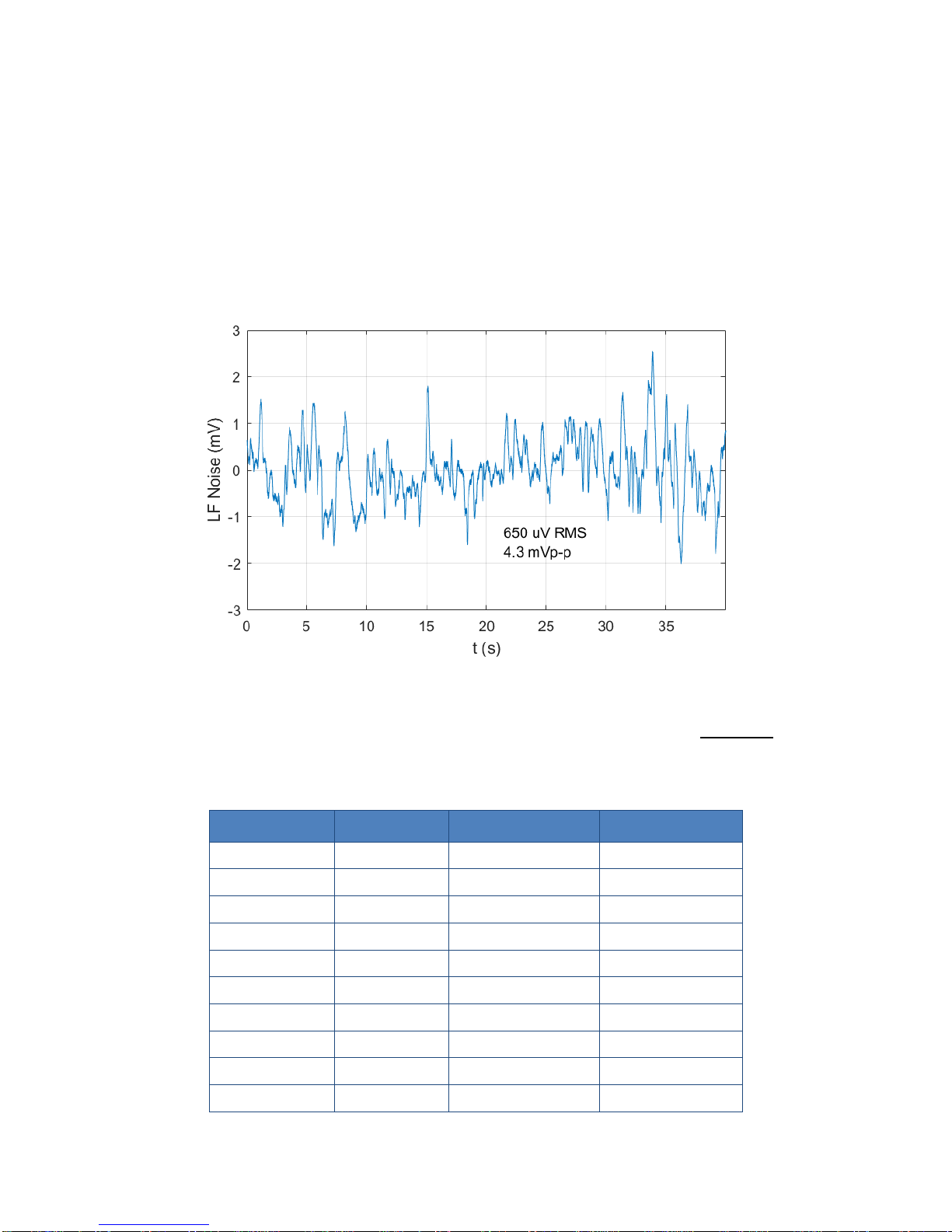
10 Noise ........................................................................................................................................................10
11 Front Panel...............................................................................................................................................11
12 Rear Panel ................................................................................................................................................12
13 Amplifier Configuration ...........................................................................................................................13
14 Bridged Mode ..........................................................................................................................................14
15 Overload and Shutdown ..........................................................................................................................15
16 Output Connections.................................................................................................................................15
16.1 HV Output Screw Terminals ..........................................................................................................15
16.2 LEMO OB Cable Assembly .............................................................................................................16
17 Enclosure..................................................................................................................................................17
18 Warranty ..................................................................................................................................................17

PD200 V6 Manual 3 Rev 1.2, Released, 05-02-2018
1Introduction
The PD200 is a high bandwidth, low noise linear amplifier for driving piezoelectric actuators. The output
voltage range can be unipolar, bipolar, or asymmetric from 50V to 200V. Up to +/-200V can be achieved in
the bridged configuration. The PD200 can drive any load impedance including unlimited capacitive loads
such as stack actuators; standard piezoelectric actuators; two wire benders; and three-wire piezoelectric
benders requiring a bias voltage.
Configuration options include the voltage range, polarity, and output current. The voltage range can also
be limited by two user-accessible potentiometers. The PD200 is suited to a wide range of applications
including electro-optics, ultrasound, vibration control, nanopositioning systems, and piezoelectric motors.
There are four output connectors including Lemo 00, Lemo 0B, BNC, and screw terminals that allow the
direct connection to almost any commercially available piezoelectric actuator. A rear-panel connector also
provides a temperature output, overload monitor, and external shutdown input.
Compatible Actuators
Stack Actuators
50V to 200V
Plates and Tubes
up to +/-100V
Two Wire Benders
up to +/-100V
Three Wire Benders
0 to 200V with 200V bias
Three Wire Benders
+/-100V with +/-100V bias
2Warnings / Notes
This device produces hazardous potentials and requires suitably qualified
personnel with an observer trained in first-aid training. Do not operate the
device when there are exposed conductors.

PD200 V6 Manual 4 Rev 1.2, Released, 05-02-2018
3Specifications
Electrical Specifications
Output Voltage Range
100 Vp-p
150 Vp-p
200 Vp-p
RMS Current
1.2 A
0.91 A
0.57 A
Pulse Current
10.0 A
10.0 A
10.0 A
Power Bandwidth
470 kHz
310 kHz
230 kHz
Gain
20 V/V
Slew Rate
150 V/us
Signal Bandwidth
680 kHz
Max Power
60 W Dissipation
Load
Any
Noise
714 uV RMS (10uF Load, 0.03 Hz to 1 MHz)
Protection
Continuous short-circuit, thermal
Voltage Monitor
1/20 V/V (BNC)
Current Monitor
1 V/A (BNC)
Analog Input
+/-10V (BNC, Zin = 27k)
Output Connectors
LEMO 0B, LEMO 00, Screw Terminals, BNC
Power Supply
90 Vac to 250 Vac
Mechanical Specifications
Environment
0-40 C (32-104 F) Non-condensing humidity
Dimensions
275 x 141 x 64 mm (10.8 x 5.5 x 2.5 in)
Weight
1 kg (2.2 lb)

PD200 V6 Manual 5 Rev 1.2, Released, 05-02-2018
4Output Voltage Range
The desired output voltage range is specified when ordering. The default output range is
0V to +200V (PD200-V0,200). The available voltage ranges and associated current limits are listed below.
Voltage Range
RMS Current
Peak Current
Order Code
0 to +200
0.57 A
2 A
PD200-V0,200
0 to +150
0.91 A
2 A
PD200-V0,150
0 to +100
1.20 A
2 A
PD200-V0,100
0 to +50
1.20 A
2 A
PD200-V0,50
-50 to +150
0.57 A
2 A
PD200-V50,150
-50 to +100
0.91 A
2 A
PD200-V50,100
-50 to +50
1.20 A
2 A
PD200-V50,50
-100 to +100
0.57 A
2 A
PD200-V100,100
-100 to +50
0.91 A
2 A
PD200-V100,50
Table 1. Voltage range configurations
5Output Current
The PD200 has a peak and average current limit as described in Table 1. The RMS current limit defines the
maximum frequency that is achievable with a capacitive load. This topic is discussed in “Power Bandwidth”.
During short-circuit the output current is limited to the rated maximum. The peak current can be drawn for
up to five milliseconds before the output is disabled for three seconds. The average current limit has a
time-constant of 30 milliseconds and is reset 100 milliseconds after a previous current pulse. This
behaviour is described in “Overload and Shutdown”.
6Voltage Limits
The output voltage range can be restricted to an arbitrary positive and negative value using two
potentiometers accessed from a pair of holes on the bottom panel. By gently turning the potentiometers
clockwise with a 2-mm flat-head screwdriver, the full voltage range becomes available. The voltage range is
reduced by turning the potentiometers anti-clockwise. The hole closest to the front panel controls the
negative voltage range while the rear hole controls the positive range.

PD200 V6 Manual 6 Rev 1.2, Released, 05-02-2018
7Pulse Current Option
For applications that require a high peak current, the peak current limit can be increased to 10 Amps by
appending the order code with “-PULSE”, e.g. “PD200-V0,200-PULSE”. In this configuration, the average
current limit remains the same; however, the peak current limit is increased to 8 Amps and the maximum
pulse duration is reduced to the time listed in Table 2. The voltage span is the peak-to-peak output voltage
range, e.g. the voltage span for the -50V to +150V range is 200V.
Voltage Span
Pulse Current
Pulse Time
200 V
10 A
100 us
150 V
10 A
150 us
100 V
10 A
400 us
50 V
10 A
400 us
Table 2. Maximum peak current duration in the pulse configuration
For a current pulse less than the peak current limit, the increased duration is described in Figure 1.
Figure 1. Maximum pulse duration versus peak current and voltage span

PD200 V6 Manual 7 Rev 1.2, Released, 05-02-2018
8Power Bandwidth
Launch Online Power Bandwidth Calculator
The online power bandwidth calculator takes into account the current limit, slew-rate,
output impedance, and small-signal bandwidth.
With a capacitive load, the RMS current for a sine-wave is
where
is the peak-to-peak output voltage, is the load capacitance and is the frequency. Therefore
the maximum frequency for a given RMS current limit capacitance, and voltage is
The above equation is also true for any periodic waveform, including triangle waves and square waves. This
property arises since the amplifier detects average current, which not affected by the waveform shape.
The ‘power bandwidth’ is the maximum frequency at full output voltage. When the amplifier output is
open-circuit, the power bandwidth is limited by the slew-rate; however, with a capacitive load, the
maximum frequency is limited by the RMS current and load capacitance. The power bandwidth for a range
of capacitive loads is listed below.
Load Capacitance
50V Range
100V Range
150V Range
200V Range
No Load
520 kHz**
470 kHz*
310 kHz*
230 kHz*
10 nF
520 kHz**
470 kHz*
270 kHz
130 kHz
30 nF
370 kHz
180 kHz
91 kHz
43 kHz
100 nF
110 kHz
56 kHz
27 kHz
13 kHz
300 nF
37 kHz
18 kHz
9.1 kHz
4.3 kHz
1 uF
11 KHz
5.6 kHz
2.7 kHz
1.3 kHz
3 uF
3.7 kHz
1.8 kHz
910 Hz
430 Hz
10 uF
1.1 kHz
560 Hz
270 Hz
130 Hz
Table 3. Power bandwidth versus load capacitance and output voltage span
In the above table, the frequencies limited by slew-rate are marked with an asterisk, and the frequencies
limited by small-signal bandwidth are marked with a double asterisk. The slew-rate is approximately
150 V/uS which implies a maximum frequency of
In the following figures, the maximum peak-to-peak voltage is plotted against frequency and capacitance.

PD200 V6 Manual 8 Rev 1.2, Released, 05-02-2018

PD200 V6 Manual 9 Rev 1.2, Released, 05-02-2018
9Small Signal Bandwidth
The small-signal frequency response and -3 dB bandwidth is described in Figure 3 and Table 4.
Figure 3. Small signal frequency response for a range of load capacitances.
Load Capacitance
Bandwidth
No Load
684 kHz
10 nF
759 kHz
30 nF
720 kHz
100 nF
388 kHz
300 nF
172 kHz
1 uF
60 kHz
3 uF
21 kHz
10 uF
6.4 kHz
30 uF
2.4 kHz
110 uF
940 Hz
Table 4. Small signal bandwidth versus load capacitance (-3dB)
103104105106
-10
0
10
20
30
40
Magnitude (dB)
103104105106
-200
-150
-100
-50
0
50
100
Phase (deg.)
Frequency (Hz)
Figure 2. Maximum peak-to-peak voltage versus frequency and load capacitance
300 nF
1 uF
3 uF
10 uF
30 uF
100 nF
30 nF
10 nF

PD200 V6 Manual 10 Rev 1.2, Released, 05-02-2018
10 Noise
The output noise contains a low frequency component (0.03 Hz to 20 Hz) that is independent of the load
capacitance; and a high frequency (20 Hz to 1 MHz) component that is approximately inversely
proportional to the load capacitance.
The noise is measured with an SR560 low-noise amplifier (Gain = 1000), oscilloscope, and Agilent 34461A
Voltmeter. The low-frequency noise is plotted in Figure 4. The RMS value is 650 uV with a peak-to-peak
voltage of 4.3 mV.
Figure 4. Low frequency noise from 0.03 Hz to 20 Hz
The high frequency noise (20 Hz to 1 MHz) is listed in the table below versus load capacitance. The total
RMS noise from 0.03 Hz to 1 MHz is found by summing the RMS values, that is
.
Load Cap.
Bandwidth
HF Noise RMS
Total Noise RMS
No Load
684 kHz
1.60 mV
1.72 mV
10 nF
759 kHz
1.65 mV
1.77 mV
30 nF
720 kHz
1.75 mV
1.86 mV
100 nF
388 kHz
2.08 mV
2.17 mV
300 nF
172 kHz
2.18 mV
2.27 mV
1 uF
60 kHz
998 uV
1.19 mV
3 uF
21 kHz
414 uV
771 uV
10 uF
6.4 kHz
295 uV
714 uV
30 uF
2.4 kHz
280 uV
708 uV
110 uF
940 Hz
264 uV
702 uV
Table 5. RMS noise versus load capacitance (0.03 Hz to 1 MHz)

PD200 V6 Manual 11 Rev 1.2, Released, 05-02-2018
11 Front Panel
Control
Type
Function
Power
Power On/Off
Offset
Adds a DC offset to the input signal
Input
Input
Input signal (+/-15V max)
Voltage Monitor
Output
The measured output voltage, scaled by 1/20
Current Monitor
Output
The measured output current, 1 A/V
Overload
RED when the amplifier is disabled or in an overload state
Power
GREEN when the power is on
HV-
Output
Connected to the negative high-voltage power supply rail
HV+
Output
Connected to the positive high-voltage power supply rail
Output-
Output
High-voltage output signal return (used to measure current)
Output+
Output
High-voltage output signal
LEMO 00 Output
Output
High-voltage output connector, suits LEMO FFA.00.250 cable plug
LEMO 0B Output
Output
High-voltage output connector, suits LEMO FGG.0B.302 cable plug
DC Output Volt.
Display showing average output voltage
The front panel connectors and recommended mating plugs are listed below.
Connector
Mating Connector
Manufacturer
PCB Component
BNC
Any BNC
4-Way Screw Terminal
TJ0631530000G
Amphenol
OQ0432510000G
LEMO 00
FFA.00.250
LEMO
EPL.00.250
LEMO 0B
FGG.0B.302
LEMO
EPG.0B.302
The LEMO 0B connector is recommended for applications requiring more than 1 Amp RMS output current.
Preassembled LEMO cable assemblies are available from www.PiezoDrive.com

PD200 V6 Manual 12 Rev 1.2, Released, 05-02-2018
12 Rear Panel
Control
Type
Function
Ground
Ground/Earth
Temp
Output
Internal heatsink temperature, 0.1 V/degree (Celsius)
Overload
Output
+5V output when the amplifier is disabled or in overload state
Disable
Input
A voltage from +3V to +24V disables the amplifier
The rear panel connector and recommended mating plug is listed below.
Connector
Mating Connector
Manufacturer
PCB Component
4-Way Screw Terminal
TJ0631530000G
Amphenol
OQ0432510000G

PD200 V6 Manual 13 Rev 1.2, Released, 05-02-2018
13 Amplifier Configuration
The amplifier can be configured with an inverting, or non-inverting input.
Amplifier Configuration
Order Code
Notes
Non-inverting
(default)
Inverting
-INV
Table 6. Amplifier configuration
The DC offset control is configurable with a positive range, or a bipolar range. The front panel
potentiometer can be disabled by enabling a PCB mounted trim-pot.
Offset Configuration
Order Code
Notes
0V to +200V Offset Range
(default)
+/-200V Offset Range
-OR2
Front panel source
(default)
PCB trim-pot source
-OS2
Disables front panel adjustment
Table 7. Offset configuration

PD200 V6 Manual 14 Rev 1.2, Released, 05-02-2018
14 Bridged Mode
In bridged mode, two amplifiers are connected in series to double the output voltage range and power.
For example, Figure 5 shows the configuration to obtain 200V across the load. A 5V signal applied to
both inputs produces 200V across the load. In bridged mode, only the Output+ terminal from each
amplifier is used, the negative output terminal is not connected. Since there is no current returning
through the negative terminal, the current monitor is disabled; however, the overload and protection
features are unaffected. Common bridged-mode configurations are listed in Table 8.
Figure 5. Bridge mode configuration for obtaining 200V
Load Voltage
RMS Current
Positive Amp
Negative Amp
+/-200V
0.57 A
PD200-V100,100
PD200-V100,100-INV
+/-100V
1.20 A
PD200-V50,50
PD200-V50,50-INV
Table 8. Common bridge-mode configurations
20
-20
Signal
Generator
+
5V
100V
100V
200V
Non-inverting
Inverting
Voltage across load
PD200-V100,100
PD200-V100,100-INV

PD200 V6 Manual 15 Rev 1.2, Released, 05-02-2018
15 Overload and Shutdown
The amplifier is protected against short-circuit, over-current, and excessive temperature. During these
conditions, the front panel overload indicator will illuminate and the rear-panel Overload signal is +5V.
During an overload or shutdown state, the output is disabled.
When the amplifier is switched on, the overload protection circuit is engaged by default and clears after
three seconds.
The amplifier can be shut down by an external source by applying a voltage of between +3V and +24V to
the Shutdown input on the rear panel. The impedance of the shutdown input is approximately 5 kΩ.
16 Output Connections
16.1 HV Output Screw Terminals
The screw terminal output has contacts for the output voltage, output return, and the internal HV supply
rails. The Output- signal is connected to ground through a 0.1 Ohm resistor.
Stack actuators are connected as shown below.
HV+
Output+
Output-
HV-

PD200 V6 Manual 16 Rev 1.2, Released, 05-02-2018
Bender actuators can be driven with a single bias voltage, for example 200 V, or a bipolar bias voltage, for
example ±100 V. The ±100 V bipolar configuration is shown below.
16.2 LEMO OB Cable Assembly
The LEMO 0B socket is the preferred output connector and is rated for 10 Amps RMS. The shield is directly
connected to ground, rather than Output-.
Preassembled LEMO cable assemblies are available from www.PiezoDrive.com
The recommended cable is Belden 8451. The recommended cable preparation is shown below for solder,
and crimp-terminal plugs.
Dimension
Solder Terminals
Crimp Terminals
L (Free Length)
13 mm
17 mm
S (Shield Length)
7 mm
7 mm
T (Strip Length)
3 mm
4 mm
The parts list for the LEMO 0B.302 plug are:
FGG.0B.302.CLAZ (solder terminals) or FGG.0B.302.CYCZ (crimp terminals)
FGG.0B.742.DN - collet for 3.1mm to 4mm cable
GMA.0B.035.DN - strain relief boot for 3.5mm to 3.9mm cable
The plug assembly process is:
1. Strip the cable as above
2. If the cable is shielded, fold the shield back over the cable
3. Slide the strain relief, collet nut (1) and collet (3) onto the cable.
4. Solder or crimp the conductors onto the contacts.
5. Assemble the plug, as shown below.
+200V
0 to 200V
0V

PD200 V6 Manual 17 Rev 1.2, Released, 05-02-2018
17 Enclosure
The enclosure has a side air intake and rear exhaust, which cannot be obstructed. If sufficient airflow is not
available, the amplifier will enter a thermal overload state as discussed in “Overload and Shutdown”.
The PD200 can be rack-mounted in a three channel arrangement as shown below. The order code is
PD200-Rack-X, where X is the number or populated channels (from 1 to 3).
18 Warranty
PiezoDrive amplifiers are guaranteed for 3 months. The warranty does not cover damage due to misuse.
Other manuals for PD200
1
Table of contents
Other PiezoDrive Amplifier manuals

PiezoDrive
PiezoDrive PD200 User manual

PiezoDrive
PiezoDrive PDUS200-PWR User manual

PiezoDrive
PiezoDrive PX200 User manual

PiezoDrive
PiezoDrive TD250 User manual

PiezoDrive
PiezoDrive PX200 User manual

PiezoDrive
PiezoDrive PD32 User manual

PiezoDrive
PiezoDrive TD250 V8 User manual

PiezoDrive
PiezoDrive PD200X4-V0,200 User manual

PiezoDrive
PiezoDrive PDUS210 User manual
Popular Amplifier manuals by other brands

Whest
Whest whestTHREE Phonostage Reference Series operating manual

DX Engineering
DX Engineering RPA-2 manual

Bogen
Bogen C10 Installation and use manual

Rockford Fosgate
Rockford Fosgate POWER 650 MOSFET owner's manual

Dynacord
Dynacord L Series installation manual

Episode
Episode EA-AMP-SUB-1D-110 owner's manual