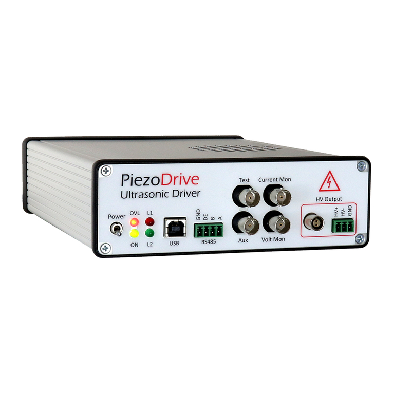
PiezoDrive PD200 User manual

1
PD200 – 60 Watt Voltage Amplifier
Manual and Specifications
PiezoDrivePty.Ltd.
www.piezodrive.com

2
Contents
1Introduction...................................................................................................................................3
2Warnings/Notes...........................................................................................................................3
3Specifications.................................................................................................................................4
4OutputVoltageRange....................................................................................................................5
5OutputCurrentRange....................................................................................................................5
6PowerBandwidth...........................................................................................................................6
7SmallSignalBandwidth..................................................................................................................8
8Noise..............................................................................................................................................9
9InputandOffsetConfiguration....................................................................................................10
10BridgedMode..............................................................................................................................11
11OverloadProtection.....................................................................................................................11
12OutputConnections.....................................................................................................................12
12.1ScrewTerminals.................................................................................................................12
12.2LEMOOBCablePreparation..............................................................................................13
12.3LEMOOBPlugAssembly....................................................................................................13
13Enclosure......................................................................................................................................14
14Warranty......................................................................................................................................14

3
1 Introduction
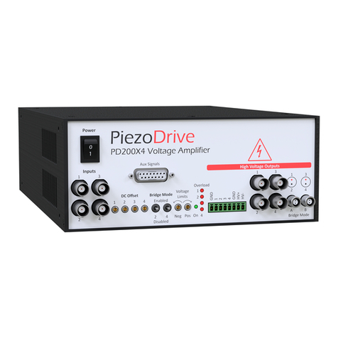
ThePD200isahighbandwidth,low‐noiselinearamplifierfordrivingpiezoelectricactuators.The
outputvoltagerangecanbeswitchedbetweenbipolarorunipolarmodeswitharangeof200V,
‐50Vto+150V,or±100V.Upto±200Vcanbeachievedinthebridgedconfiguration.
ThePD200candriveunlimitedcapacitiveloadssuchasstackactuators;standardpiezoelectric
actuators;twowirebenders;andthree‐wirepiezoelectricbendersrequiringa200Vbiasvoltage.
CompatibleActuators
StackActuators100V,120V,150V,200V
PlatesandTubesupto100V
TwoWireBendersupto100V
ThreeWireBenders0to200Vwith200Vbias
100Vwith100Vbias
ThePD200ishighlyuserconfigurablewithjumpersforoptionssuchasthevoltagerange,polarity,
andgaincontrol.Twopotentiometersarealsoprovidedtolimitthepositiveandnegativevoltages
toanyarbitraryvaluebetweenzeroandfullrange.Duetotheextensiveconfigurationoptions,the
PD200issuitedtoawiderangeofapplicationsincludingelectro‐optics,ultrasound,vibration
control,nanopositioningsystems,andpiezoelectricmotors.
TherearefouroutputconnectorsincludingLemo00,Lemo0B,BNC,andscrewterminalsthatallow
thedirectconnectiontoalmostanycommerciallyavailablepiezoelectricactuator,includingthose
fromPI,Piezomechanic,PiezoSystems,etc.
2 Warnings/Notes
Thisdeviceproduceshazardouspotentialsandshouldbeusedbysuitablyqualifiedpersonnel
underthesupervisionofanobserverwithappropriatefirst‐aidtraining.Donotoperatethedevice
whenthereareexposedconductors.
High-Voltage

4
3 Specifications
Electrical
OutputVoltageRanges+200V+150V ‐50to150V100V
RMSCurrent570mA
PeakCurrent2Ampsor10Amps
Gain20V/V
SlewRate150V/us
SignalBandwidth680kHz
PowerBandwidth230kHz(200Vp‐psine‐wave)
MaxPower 60WDissipation
Offset0VtoFullRangewithfrontpaneladjustment
LoadStablewithanyload
Noise665uVRMS(10uFLoad)
OverloadOver‐currentprotection
AnalogOutputsVoltagemonitor1/20V/V(BNC)
Currentmonitor1V/A(BNC)
AnalogInputSignalinput(BNC,=27k)
OutputConnectorsBNC,LEMO00,LEMO0B,
4mmBananaSockets
PowerSupply90Vacto250Vac
Mechanical
Environment 0to40C(32to104F)
Non‐condensinghumidity
Dimensions 275x141x64mm(10.8x5.5x2.5in)
Weight 1kg(2.2lb)

5
4 OutputVoltageRange
Theoutputvoltagerangecanbeconfiguredbydisconnectingtheamplifierfrommainspowerthen
removingthetoppanel.Thefollowingvoltagerangescanbeobtainedwiththecorrectcombination
ofinstalledjumpers.Notethatincorrectjumpersettingsmaydestroytheamplifier.
Thestandardoutputvoltagerangeis0Vto200V.However,theamplifiercanbesuppliedwithany
voltagerangebyappendingtheordercodewiththevoltagerangecode,forexample,thestandard
configurationisPD200‐V200.ThevoltagerangejumperlocationsarelabelledwiththeLP,LG,and
LNprefixesonthePCB.
VoltageRangeCodeLPLGLNLK10andLK12
0Vto+200‐V200LP1LG3 PositionA
0Vto+150‐V150LP2LG3 PositionA
0Vto+100‐V100LP2LG2 PositionA
0Vto+50‐V50LP2LG1 PositionA
‐50to+50‐V50,50LP2LG1LN1PositionB
‐50to+100‐V50,100LP2LG2LN2PositionB
‐50to+150‐V50,150LP1LG2LN2PositionB
‐100to+100‐V100,100LP1LG1LN2PositionB
Table 1. Voltage range configuration (Standard)
5 OutputCurrentRange
Thestandardpeakoutputcurrentis2Amps;however,forapplicationsthatrequireveryfaststep
changesinvoltage,theamplifiercanbeconfiguredinpulsemodewitha10Ampcurrentlimit.The
maximumpulsetimeforeachmodeislistedinTable2andplottedagainstcurrentinFigure1.
Theoutputcurrentrangecanbeconfiguredbydisconnectingtheamplifierfrommainspowerthen
removingthefrontandtoppanel.Theamplifiercanbesuppliedpreconfiguredtoanycurrentrange
byappendingtheordercodewiththecurrentrangecode,forexample,thestandardconfiguration
isPD200‐C2.
PeakCurrentCodePeakLimit OverloadTimerMaxPulseTime
2A‐C2LK16LK19andLK20Out1ms
10A‐C10LK18LK19andLK20Out100us
Table 2. Current range configuration (Standard)
6
Figure 1. Maximum pulse time versus current
6 PowerBandwidth
Withacapacitiveload,thepeakloadcurrentforasine‐waveis
whereisthepeak‐to‐peakoutputvoltage,istheloadcapacitanceandisthefrequency.
Givenapeakcurrentlimit,themaximumfrequencyistherefore
/.However,the
PX200isprotectedbybothpeakandaveragecurrentlimits.Theaveragecurrentisdefinedas
theaveragepositiveornegativecurrent.Forexample,forasine‐wave
1
2
sin
2
.
Therefore,forasine‐wave
/.SincetheaveragecurrentlimitofthePD200isfixedat
0.26A,themaximumfrequencysine‐wave,orpowerbandwidthofthePX200,isequalto
0.26
.
Theaboveresultistrueforanyperiodicwaveformsuchastriangularsignals.TheRMScurrentfora
sine‐wavecanalsoberelatedtotheaveragecurrent,
√2
.
Thepowerbandwidthsforarangeofloadcapacitancevaluesarelistedbelow.
0 2 4 6 8 10
0
0.5
1
1.5
2
2.5
3
3.5
4
Peak Current (A)
Max Pulse Duration (ms)

7
LoadPeaktoPeakVoltage
Cap.20015010050
NoLoad230kHz310kHz470kHz520kHz
10nF130kHz173kHz260kHz520kHz
30nF43kHz58kHz87kHz173kHz
100nF13kHz17kHz26kHz52kHz
300nF4.3kHz5.8kHz8.7kHz17kHz
1uF1.3kHz1.7kHz2.6kHz5.2kHz
3uF430Hz570Hz870Hz1.7kHz
10uF130Hz170Hz260Hz520Hz
30uF43Hz57Hz87Hz170Hz
Table 3. Power Bandwidth versus Load Capacitance
Intheabovetable,thefrequencieslimitedbyslew‐ratearemarkedingreenwhilethefrequencies
limitedbysignalbandwidtharemarkedinblue.Theslew‐rateisapproximately150V/uSwhich
impliesamaximumfrequencyof
15010
Inthefollowingfigure,themaximumfrequencyperiodicsignalisplottedagainstthepeak‐to‐peakvoltage.
Figure 2. Power bandwidth versus voltage and load capacitance
10
2
10
3
10
4
10
5
0
20
40
60
80
100
120
140
160
180
200
220
Frequency (Hz)
Peak to Peak Voltage (V)
300nF
1uF
3uF10uF30nF
100nF 10nF

8
7 SmallSignalBandwidth
Figure 3. Small signal frequency response.
LoadCap.Bandwidth
NoLoad684kHz
10nF759kHz
30nF720kHz
100nF388kHz
300nF172kHz
1uF60kHz
3uF21kHz
10uF6.4kHz
30uF2.4kHz
110uF940Hz
Figure 4. Small signal bandwidth versus load capacitance (-3dB)
103104105106
-10
0
10
20
30
40
Magnitude (dB)
103104105106
-200
-150
-100
-50
0
50
100
Phase (deg.)
Frequency (Hz)
300nF
1uF
3uF
10uF
30uF
100nF 30nF
1
0
nF

9
8 Noise
Theoutputnoisecontainsalowfrequencycomponent(0.03Hzto20Hz)thatisindependentofthe
loadcapacitance;andahighfrequencycomponent(20Hzto1MHz)thatisinverselyrelatedtothe
loadcapacitance.ManymanufacturersquoteonlytheACnoisemeasuredbyamultimeter(20Hz
to100kHz)whichisusuallyagrossunderestimate.
ThenoiseismeasuredwithanSR560low‐noiseamplifier(Gain=1000),oscilloscope,andAgilent
34461AVoltmeter.Thelow‐frequencynoiseisplottedinFigure5.TheRMSvalueis650uVwitha
peak‐to‐peakvoltageof4.3mV.Thenoiselevelisapproximatelyequaltotheleastsignificantbitof
a16‐bitdigital‐to‐analogconverter.
Figure 5. Low frequency noise from 0.03 Hz to 20 Hz. The RMS value is 650 uV, or 4.3 mVp-p.
Thehighfrequencynoise(20Hzto1MHz)islistedinthetablebelowversusloadcapacitance.The
totalnoisefrom0.03Hzto1MHzisfoundbysummingtheRMSvalues,thatis
.
LoadCap.BandwidthHFNoiseRMSTotalNoiseRMS
NoLoad684kHz240uV698uV
10nF759kHz241uV698uV
30nF720kHz243uV699uV
100nF388kHz234uV696uV
300nF172kHz171uV677uV
1uF60kHz133uV668uV
3uF21kHz115uV665uV
10uF6.4kHz112uV665uV
30uF2.4kHz98uV662uV
110uF940Hz85uV660uV
Table 4. RMS noise versus load capacitance (0.03 Hz to 1 MHz)
0 5 10 15 20 25 30 35 40
-3
-2
-1
0
1
2
3
t (s)
LF Noise (mV)

10
9 InputandOffsetConfiguration
Theinputstageisnormallynon‐inverting;however,itcanbeconfiguredasinvertingbychanging
LK14andLK15totheir“B”position.Thedefaultjumperpositionis“A”whichismarkedwitha
whitebaronPCBoverlay.Theamplifiercanbesuppliedwithaninvertinginputbyappendingthe
ordercodewith–INV.
InputConfigurationCodeLinkPositions
Non‐inverting(default)LK14andLK15Both“A”
Inverting‐INVLK14andLK15Both“B”
Table 5. Input polarity configuration
Theinputoffsetsourceisalsoconfigurable.WhenLK21isinthe“B”position,theoffsetisderived
fromtheon‐boardtrim‐potR15,whichisadjustablefromzerotofull‐scale.Thedefault
configurationforLK21isinthe“A”positionwheretheoffsetvoltageisderivedfromthefront‐panel
potentiometer.
Thestandardoffsetvoltagerangeisfromzerovoltstofull‐scale;however,forapplicationsthat
requirenegativeoffsetvoltages,LK13canbemovedfromthe“A”to“B”position.Inthe“B”
position,theoffsetrangeisfrom‐100Vtofull‐scale.
OffsetConfigurationCodeLinkPositions
0Vto+200VRange(def.)LK13“A”Position
‐100Vto+200VRange‐OR2LK13“B”Position
Frontpanelsource(def.)LK21“A”Position
PCBtrim‐potsource‐OS2LK21“B”Position
Table 6. Offset voltage source configuration

11
10 BridgedMode
Inbridgedmode,twoamplifiersareconnectedinseriestodoubletheoutputvoltagerangeand
power.Toobtain200Vattheload,theamplifiersareconfiguredasillustratedbelow.Both
amplifiersareconfiguredinthe100Vrangeandtheloweramplifierisalsoinverting.A5Vsignal
appliedtobothinputswilldevelop200Vattheoutput.
11 OverloadProtection
TheShutdownindicatorwillilluminateduringashutdowncausedbyanaveragecurrentoverload.
Duringshutdown,theamplifieroutputcurrentislimitedtoafewmAandmayfloattothehighor
lowvoltagerailiftheloadimpedanceishighorcapacitive.
Whentheamplifieristurnedon,theoverloadprotectioncircuitisengagedbydefaultandwilltake
approximatelythreesecondstoreset.
20
‐20
Signal
Generator
+
5V100V
100V
200V
Non‐inverting
Inverting
Voltageacrossload
PD200‐V100,100
PD200‐V100,100‐INV
Figure 6. Bridged configuration for obtaining +/-200 V

12
12 OutputConnections
AnactuatorcanbeconnectedtotheamplifierbyeitherscrewterminalsortheLEMO00,LEMO0B,
orBNCconnectors.Therecommendedconnectorsarelistedbelow.Thefullconnectorpartnumber
willdependonthediameterofthecableanddesiredstrainrelief.
OutputRecommendedConnectorManufacturer PCBConnector
BNCAnyBNCConnectorTE1‐1634613‐0
Terminals20020004‐D041B01LFFCI20020110‐D041A01LF
LEMO00FFA.00.250LEMOEPL.00.250
LEMO0BFGG.0B.302LEMOEPG.0B.302
Table 7. Output connectors
TheLEMO0Bconnectorisrecommendedinhighpowerapplications.PreassembledLEMOcable
assembliesareavailablefromwww.PiezoDriveOnline.com
12.1 ScrewTerminals
Theplug‐inscrewterminalhascontactsfortheoutputvoltage,ground,andthepositiveand
negativehigh‐voltagesupplyrails,whichareusefulwhendrivingpiezoelectricbenderactuators.
Benderactuatorscanbedrivenwithasinglebiasvoltage,forexample200V,orbipolarbias
voltages,forexample100V.The200Vunipolarconfigurationisillustratedbelow.
Ground
HV‐
HV+
Output
+200V
0to200V
0V

13
12.2 LEMOOBCablePreparation
(TakenfromLEMO0BSeriesCableAssemblyInstructions)
12.3 LEMOOBPlugAssembly
(TakenfromLEMO0BSeriesCableAssemblyInstructions)
1. Stripthecableasabove
2. Ifthecableisshielded,foldthe
shieldbackoverthecable
3. Slidethestrainrelief,colletnut(1)
andcollet(3)ontothecable.
4. Solderorcrimptheconductorsontothecontacts.
5. Assembletheplug,

14
13 Enclosure
ThePD200enclosurehasasideairintakeandrearexhaust.Theseventsshouldnotbeobstructed.
ThePD200amplifierscanberack‐mountedinathreechannelarrangementasshownbelow.The
rackpanel(19‐inchX2U)issuppliedseparatelyandrequiressomeuserassemblytomount
betweenoneandthreechannels.TherackordercodeisPD200‐RackPanel.
14 Warranty
PiezoDriveamplifiersareguaranteedforaperiodof3months.Thewarrantydoesnotcoverdamagedueto
misuseorincorrectuserconfigurationoftheamplifier.
Other manuals for PD200
1
Table of contents
Other PiezoDrive Amplifier manuals

PiezoDrive
PiezoDrive TD250 User manual

PiezoDrive
PiezoDrive PDUS210 User manual

PiezoDrive
PiezoDrive PX200 User manual

PiezoDrive
PiezoDrive PD200 User manual

PiezoDrive
PiezoDrive TD250 V8 User manual

PiezoDrive
PiezoDrive PD200X4-V0,200 User manual

PiezoDrive
PiezoDrive PD32 User manual

PiezoDrive
PiezoDrive PX200 User manual

PiezoDrive
PiezoDrive PDUS200-PWR User manual