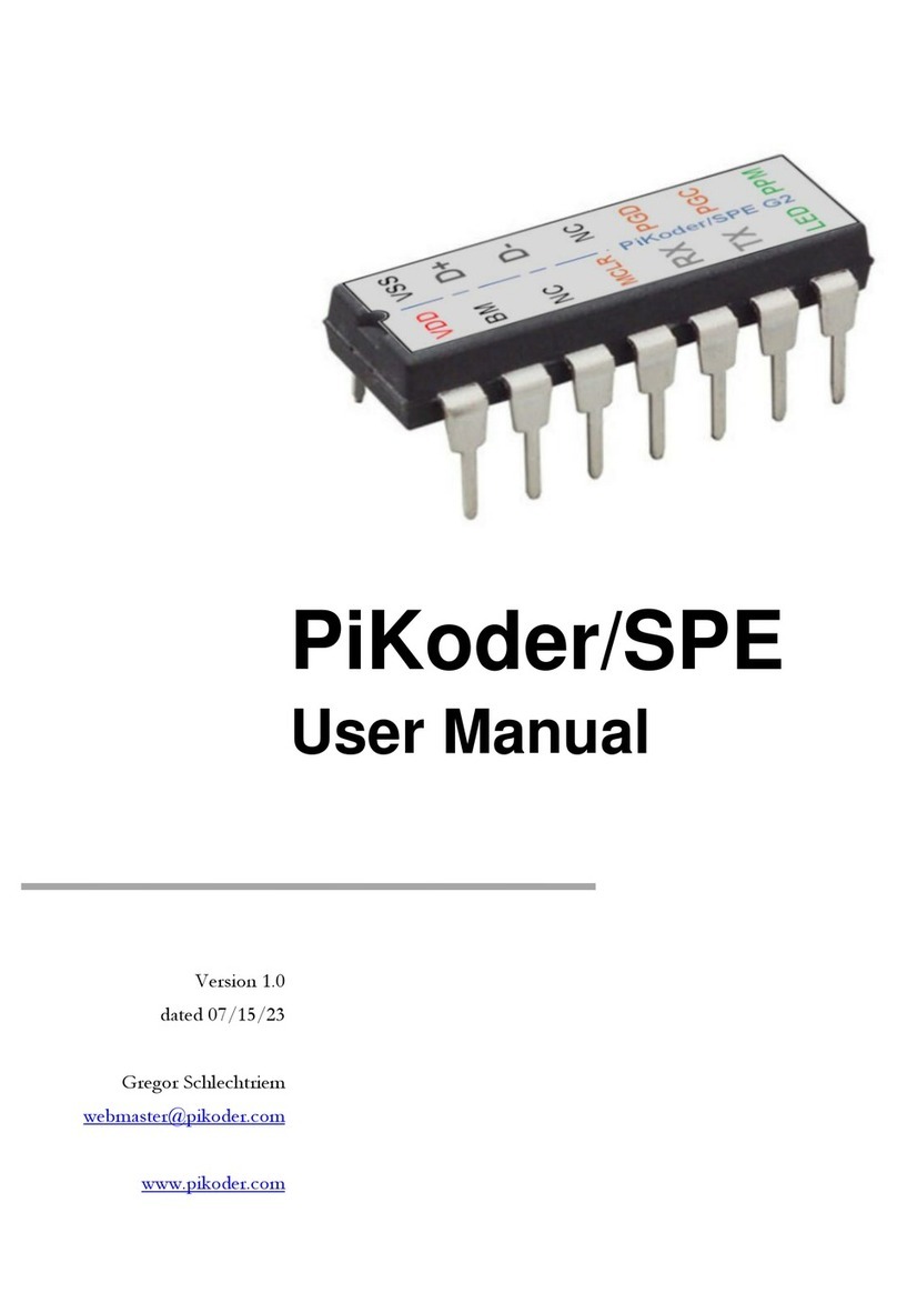
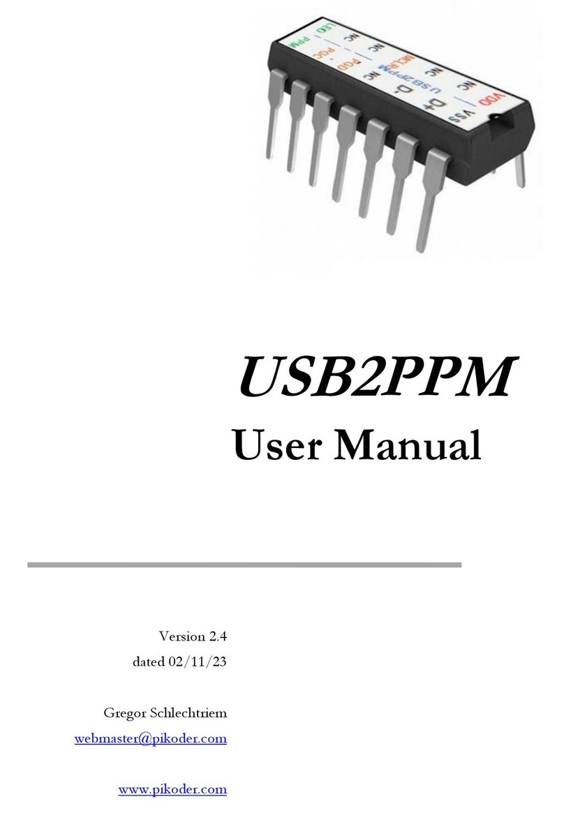
PIKODER UART2PPM Instructions for use

Construction manual PiKoder/SPE engineering board
ii
Table of Contents
Allgemeine Hinweise Fehler! Textmarke nicht definiert.
Bausatzumfang und Hilfsmittel Fehler! Textmarke nicht definiert.
Aufbau Fehler! Textmarke nicht definiert.
Bestückung der SMD Bauteile.............................................................................6
Test der Verbindungen der USB Buchse......................................................... 6
Bestückung des Kondensators C1.....................................................................7
Bestückung des Controllers...................................................................................8
Bestückung des Kondensators C2.....................................................................8
Bestückung der LED................................. Fehler! Textmarke nicht definiert.
Bestückung der Stiftleisten.................... Fehler! Textmarke nicht definiert.
Inbetriebnahme Fehler! Textmarke nicht definiert.
Anschlüsse Fehler! Textmarke nicht definiert.
Schaltung 15

3
1
HelpfulHints
Before you start the construction of your PiKoder/SPE, please review these in-
structions completely. Then you would know what matters and would avoid mis-
takes that will be hard to fix afterwards.
A basic understanding of electronic parts, their handling, and soldering (including
SMD components) is required for the construction and the commissioning of this
engineering board.
Conduct the soldering and the wiring in an orderly and conscientious manner; do
not use acidic solder of any kind. Make sure that there are no cold solder joints.
Keep these things in mind, because an unclean or bad joint, a defective contact or
a bad construction cause a time-consuming search for faults and could possibly
cause a destruction of the components.
You can significantly reduce the chance that something will not work. Check every
step before continuing. Follow the instructions! Only do the things written in the
manual and do not skip any steps! Check every step twice: once for building and
once to check.
Please take the time it needs to build this kit. Tinkering is not task work and should
be enjoyable!
Please share with me any errors, unclear instructions, or ideas for improvements.

4
2
Contentsofthe KitandToolsneeded
The kit in front of you contains all the necessary components needed to build a
PiKoder/SPE engineering board including the pre-programmed PIC16F1455.
Please verify the completeness with the help of the attached checklist.
Parts list: PiKoder/SPE
Resistors
√
47k, 0.25W (SMD)
R1
470R, 0.25W (SMD)
R2, R3
10k, 0.25W (SMD)
R4
2k7, 0.25W (SMD)
R5
Capacitors
100 n
C1
470n
C2
Semiconductors
PIC16F1455-I/P
IC1
LED 3mm bi-color
IC2
DO-214AC
D1
Misc.
Micro USB jack
J1
Header male 3 pins
PPM_OUT
Header male 4 pins
UART
Printed circuit board (pcb)

Engineering board PiKoder/SPE construction manual
5
You also need the following tools:
1. Electronic Soldering Iron
2. Electronic Solder
3. Side cutters
4. Multimeter
Additionally, to commission your board you will need:
1. USB cable
2. PC with PiKoder Control Center (PCC, downloaded from
www.pikoder.com)

6
3
Construction
The following paragraphs will describe how to populate the components on the
circuit board. The silk print on the circuit board will support this process. All parts
are populated on the top side. The order of the placement of the components
depends on their height; generally, you will place the lower first.
Placement of the SMD components
The first parts to assemble would be the SMD
components including the USB jack (SMD com-
ponent). Use a very fine soldering tip and small
diameter rosin core solder. Since all parts are
soldered at the top side, the order is not relevant.
Please pay attention the the position of the di-
ode: the line marking the cathode must be closer
to the right-hand pad (and thus closer to R5).

Engineering board PiKoder/SPE construction manual
7
Test step: Check USB connection
By far the most support requestes and
problem reports are linked to the USB
connection. And it is very difficult to
make any fixes or repairs once the con-
troller (IC) socket is placed.
Therefore, you should verify that the
first step was completed successfully.
Please connect your USB cable to the
pcb and verify the soldered connections
by using an ohmmeter: one probe
would be on the pcb pad and the other
would be used to contact the respective
metal connector of the USB cable.
Please refer to the image regarding the
four measurements to be made.
Populate the capacitor C1
Next, place the capacitor C1 followed by a mild
angling of the connection wires to prevent it from
falling out. The capacitor is non-polarized; there-
fore, the alignment is irrelevant.

Construction manual PiKoder/SPE engineering board
8
Populate the controller
Place the controller in the position indicated on
the top of the circuit board. Once again, verify
the positioning: the notch as indicated by the red
arrow.
To avoid the controller from falling out of its
position when turning the board slightly bend the
two outer diagonal pins and then go ahead and
solder all the other pins.
Populating the capacitor C2
Now, place the capacitor C2 into the respective
position followed by a mild angling of the con-
nection wires to prevent the pieces falling out.
This capacitor is also non-polarized meaning that
the alignment is irrelevant.

Engineering board PiKoder/SPE construction manual
9
Populate the LED
Place the LED. Please note that the LED is
polarized and that the shorter wire needs to be
on the left-hand side (see red arrow).
Populate the pin header
The last components you would solder on the
circuit board would be the pin headers for
PPM and UART.

Construction manual PiKoder/SPE engineering board
10

Engineering board PiKoder/SPE construction manual
11
4
Commissioning
Please start of by connecting your PiKoder/SPE engineering board with the USB
port of a Windows 10 computer. The PC will install the drivers needed upon the
initial connect. Once this step is completed, your board is ready for use.
If you wanted to program PiKoder/SPE settings, then please download the
PiKoder Control Center (PCC) form the PiKoder website.
You will find additional information regarding the use and the suitable parameter
values in the PiKoder/SPE User manual.

Construction manual PiKoder/SPE engineering board
12

13
A
Pinning
Please note: when powering the engineering board by USB, then +Vb would be
about 5 Volts –0.3 Volts (voltage drop diode). When powering the board via
UART pins, the board would work with 3.3 Volts to 5 Volts.

Construction manual PiKoder/SPE engineering board
14

15
B
Schematic
Table of contents
Other PIKODER Microcontroller manuals