PILLAR MACHINE H49 User manual

H49
USER MANUAL
PILLAR MACHINE, LLC
1810 W 5000 S
Salt Lake City, UT 84129
801-965-1900 | 800-369-5746

TABLE OF CONTENTS
Machine Specicaons
Safety Precauons
Inial Setup
Operang Procedures
Control Panel
The Glue / Water System
Dowel Length Adjustment
Seng X-Axis Backlash
Programming
Main Screen
Main Screen in Edit Mode
Maintenance Screen
Maintenance Schedule
Maintenance Tips
Diagram Glossary
Electrical Cabinet
Exploded Views
Horizontal Clamps
Glue Valve
Dowel Feed Bowl
Bowl Driver
Spare Parts List
Bowl Driver Instrucons
Motor RPM vs Hz Conversion Chart
Warranty

MACHINE SPECIFICATIONS
Model: H49
Voltage: 220 VAC 3 Phase
60 Hz 12 Amp
Air: 90 psi @ 20 CFM
Dust Collecon: 350 CFM
MATERIAL RESTRICTIONS
Work Piece Length………………………... Up to 49"
Work Piece Width…………………..….… Unlimited
Work Piece Thickness……….……....... Up to 1”
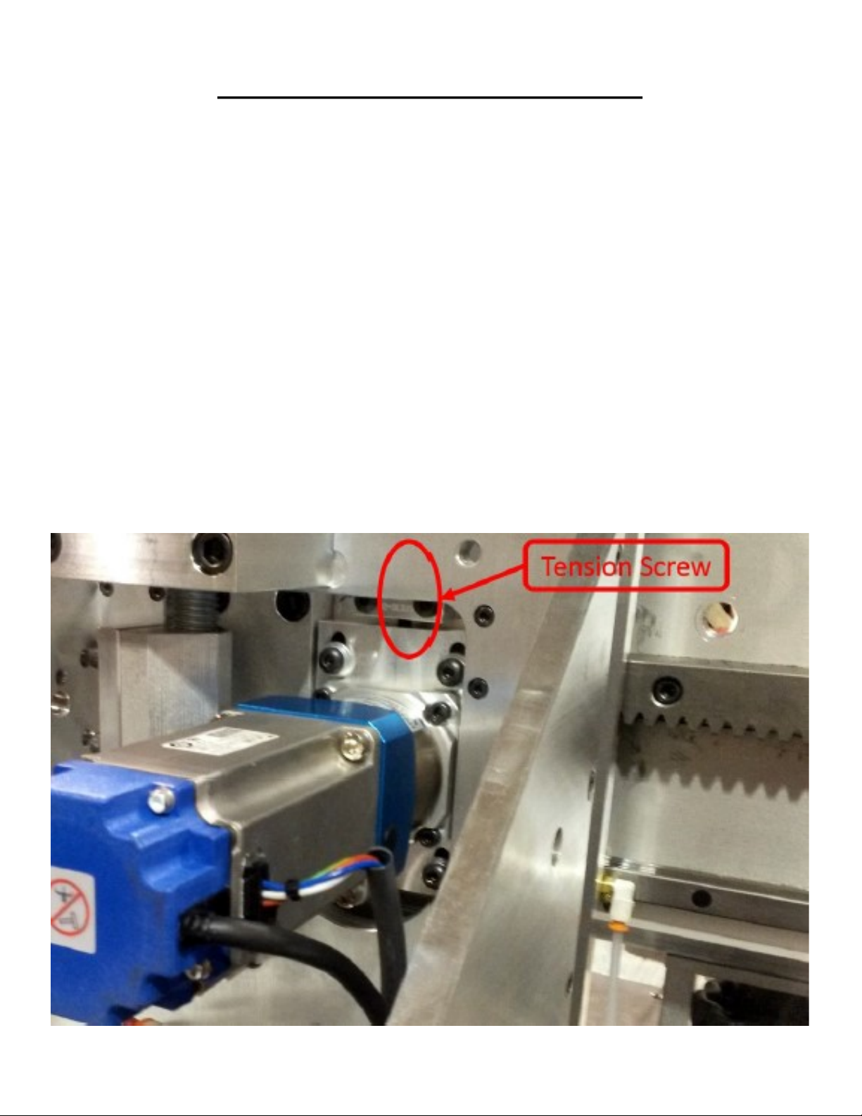
DRIVES
X Axis - Rack and inion
Y Axis - Mechanical by use of Digital Readou
Z Axis - Mechanical by use of Digital Readou
MACHINE DIMENSIONS
Length - 78” Depth - 52” Height - 76”
Weight 1400 lbs. (approximae)
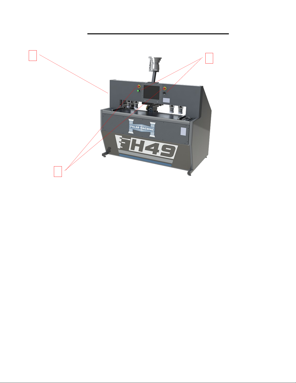
H-49 CNC HORIZONTAL POINT TO POINT MACHINING CNR
The model H-49 is a horizontal point to point bore and dowel inseron machining center. It is designed to CNC posion the spindle, bore a hole,
then CNC posion the inserter, inject glue or water (for pre glued dowels), and re the dowel into the hole. A part is placed into the work zone
referencing the back and side fences. The green palm buon is pressed and the clamps secure the part into place. The machining is now ready
to begin in the work zone. There are 2 zones standard in the base model H-49 allowing for pendulum processing. While the one part is being
machined, the other zone can be loaded and queued for machining.
SPINDLE CONFIGURATION
The machine is equipped with a 1 HP High Frequency 18,000 RPM Direct Drive Router Spindle mounted onto a 1/2" machined aluminum sur-
face. All wiring to the carriage is carried in an enclosed E Track to prevent damage to crical components. The 18,000 RPM spindle speed guar-
antees the boring bit concentricity, ensuring an accurate hole size for maximum glue contact. The high RPM also allows for rapid plunge boring
to be accomplished without losing the integrity of the boring surface. Pre-glued dowels can be used due to the accuracy and integrity of the
hole.
CLAMPS
The HP-49 comes standard with 4 quick adjust vercal clamps. Each clamp has 314 psi clamping force for maximum clamping capability.
GLUE INSERTER
The Glue Inserter is designed to accurately dispense glue into the hole in a predened metered amount. The glue nozzle is made of a self-
sealing nonsck Delrin material to allow for either glue or water to be used in the machine. It consists of an enclosed system using needle and
seat at valve, high pressure pump to 1,500 psi, with steel braided lines, innite adjustment to all valves.
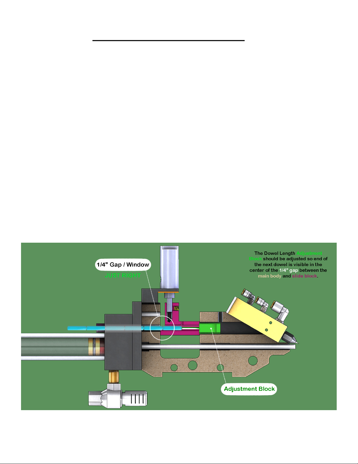
DOWEL INSERTER
Our patented dowel inseron system is a straight forward design. It has proven to reliably insert dowels without the need for realigned. Dowel
depth is set via a mechanical digital readout located on back of machine and is easily adjustable for dierent length dowels. The "Direct Reject
System" automacally detects an improperly sized dowel and noes the operator via the operator interface for dowel removal. The dowel
reject slide is opened, the dowel is removed, and then normal operaon is resumed.

SAFETY PRECAUTIONS
INITIAL SETUP
Please keep in mind these simple safety reminders when working on or around this ma-
Make all electrical connecons in accordance with local electrical code.
Disconnect power before servicing
Before opening or working in control panel, always turn o main power.
Always make sure power is o when changing drill bits or working around drill head.
Always wear safety glasses when running this machine
Always have hands clear from moving parts when operang machine.
Aer removing the outer crate, remove the plasc wrap covering the machine. Remove any blocks that are holding the machine
to the skid and carefully remove the machine from the skid.
You can fork from the front or back of the machine, just make sure the forks go far enough through to catch both the front and
back of the frame.
Place the machine into the general vicinity where it will be.
If necessary, level the machine using the 4 machine pads under each corner.
Install computer/touchscreen. See installaon procedures on the following page.
Connect the proper air supply. 3/8” diameter line is recommended.
The pressure should be 90-100 PSI @ 10-15 CFM to the machine.
Connect the proper power supply to the machine including grounding. 208/220 VAC 3 Phase.
Connect the proper dust collecon to the machine. (2 1/2” outlet)
Install the correct tooling.

OPERATION PROCEDURES
1
2
3
Control
1—Main Power Switch
The main power disconnect switch box is located on the le side of the machine near the air regulator. The lever must be in the
up, or ‘ON’ posion for the machine to operate.
2—Emergency Stop
The ‘E-stop’ buon is located in the center of the machine. Use this switch to stop the machine in an emergency. It will lock in
the down posion and the knob must be twisted to reset.
3—Zone Start Switches
The ‘Zone Start Switch’ is located above the fence of each zone and will begin the operaon of the machine if the ‘Program Run’
buon on the main screen has been acvated and a part is in posion in the respecve zone to be started. The ‘Zone Start
Switch’ buon will illuminate and stay illuminated unl the operaon has been carried out in that parcular zone, or the Emer-
gency Stop buon has been pushed. The H49 has two zone.

GLUE / WATER SYSTEM
Convenonal Dowels and Glue
Purging the System
Purge the glue valve before you use the machine to remove air in the system.
Prepare the glue pot.
Place glue in the glue pot. Make sure the pick-up tube goes into the glue when placing the lid back on the pot.
Tighten the pot lid down evenly. Now turn the pot pressure up to 20-30 PSI on the gauge.
Adjust glue pump pressure.
There is a glue pump with a regulator mounted on the side of the machine just above the pressure pot. Run the
glue pump at a pressure that will keep the glue owing properly. You do not need to use excessive pressure on
the system. Recommended glue pump pressure is around 70 PSI. Adjust air pressure to obtain desired amount
of glue ow. For water, the pump is not needed. Pot pressure set to 20 PSI is sucient.
Purge the System.
Place a small container under the clamp bar just in front of the nozzle. Press the purge buon located on the
main screen of the touchscreen. You should start to see glue coming out of the nozzle in about 2-3 seconds.
Run for 5 seconds to make sure the air is out of the line.
This is a sealed system and does not have to be ushed out aer each use.
Flushing the System
Flush the system with hot water once or twice a month, depending on use.
Remove the glue from the pot, clean the pot and ll a small container with hot water. Place the container in the pressure pot.
Place the pick-up tube in the container of water. Install lid and ghten the clamps.
The pressure should be set between 10-15 PSI since water is thinner than glue.
Place another small container under the clamp bar directly in front of the nozzle. Press the purge buon on the main screen. Wa-
ter will come out of the nozzle in about 2-3 seconds. Connue unl water comes out clear. This should only take about 10
minutes to complete.

GLUE / WATER SYSTEM
Connued
Using Pre-glued Dowels and Water
You must use dislled or boled water. Regular tap water in most cases contains too many mineral deposits that may cause
the nozzles to leak. Upon installaon of the water in the pressure pot, you will need to purge the system to get liquid to each
nozzle.
Purging the System
Place the water into the plasc bucket provided, then in the pressure pot. Place the lid on and ghten the clamps.
The pressure should be set between 10-15 PSI. You do not have to use the glue pump mounted just above the
pressure pot if you are using only water.
Next, place the white purge cup provided under the clamp bar and just in front of the nozzle. Press the blue purge
buon on the control panel. You should start to see water coming out of the nozzle in about 2-3 seconds. Let it run for
5 seconds to make sure all the air is out of the line.
DOWEL LENGTH ADJUSTMENT

SETTING X-AXIS BACKLASH
When re-installing the X axis servo, it will be necessary to reset the backlash. Backlash should be adjusted to .003 using a dial indi-
cator.
1. Re-install the servo and adjust inial backlash unl most of the play has been removed. Tight-en the four bolts holding the ser-
vo assembly adjustment plate.
2. Place a dial indicator with the dial on the side of the Carriage.
3. Enable the servo, now give a rm "shove" to the carriage in one direcon and zero the dial. Then "shove" in the opposite direc-
on and check your dial reading.
4. Adjust the backlash by loosening the 4 bolts holding the servo assembly adjustment plate and moving the 1/4-20 backlash ad-
justment bolt located just above the servo assembly adjustment plate (see photo below).
5. Tighten the 4 bolts holding the servo assembly adjustment plate and perform steps 3 & 4 as necessary to achieve .003" back-
lash.
6. Re-home the machine.
NOTE: If the adjustment is too loose the machine will not cut accurately. If the adjustment is too ght, the servo may make a
"whining" noise.

PROGRAMMING

PROGRAMMING
Program Funcons
Home Machine: The home machine buon is used when the machine is rst started
up. This allows the machines axis to nd their home posion. (Machine must be Re-
Homed when the Estop has been pressed or when the machine has faulted.)
Edit Mode: Edit mode is used when the operator wants to program a new part into
the machine for use. The password to enter into edit mode is 311. Pressing End Edit
will exit edit mode and only allow the user to open and run programs.
Dry Run: The Dry Run feature is used when the operator wants to run a program with-
out the tools spinning.
Spindles Up: The Spindles Up feature is used when the operator wants to run the pro-
gram without the pneumac for the spindles ring.
Feed Rate Override: The Feed Rate Override is used when the operator wants
to slow the speed in which the machine is processing the part. This feature
can be used when the machine is in operaon.
Units Buon: This buon is used to switch between Standard and Metric
Graphic View Buon: This buon is used to switch between graphic views. (On machines
with mulple side operaons.)
Shut Down Buon: This buon will shut down the program, and the PC.

PROGRAMMING
Connued
Inserng Operaons: To insert an operaon, begin by pressing
the Add buon.
Then select one of the operaons to perform.
Once the operaon is selected press the Insert Operaon buon
to insert the operaon.
Find the operaon that has just been added. Highlight the opera-
on that is to be edited by pressing on the screen where the op-
eraon is located. Once highlighted, press the Edit buon to edit
the operaon that has been added.

PROGRAMMING
Connued
Part Dimensions: This is where the operator will enter the di-
mensions for the part that is being programmed. Part length is
mainly used to describe how many clamps are used per
workzone, as well as dene the graphic image that represents
your part.
Operaons: This is where the operator will Add, Edit and Delete
the operaons for the program being designed.
Opmize Ops for Speed: This will opmize the operaons to be
performed as fast as the machine can see possible.
Perform Ops in Sequence: This will tell the machine to perform
the operaons in the sequence in which the operator inputs
them. Not applicable to standard doweling machines.
Purge Glue Buon: This buon will purge the glue valve.
(used to drain glue system)
Glue Time: The Glue Time is used to set the amount of me the
glue valve stays open. Thus delivering more or less glue/water.
(measured in Milliseconds.)

PROGRAMMING
Connued
Horizontal Standard Drill Operaon:
Insert the Horizontal Standard Drill Operaon.
Highlight the operaon, then press edit.
Choose what spindle to use to perform the operaon, standard
HPJ uses H1
Drill hole opts to drill a hole at the described locaon.
Insert dowel will drive a dowel into the described locaon.
The X Posion is located from the side fence to the center of the
hole. Zone 2 and 4 will mirror the operaon.
The Close Buon is used to accept the osets entered.
Repeat funcons can be used to standardize, or simplify
your recipe library. Instead of creang unique programs for
each part, you can describe paerns to trigger o of spe-
cic part size condions. Greater than, less than, equal to,
etc.

PROGRAMMING
Connued
Vercal drill operaons can be selected on your HPJV. This allows us to use
the vercal drill to place holes in the top face of the board. Drill depth is
referenced from the face of the board, and adjusted by a mechanical DRO.
It is important to remember the centerline adjustment for the enre car-
riage also impacts this drill depth reading.
Use X posion to place the vercal hole in relaon to the side fences. And
the mechanical DRO adjustment sets the hole posion from the backfence.
Repeat and part length condions may also be set on this operaon.

MAINTENANCE
To enter into the maintenance screen press the Maintenance
buon, then enter the password 411.
This is the I/O secon. It is used to check communicaon between
the sensors and the program.
The boxes with the red lights are the inputs.
(Sensors, lights, etc.)
The boxes with the green lights are the outputs. Pressing the
buon will re the output associated with the buon.
(Example: Pressing the Clamp 1 buon will re all the clamps asso-
ciated with Zone 1.)
This secon is good for troubleshoong for the operator and the
technician involved with technical support.
This is the Osets secon.
It is used to correct any calibraon problems with the programs
being made on the main page.
Changing these numbers will change the locaons of holes, routes,
depths, etc.
If unsure about using this secon please contact tech support for
help.
This is the Backup secon. It is used to backup osets and pro-
grams. In case of program, PC or machine failure. It is always rec-
ommended to keep a backup of these les on a separate PC other
than the one provided with the machine.
Maintenance Screens

MAINTENANCE
This is the Axis secon. It is used to manually control the axis.
The Enable buon will enable the selected axis. Pressing again will
disable the axis.
Manual posion will move the axis to the input positon once the
go buon is pressed.
The Oval shaped buon in the center is a slider bar. This allows the
operator to manually jog the carriage in a Posive or Negave
direcon. It will only move the selected axis.
The Units buon changes the machine between Standard and
Metric. Changing this in the Maintenance Screen changes the units
for every program made. Unlike the units buon on the main page
that will only change it per program made.
The Exit to Windows buon is used to exit out of the program to
the Windows desktop.
The Return to Main buon will switch back to the main screen of
the program where the programs are made.
Maintenance Screens Connued

MAINTENANCE
Parts Requiring Maintenace
Cabinet Fan Intake Filter Daily
Table Surface Areas Daily
Backstops and Fences for part locating Daily
All sensors and Proximity Switches Daily
X and Y linear slide bearings and Rails (Carraige and Drill) Daily 80 Hrs
X Axis rack and pinion gears (Carriage) Daily 80 Hrs
Z Axis linear slide bearings and rails (Opiton) Daily 80 Hrs
Z Axis ball screws (Option) Daily 80 Hrs
MAINTENANCE KEY:
Daily: Maintenance listed below should be performed as often as needed
during operation on a daily basis.
Hours (Hrs.): Maintenance listed below should be performed each time the
machine has been in operationfor that length of time.
Example: Clean rails and grease each bearing with 1 pump of grease at zerk
fitting every 80 hours of operation.
Clean
dust and
chip
buildup
Clean
grease
and
grime.
Apply
spray-on
dry lube.
Clean
grease
and
grime.
Give 1
pump
grease at
zerk
RECOMMENDED GREASE TYPE:
MOBIL TH SCHyPM NGLI Grade 1/5 or equivalent HIGH PERFORMANCE LITHIUM BASED GREASE.
RECOMMENDED SPRAY-ON DRY LUBRICANT:
SPRAYON S00708 T.F.E. DRY LUBE, or GRAPHITE BASE LUBRICANT
AIR SYSTEM LUBRICATOR:
Use a high grade, light hydraulic oil in the air lubricator bowl. Set the drip rate for approximately one drop every 100 cycles.
(completely close valve and open 1/8 to 1/4 turn)
BARE STEEL PARTS:
Spray on Boeshield T-9 Waterproof Lubricant and wipe evenly with a clean rag to coat Clamp Bar once a month or as need-
ed to prevent rust. (Pillar Machine part # S4410)
NOTE:
All support bearings on Ball Screws are sealed bearings and do not require addional lubricaon.

MAINTENANCE
HINTS TO KEEP YOUR GLUE SYSTEM RUNNING SMOOTHLY
CHANGES IN THE VISCOSITY (Thickness) OF YOUR GLUE:
When maintaining your glue system, you should be aware that the viscosity of your glue may change throughout the year. You
may need to make slight adjustments to your glue system during dierent mes of the year because of these changes.
The viscosity of glue is changed by various factors… Such factors are temperature, humidity, and adding or
subtracng a thinning agent. Below you will nd a few points to help your glue system funcon properly.
Be aware of temperature and humidity changes. This is something you will have to be aware of when it comes to
using glue through any type of automac dispensing devise. Glue will not ow the same during 40 F shop tem-
pera tures. In the winter as it does during 80 F shop temperatures in the summer. When its colder you may have to
increase the mer seng. Don’t forget to turn it down when it’s warm or you will have a glue mess to clean up.
Keeping the glue mixed. The white or PVA (Poly Vinyl Acetate) glue you will be using is a water based product. It
consists of solids and water that must remain mixed together to keep it’s consistency . A good quality glue does not
separate as easily as a poor quality glue might. When lling the pressure pot always shake or sr the glue before
pouring it into the pressure pot.
DON’T OVER GLUE:
There is a ne line between too much and not enough glue in the dowel hole. Don’t get in the habit of having a big squeeze out
around the dowel. This will cause a big mess on your parts as well as the machine.
KEEP THE MACHINE CLEAN FROM GLUE:
Take the necessary me to celan the excess glue from the table, nozzles or any other area it may get while its sll fresh. Again, it
will be me well spent. A clean machine will run beer.
TO KEEP THE GLUE SYSTEM FLOWING PROPERLY:
You will need to ush out the system on a regular basis. This will stop glue solids from bulking up and restricng the ow. This
should be done once or twice a month depending on use.
See Glue / Water System page for instrucitons on ushing the system.
NOTE: THERE IS A MINI REGULATOR MOUNTED JUST ABOVE THE GLUE SOLENOID VALVE ON THE CARRIAGE WHICH CONTROLS
THE BACK PRESSURE ON THE GLUE NEEDLE VALVE. DO NOT EXCEED 25 PSI. DOING SO CAN DAMAGE THE NEEDLE INT EH GLUE
VALVE INJECTOR, CAUSING IT TO LEAK.

ELECTRICAL CABINET
AE2911 FUSE HOLDER
BE2655 24 V POWER SUPPLY
CE2351 VARIABLE FREQUENCY DRIVE
DE7102 DOWEL BOWL CIRCUIT BOARD
EE3480 SERVO AMPLIFIER
FE2185 RELAY 24 V 6 AMP
GE2116 RELAY 24 V
HE7210 I/O CONTROLLER
IE7205 BREAKOUT BOARD
JE7102 DOWEL BOWL CONTROLLER
KE7201 MOTION CONTROLLER
LE7494-7COMPUTER

EXPLODED VIEWS
Table of contents
Other PILLAR MACHINE Industrial Equipment manuals