Pilz PZE X4V User manual

PZE X4V
Operating Manual 1003200-EN-09
}Safety relays

Preface
This document is a translation of the original document.
All rights to this documentation are reserved by Pilz GmbH & Co. KG. Copies may be made
for internal purposes. Suggestions and comments for improving this documentation will be
gratefully received.
Pilz®, PIT®, PMI®, PNOZ®, Primo®, PSEN®, PSS®, PVIS®, SafetyBUS p®,
SafetyEYE®, SafetyNET p®, the spirit of safety® are registered and protected trademarks
of Pilz GmbH & Co. KG in some countries.
SD means Secure Digital

Contents
Operating Manual PZE X4V
1003200-EN-09 3
Introduction 4
Validity of documentation 4
Using the documentation 4
Definition of symbols 4
Safety 5
Intended use 5
Safety regulations 5
Safety assessment 5
Use of qualified personnel 6
Warranty and liability 6
Disposal 6
For your safety 6
Unit features 6
Safety features 7
Block diagram/terminal configuration 7
Function description 7
Installation 8
Wiring 8
Preparing for operation 9
Operation 9
Status indicators 9
Faults – Interference 10
Dimensions in mm 10
Technical details 10
Safety characteristic data 17
Supplementary data 18
Service life graph 18
Order reference 19
EC declaration of conformity 20

PZE X4V
Operating Manual PZE X4V
1003200-EN-09 4
Introduction
Validity of documentation
This documentation is valid for the product X4V. It is valid until new documentation is pub-
lished.
This operating manual explains the function and operation, describes the installation and
provides guidelines on how to connect the product.
Using the documentation
This document is intended for instruction. Only install and commission the product if you
have read and understood this document. The document should be retained for future ref-
erence.
Definition of symbols
Information that is particularly important is identified as follows:
DANGER!
This warning must be heeded! It warns of a hazardous situation that poses
an immediate threat of serious injury and death and indicates preventive
measures that can be taken.
WARNING!
This warning must be heeded! It warns of a hazardous situation that could
lead to serious injury and death and indicates preventive measures that can
be taken.
CAUTION!
This refers to a hazard that can lead to a less serious or minor injury plus
material damage, and also provides information on preventive measures
that can be taken.
NOTICE
This describes a situation in which the product or devices could be dam-
aged and also provides information on preventive measures that can be
taken. It also highlights areas within the text that are of particular import-
ance.

PZE X4V
Operating Manual PZE X4V
1003200-EN-09 5
INFORMATION
This gives advice on applications and provides information on special fea-
tures.
Safety
Intended use
El bloque de ampliación de contactos X4V cumple los requisitos de las normas EN
60947-5-1, EN60204-1 y VDE 0113-1 y sirve como dispositivo de ampliación para el re-
fuerzo y la multiplicación de los contactos de seguridad sin retardo de un dispositivo base.
Los dispositivos base son todos los dispositivos de seguridad con supervisión de circuito
de realimentación.
El nivel de seguridad máx. alcanzable depende del dispositivo base. No puede ser rebas-
ado por el dispositivo de ampliación. Los parámetros de seguridad indicados en el
apartado Índices de seguridad [ 17] se alcanzan solo si el dispositivo base alcanza los
mismos índices de seguridad.
Los contactos de seguridad con retardo a la desconexión pueden utilizarse como máx.
hasta PL d (cat. 3).
The following is deemed improper use in particular:
}Any component, technical or electrical modification to the product
}Use of the product outside the areas described in this manual
}Use of the product outside the technical details (see Technical details [ 10]).
NOTICE
EMC-compliant electrical installation
The product is designed for use in an industrial environment. The product
may cause interference if installed in other environments. If installed in other
environments, measures should be taken to comply with the applicable
standards and directives for the respective installation site with regard to in-
terference.
Safety regulations
Safety assessment
Before using a unit it is necessary to perform a safety assessment in accordance with the
Machinery Directive.
Functional safety is guaranteed for the product as a single component. However, this does
not guarantee the functional safety of the overall plant/machine. In order to achieve the re-
quired safety level for the overall plant/machine, define the safety requirements for the
plant/machine and then define how these must be implemented from a technical and organ-
isational standpoint.

PZE X4V
Operating Manual PZE X4V
1003200-EN-09 6
Use of qualified personnel
The products may only be assembled, installed, programmed, commissioned, operated,
maintained and decommissioned by competent persons.
A competent person is someone who, because of their training, experience and current pro-
fessional activity, has the specialist knowledge required to test, assess and operate the
work equipment, devices, systems, plant and machinery in accordance with the general
standards and guidelines for safety technology.
It is the company’s responsibility only to employ personnel who:
}Are familiar with the basic regulations concerning health and safety / accident preven-
tion
}Have read and understood the information provided in this description under "Safety"
}And have a good knowledge of the generic and specialist standards applicable to the
specific application.
Warranty and liability
All claims to warranty and liability will be rendered invalid if
}The product was used contrary to the purpose for which it is intended
}Damage can be attributed to not having followed the guidelines in the manual
}Operating personnel are not suitably qualified
}Any type of modification has been made (e.g. exchanging components on the PCB
boards, soldering work etc.).
Disposal
}In safety-related applications, please comply with the mission time TM in the safety-re-
lated characteristic data.
}When decommissioning, please comply with local regulations regarding the disposal of
electronic devices (e.g. Electrical and Electronic Equipment Act).
For your safety
The unit meets all the necessary conditions for safe operation. However, please note the
following:
}Note for overvoltage category III: If voltages higher than low voltage (>50 VAC or >120
VDC) are present on the unit, connected control elements and sensors must have a
rated insulation voltage of at least 250 V.
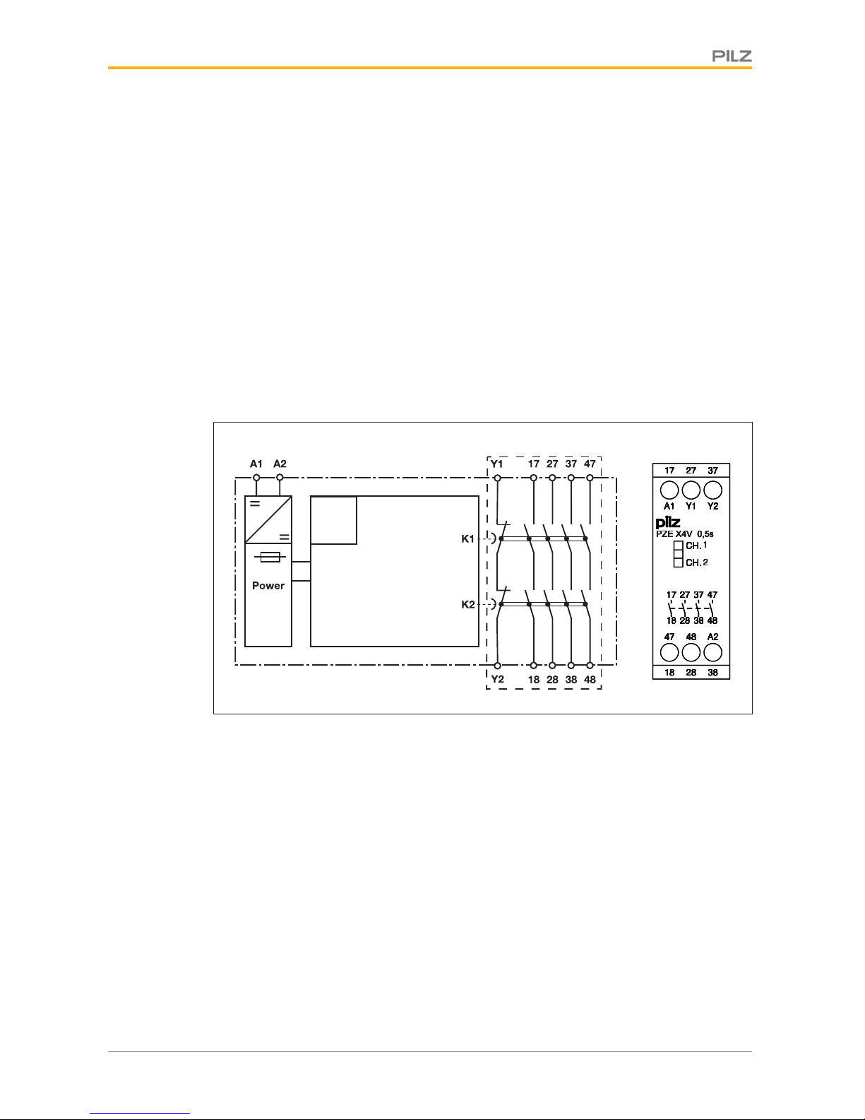
Unit features
}Positive-guided relay outputs:
– 4 safety contacts (N/O), delay-on de-energisation
}LED display for:
– Switch status of the safety contacts
}Connection for feedback loop
}Operation: single-channel
}Unit types with various delay times

PZE X4V
Operating Manual PZE X4V
1003200-EN-09 7
}See order reference for unit types
Safety features
The unit meets the following safety requirements:
}The contact expander module expands an existing circuit. As the output relays are
monitored via the base unit's feedback loop, the safety functions on the existing circuit
are transferred to the contact expander module.
}The safety function remains effective in the case of a component failure.
}Earth fault in the feedback loop:
Detected, depending on the base unit that is used.
}Earth fault in the input circuit:
The output relays de-energise and the safety contacts open.
Block diagram/terminal configuration
*
Input
CH.
CH.
A2
47 48
382818
Y2
A1
Y1
3717 27
48
3818 28
3717 27 47
CH
CHCHCHCHCHCH
.
......
CH
CHCHCHCHCHCH
.
......
A2
A2A2A2A2A2A2
47474747474747
48484848484848
38
383838383838
28
282828282828
18
181818181818
Y2
Y2Y2Y2Y2Y2Y2
A1
A1A1A1A1A1A1
Y1Y1Y1Y1Y1Y1Y1
37
373737373737
17
171717171717
27272727272727
48
484848484848
38
383838383838
18
181818181818
28
282828282828
37373737373737
17
171717171717
27
272727272727
47474747474747
PZE X4V 0,5s
PZE X4V 0,5sPZE X4V 0,5sPZE X4V 0,5sPZE X4V 0,5sPZE X4V 0,5sPZE X4V 0,5s
1
111111
2
222222
*Insulation between the non-marked area and the relay contacts: Basic insulation (over-
voltage category III), Protective separation (overvoltage category II)
Function description
The contact expansion module is an add-on device with delay-on de-energisation, and it is
used to expand a safety circuit. The contact expansion module is driven by a base unit (e.
g. emergency stop relay).
}Functional procedure once the input circuit is closed (e.g. safety contacts on the base
unit are closed):
– The supply voltage is present at input (A1) of the contact expansion module.
– The safety contacts 17-18, 27-28, 37-38 and 47-48 close.
– The LEDs "CH.1" and "CH.2" illuminate.

PZE X4V
Operating Manual PZE X4V
1003200-EN-09 8
}Functional procedure once the input circuit is opened (e.g. safety contacts on the base
unit are opened):
– The supply voltage is not present at input (A1) of the contact expansion module.
– The LEDs "CH.1" and "CH.2" go out.
– Safety contacts 17-18, 27-28, 37-38 and 47-48 are opened redundantly once the
delay time has elapsed.
NOTICE
At the latest the safety contacts open after the delay time tv + 50% of the
value, even in the case of a component failure.
Installation
}The unit should be installed in a control cabinet with a protection type of at least IP54.
}Use the notch on the rear of the unit to attach it to a DIN rail.
}Ensure the unit is mounted securely on a vertical DIN rail (35 mm) by using a fixing ele-
ment (e.g. retaining bracket or an end angle).
}If more than 2 units are installed next to each other in the control cabinet, leave a dis-
tance of at least 6 mm between the units.
Wiring
Please note:
}Information given in the "Technical details [ 10]" must be followed.
}Outputs 17-18, 27-28, 37-38 and 47-48 are delay-on de-energisation safety contacts.
}To prevent contact welding, a fuse should be connected before the output contacts (see
Technical details [ 10]).
}Calculation of the max. cable runs lmax in the input circuit:
Rlmax
Rl / km
Imax =
Rlmax = max. overall cable resistance (see Technical details [ 10])
Rl/km = cable resistance/km
}Use copper wire that can withstand 60/75°C.
}Sufficient fuse protection must be provided on all output contacts with capacitive and in-
ductive loads.
}Do not switch low currents using contacts that have been used previously with high cur-
rents.
}Ensure the EMC requirements of IEC 60204-1 are met.
}The power supply must comply with the regulations for extra low voltages with protect-
ive electrical separation (SELV, PELV) in accordance with VDE 0100, Part 410.

PZE X4V
Operating Manual PZE X4V
1003200-EN-09 9
Preparing for operation
Supply voltage AC DC
A1
A2 PZE
24 V DC
0 V
Input circuit Single-channel Dual-channel
Base unit:
Safety relay PNOZX
Driven via safety contacts
A1
A2 PZE
24 V DC
0 V
Base unit:
Safety relay PNOZmulti
Driven via semiconductor outputs
(24 VDC)
A1
PZE
A20 V
O1
L-
Feedback loop Base unit: Safety relay PNOZX Base unit: Safety relay PNOZmulti
Y1, Y2 and Input are inputs on
the base unit; they evaluate the
feedback loop
Operation
NOTICE
The safety function should be checked after initial commissioning and each
time the plant/machine is changed. The safety functions may only be
checked by qualified personnel.
Status indicators
LEDs indicate the status and errors during operation:
LED on
CH.1
Safety contacts of channel 1 are closed.
CH.2
Safety contacts of channel 2 are closed.

PZE X4V
Operating Manual PZE X4V
1003200-EN-09 10
Faults – Interference
By closing or interrupting the input circuit you can check whether the unit switches on or off
correctly.
For safety reasons, the unit cannot be started if the following faults are present:
}Contact malfunction: As the contact block is connected to a base unit,
reactivation will not be possible if the contacts have welded after the input circuit has
opened.
}Open circuit, short circuit or earth fault ( e.g. in the input circuit)
}In the case of an error, the delay-on de-energisation safety contacts may open before
the delay time has elapsed.
Dimensions in mm
Technical details
Order no. 774580 – 774582
See below for more order numbers
General 774580 774581 774582
Approvals
CCC, CE, EAC (Euras-
ian), TÜV, cULus Listed
CCC, CE, EAC (Euras-
ian), TÜV, cULus Listed
CCC, CE, EAC (Euras-
ian), TÜV, cULus Listed
Electrical data 774580 774581 774582
Supply voltage
Voltage 24 V 24 V 24 V
Kind DC DC DC
Voltage tolerance -15 %/+10 % -15 %/+10 % -15 %/+10 %
Output of external
power supply (DC) 2,5 W 2,5 W 2,5 W
Residual ripple DC 20 % 20 % 20 %
Duty cycle 100 % 100 % 100 %

PZE X4V
Operating Manual PZE X4V
1003200-EN-09 11
Electrical data 774580 774581 774582
Max. inrush current im-
pulse
Current pulse, A1 1,7 A 1,7 A 1,7 A
Pulse duration, A1 50 ms 100 ms 140 ms
Inputs 774580 774581 774582
Number 111
Voltage at
Input circuit DC 24 V 24 V 24 V
Current at
Input circuit DC 95 mA 95 mA 95 mA
Max. overall cable resist-
ance Rlmax
Single-channel at UB
DC 30 Ohm 30 Ohm 30 Ohm
Relay outputs 774580 774581 774582
Number of output con-
tacts
Safety contacts (N/O),
delayed 444
Max. short circuit current
IK 1 kA 1 kA 1 kA
Utilisation category
In accordance with the
standard EN 60947-4-1 EN 60947-4-1 EN 60947-4-1
Utilisation category of
safety contacts delayed
AC1 at 240 V 240 V 240 V
Min. current 0,01 A 0,01 A 0,01 A
Max. current 6 A 6 A 6 A
Max. power 1500 VA 1500 VA 1500 VA
DC1 at 24 V 24 V 24 V
Min. current 0,01 A 0,01 A 0,01 A
Max. current 6 A 6 A 6 A
Max. power 150 W 150 W 150 W
Utilisation category
In accordance with the
standard EN 60947-5-1 EN 60947-5-1 EN 60947-5-1
Utilisation category of
safety contacts delayed
AC15 at 230 V 230 V 230 V
Max. current 3 A 3 A 3 A
DC13 (6 cycles/min) at 24 V 24 V 24 V
Max. current 4 A 4 A 4 A

PZE X4V
Operating Manual PZE X4V
1003200-EN-09 12
Relay outputs 774580 774581 774582
Utilisation category in ac-
cordance with UL
Voltage 250 V AC G.U. (same po-
larity)
250 V AC G.U. (same po-
larity)
250 V AC G.U. (same po-
larity)
With current 6 A 6 A 6 A
Voltage 24 V DC G. U. 24 V DC G. U. 24 V DC G. U.
With current 6 A 6 A 6 A
Pilot Duty B300, R300 B300, R300 B300, R300
External contact fuse pro-
tection, safety contacts
In accordance with the
standard EN 60947-5-1 EN 60947-5-1 EN 60947-5-1
External contact fuse pro-
tection, delayed safety
contacts
Max. melting integral 66 A²s 66 A²s 66 A²s
Blow-out fuse, quick 6 A 6 A 6 A
Blow-out fuse, slow 4 A 4 A 4 A
Blow-out fuse, gG 6 A 6 A 6 A
Circuit breaker 24 V
AC/DC, characteristic
B/C 4 A 4 A 4 A
Contact material AgCuNi + 0,2 µm Au AgCuNi + 0,2 µm Au AgCuNi + 0,2 µm Au
Conventional thermal
current while loading
several contacts
774580 774581 774582
Ith per contact at UB DC
AC1:240V,DC1:24V
Conv. therm. current
with 1 contact 6 A 6 A 6 A
Conv. therm. current
with 2 contacts 5 A 5 A 5 A
Conv. therm. current
with 3 contacts 4,5 A 4,5 A 4,5 A
Conv. therm. current
with 4 contacts 4 A 4 A 4 A
Times 774580 774581 774582
Switch-on delay
With automatic start
after power on typ. 55 ms 55 ms 55 ms
With automatic start
after power on max. 200 ms 200 ms 200 ms
Delay time tv 0,5 s 1 s 2 s
Time accuracy -50 %/+50 % -50 %/+50 % -50 %/+50 %
Supply interruption before
de-energisation 250 ms 500 ms 1.000 ms
Environmental data 774580 774581 774582
Climatic suitability EN 60068-2-78 EN 60068-2-78 EN 60068-2-78

PZE X4V
Operating Manual PZE X4V
1003200-EN-09 13
Environmental data 774580 774581 774582
Ambient temperature
Temperature range -10 - 55 °C -10 - 55 °C -10 - 55 °C
Storage temperature
Temperature range -40 - 85 °C -40 - 85 °C -40 - 85 °C
Climatic suitability
Humidity 93 % r. h. at 40 °C 93 % r. h. at 40 °C 93 % r. h. at 40 °C
Condensation during op-
eration Not permitted Not permitted Not permitted
EMC EN 60947-5-1, EN
61000-6-2, EN 61326-3-1
EN 60947-5-1, EN
61000-6-2, EN 61326-3-1
EN 60947-5-1, EN
61000-6-2, EN 61326-3-1
Vibration
In accordance with the
standard EN 60068-2-6 EN 60068-2-6 EN 60068-2-6
Frequency 10 - 55 Hz 10 - 55 Hz 10 - 55 Hz
Amplitude 0,35 mm 0,35 mm 0,35 mm
Airgap creepage
In accordance with the
standard EN 60947-1 EN 60947-1 EN 60947-1
Overvoltage category III / II III / II III / II
Pollution degree 222
Rated insulation voltage 250 V 250 V 250 V
Rated impulse withstand
voltage 4 kV 4 kV 4 kV
Protection type
Mounting area (e.g.
control cabinet) IP54 IP54 IP54
Housing IP40 IP40 IP40
Terminals IP20 IP20 IP20
Mechanical data 774580 774581 774582
Mounting position Any Any Any
Mechanical life 10,000,000 cycles 10,000,000 cycles 10,000,000 cycles
Material
Bottom PPO UL 94 V0 PPO UL 94 V0 PPO UL 94 V0
Front ABS UL 94 V0 ABS UL 94 V0 ABS UL 94 V0
Top PPO UL 94 V0 PPO UL 94 V0 PPO UL 94 V0
Connection type Screw terminal Screw terminal Screw terminal
Mounting type Fixed Fixed Fixed

PZE X4V
Operating Manual PZE X4V
1003200-EN-09 14
Mechanical data 774580 774581 774582
Conductor cross section
with screw terminals
1 core flexible 0,2 - 4 mm², 24 - 10 AWG 0,2 - 4 mm², 24 - 10 AWG 0,2 - 4 mm², 24 - 10 AWG
2 core with the same
cross section, flexible
with crimp connectors,
no plastic sleeve
0,2 - 2,5 mm², 24 - 14
AWG
0,2 - 2,5 mm², 24 - 14
AWG
0,2 - 2,5 mm², 24 - 14
AWG
2 core with the same
cross section, flexible
without crimp connect-
ors or with TWIN crimp
connectors
0,2 - 2,5 mm², 24 - 14
AWG
0,2 - 2,5 mm², 24 - 14
AWG
0,2 - 2,5 mm², 24 - 14
AWG
Torque setting with screw
terminals 0,6 Nm 0,6 Nm 0,6 Nm
Dimensions
Height 87 mm 87 mm 87 mm
Width 22,5 mm 22,5 mm 22,5 mm
Depth 121 mm 121 mm 121 mm
Weight 185 g 190 g 205 g
Where standards are undated, the 2014-07 latest editions shall apply.
Order no. 774586, 774583
General 774586 774583
Approvals
CCC, CE, EAC (Eurasian), TÜV,
cULus Listed
CCC, CE, EAC (Eurasian), TÜV,
cULus Listed
Electrical data 774586 774583
Supply voltage
Voltage 24 V 24 V
Kind DC DC
Voltage tolerance -15 %/+10 % -15 %/+10 %
Output of external power supply
(DC) 2,5 W 2,5 W
Residual ripple DC 20 % 20 %
Duty cycle 100 % 100 %
Max. inrush current impulse
Current pulse, A1 1,7 A 1,7 A
Pulse duration, A1 50 ms 180 ms
Inputs 774586 774583
Number 1 1
Voltage at
Input circuit DC 24 V 24 V
Current at
Input circuit DC 95 mA 95 mA

PZE X4V
Operating Manual PZE X4V
1003200-EN-09 15
Inputs 774586 774583
Max. overall cable resistance Rl-
max
Single-channel at UB DC 30 Ohm 30 Ohm
Relay outputs 774586 774583
Number of output contacts
Safety contacts (N/O), delayed 4 4
Max. short circuit current IK 1 kA 1 kA
Utilisation category
In accordance with the standard EN 60947-4-1 EN 60947-4-1
Utilisation category of safety con-
tacts delayed
AC1 at 240 V 240 V
Min. current 0,01 A 0,01 A
Max. current 6 A 6 A
Max. power 1500 VA 1500 VA
DC1 at 24 V 24 V
Min. current 0,01 A 0,01 A
Max. current 6 A 6 A
Max. power 150 W 150 W
Utilisation category
In accordance with the standard EN 60947-5-1 EN 60947-5-1
Utilisation category of safety con-
tacts delayed
AC15 at 230 V 230 V
Max. current 3 A 3 A
DC13 (6 cycles/min) at 24 V 24 V
Max. current 4 A 4 A
Utilisation category in accordance
with UL
Voltage 250 V AC G.U. (same polarity) 250 V AC G.U. (same polarity)
With current 6 A 6 A
Voltage 24 V DC G. U. 24 V DC G. U.
With current 6 A 6 A
Pilot Duty B300, R300 B300, R300
External contact fuse protection,
safety contacts
In accordance with the standard EN 60947-5-1 EN 60947-5-1
External contact fuse protection,
delayed safety contacts
Max. melting integral 66 A²s 66 A²s
Blow-out fuse, quick 6 A 6 A
Blow-out fuse, slow 4 A 4 A
Blow-out fuse, gG 6 A 6 A
Circuit breaker 24 V AC/DC,
characteristic B/C 4 A 4 A
Contact material AgCuNi + 0,2 µm Au AgCuNi + 0,2 µm Au

PZE X4V
Operating Manual PZE X4V
1003200-EN-09 16
Conventional thermal current
while loading several contacts
774586 774583
Ith per contact at UB DC
AC1:240V,DC1:24V
Conv. therm. current with 1 con-
tact 6 A 6 A
Conv. therm. current with 2 con-
tacts 5 A 5 A
Conv. therm. current with 3 con-
tacts 4,5 A 4,5 A
Conv. therm. current with 4 con-
tacts 4 A 4 A
Times 774586 774583
Switch-on delay
With automatic start after power
on typ. 55 ms 55 ms
With automatic start after power
on max. 200 ms 200 ms
Delay time tv 0,75 s 3 s
Time accuracy -50 %/+50 % -50 %/+50 %
Supply interruption before de-ener-
gisation 375 ms 1.500 ms
Environmental data 774586 774583
Climatic suitability EN 60068-2-78 EN 60068-2-78
Ambient temperature
Temperature range -10 - 55 °C -10 - 55 °C
Storage temperature
Temperature range -40 - 85 °C -40 - 85 °C
Climatic suitability
Humidity 93 % r. h. at 40 °C 93 % r. h. at 40 °C
Condensation during operation Not permitted Not permitted
EMC EN 60947-5-1, EN 61000-6-2, EN
61326-3-1
EN 60947-5-1, EN 61000-6-2, EN
61326-3-1
Vibration
In accordance with the standard EN 60068-2-6 EN 60068-2-6
Frequency 10 - 55 Hz 10 - 55 Hz
Amplitude 0,35 mm 0,35 mm
Airgap creepage
In accordance with the standard EN 60947-1 EN 60947-1
Overvoltage category III / II III / II
Pollution degree 2 2
Rated insulation voltage 250 V 250 V
Rated impulse withstand voltage 4 kV 4 kV
Protection type
Mounting area (e.g. control cab-
inet) IP54 IP54
Housing IP40 IP40
Terminals IP20 IP20

PZE X4V
Operating Manual PZE X4V
1003200-EN-09 17
Mechanical data 774586 774583
Mounting position Any Any
Mechanical life 10,000,000 cycles 10,000,000 cycles
Material
Bottom PPO UL 94 V0 PPO UL 94 V0
Front ABS UL 94 V0 ABS UL 94 V0
Top PPO UL 94 V0 PPO UL 94 V0
Connection type Screw terminal Screw terminal
Mounting type Fixed Fixed
Conductor cross section with screw
terminals
1 core flexible 0,2 - 4 mm², 24 - 10 AWG 0,2 - 4 mm², 24 - 10 AWG
2 core with the same cross sec-
tion, flexible with crimp connect-
ors, no plastic sleeve 0,2 - 2,5 mm², 24 - 14 AWG 0,2 - 2,5 mm², 24 - 14 AWG
2 core with the same cross sec-
tion, flexible without crimp con-
nectors or with TWIN crimp con-
nectors 0,2 - 2,5 mm², 24 - 14 AWG 0,2 - 2,5 mm², 24 - 14 AWG
Torque setting with screw terminals 0,6 Nm 0,6 Nm
Dimensions
Height 87 mm 87 mm
Width 22,5 mm 22,5 mm
Depth 121 mm 121 mm
Weight 185 g 210 g
Where standards are undated, the 2014-07 latest editions shall apply.
Safety characteristic data
NOTICE
You must comply with the safety-related characteristic data in order to
achieve the required safety level for your plant/machine.
Operating
mode
EN ISO
13849-1:
2008
PL
EN ISO
13849-1:
2008
Category
EN 62061
SIL CL
EN 62061
PFHD [1/h]
IEC 61511
SIL
IEC 61511
PFD
EN ISO
13849-1:
2008
TM [year]
–PL d Cat. 3 SIL CL 2 2,48E-09 SIL 2 1,47E-05 20
All the units used within a safety function must be considered when calculating the safety
characteristic data.

PZE X4V
Operating Manual PZE X4V
1003200-EN-09 18
INFORMATION
A safety function's SIL/PL values are not identical to the SIL/PL values of
the units that are used and may be different. We recommend that you use
the PAScal software tool to calculate the safety function's SIL/PL values.
Supplementary data
CAUTION!
It is essential to consider the relay's service life graphs. The relay outputs'
safety-related characteristic data is only valid if the values in the service life
graphs are met.
The PFH value depends on the switching frequency and the load on the relay output.
If the service life graphs are not accessible, the stated PFH value can be used irrespective
of the switching frequency and the load, as the PFH value already considers the relay's
B10d value as well as the failure rates of the other components.
Service life graph
The service life graphs indicate the number of cycles from which failures due to wear must
be expected. The wear is mainly caused by the electrical load; the mechanical load is negli-
gible.
Cycles x 1000
Switching current (A)
Fig.: Service life graphs at 24 VDC and 230 VAC

PZE X4V
Operating Manual PZE X4V
1003200-EN-09 19
Number of cycles x 1000
Switching current (A)
Fig.: Service life graphs at 110 VDC
Example
}Inductive load: 0.2 A
}Utilisation category: AC15
}Contact service life: 1 000 000 cycles
Provided the application to be implemented requires fewer than 1 000 000 cycles, the PFH
value (see Technical details [ 10]) can be used in the calculation.
To increase the service life, sufficient spark suppression must be provided on all relay con-
tacts. With capacitive loads, any power surges that occur must be noted. With DC contact-
ors, use flywheel diodes for spark suppression.
Order reference
Type Features Connection type Order no.
PZE X4V 24 V DC; tV = 0.5 s Screw terminals 774580
PZE X4V 24 V DC; tV = 0.7 s Screw terminals 774586
PZE X4V 24 V DC; tV = 1 s Screw terminals 774581
PZE X4V 24 V DC; tV = 2 s Screw terminals 774582
PZE X4V 24 V DC; tV = 3 s Screw terminals 774583

PZE X4V
Operating Manual PZE X4V
1003200-EN-09 20
EC declaration of conformity
This product/these products meet the requirements of the directive 2006/42/EC for ma-
chinery of the European Parliament and of the Council. The complete EC Declaration of
Conformity is available on the Internet at www.pilz.com/support/downloads.
Representative: Norbert Fröhlich, Pilz GmbH & Co. KG, Felix-Wankel-Str. 2, 73760 Ost-
fildern, Germany
Other manuals for PZE X4V
1
Table of contents
Popular Other manuals by other brands

PORT DESIGNS
PORT DESIGNS PORT SAFE SMALL datasheet

ReelCraft
ReelCraft SD10000 Series operating instructions

Ansee
Ansee BWR-01A Operation instructions

Roger Technology
Roger Technology Agilik AG/001/PE Instruction and warnings for the installer

ElectrIQ
ElectrIQ EDD8L user manual

Paradyne
Paradyne 9261 installation instructions

OLIMEX
OLIMEX MOD-RFID125 user manual

Magnetic Autocontrol
Magnetic Autocontrol MPH 112 operating instructions

BOERBOEL
BOERBOEL Heavy Duty 8" Double Strap Hinge installation instructions

Sharper Image
Sharper Image 205979 user guide

Nidec-Shimpo
Nidec-Shimpo RK-5T manual

AC Tool Supply
AC Tool Supply SC600 user guide